CN217570912U - Bidirectional output power tool turret and processing machine with same - Google Patents
Bidirectional output power tool turret and processing machine with same Download PDFInfo
- Publication number
- CN217570912U CN217570912U CN202220610856.0U CN202220610856U CN217570912U CN 217570912 U CN217570912 U CN 217570912U CN 202220610856 U CN202220610856 U CN 202220610856U CN 217570912 U CN217570912 U CN 217570912U
- Authority
- CN
- China
- Prior art keywords
- axis
- cutter
- output
- shaft
- seat
- Prior art date
- Legal status (The legal status is an assumption and is not a legal conclusion. Google has not performed a legal analysis and makes no representation as to the accuracy of the status listed.)
- Active
Links
- 230000002457 bidirectional effect Effects 0.000 title claims abstract description 56
- 238000000034 method Methods 0.000 claims abstract description 11
- 230000005540 biological transmission Effects 0.000 claims description 40
- 238000009434 installation Methods 0.000 claims description 12
- 238000004804 winding Methods 0.000 claims description 3
- 230000008878 coupling Effects 0.000 description 7
- 238000010168 coupling process Methods 0.000 description 7
- 238000005859 coupling reaction Methods 0.000 description 7
- 230000008901 benefit Effects 0.000 description 4
- 238000003754 machining Methods 0.000 description 4
- 238000005516 engineering process Methods 0.000 description 2
- 238000010586 diagram Methods 0.000 description 1
- 230000009977 dual effect Effects 0.000 description 1
- 230000000694 effects Effects 0.000 description 1
- 238000012986 modification Methods 0.000 description 1
- 230000004048 modification Effects 0.000 description 1
- 230000000149 penetrating effect Effects 0.000 description 1
- 238000000926 separation method Methods 0.000 description 1
Images


Classifications
-
- B—PERFORMING OPERATIONS; TRANSPORTING
- B23—MACHINE TOOLS; METAL-WORKING NOT OTHERWISE PROVIDED FOR
- B23B—TURNING; BORING
- B23B29/00—Holders for non-rotary cutting tools; Boring bars or boring heads; Accessories for tool holders
- B23B29/24—Tool holders for a plurality of cutting tools, e.g. turrets
- B23B29/32—Turrets adjustable by power drive, i.e. turret heads
-
- B—PERFORMING OPERATIONS; TRANSPORTING
- B23—MACHINE TOOLS; METAL-WORKING NOT OTHERWISE PROVIDED FOR
- B23Q—DETAILS, COMPONENTS, OR ACCESSORIES FOR MACHINE TOOLS, e.g. ARRANGEMENTS FOR COPYING OR CONTROLLING; MACHINE TOOLS IN GENERAL CHARACTERISED BY THE CONSTRUCTION OF PARTICULAR DETAILS OR COMPONENTS; COMBINATIONS OR ASSOCIATIONS OF METAL-WORKING MACHINES, NOT DIRECTED TO A PARTICULAR RESULT
- B23Q3/00—Devices holding, supporting, or positioning work or tools, of a kind normally removable from the machine
- B23Q3/155—Arrangements for automatic insertion or removal of tools, e.g. combined with manual handling
- B23Q3/157—Arrangements for automatic insertion or removal of tools, e.g. combined with manual handling of rotary tools
-
- B—PERFORMING OPERATIONS; TRANSPORTING
- B23—MACHINE TOOLS; METAL-WORKING NOT OTHERWISE PROVIDED FOR
- B23Q—DETAILS, COMPONENTS, OR ACCESSORIES FOR MACHINE TOOLS, e.g. ARRANGEMENTS FOR COPYING OR CONTROLLING; MACHINE TOOLS IN GENERAL CHARACTERISED BY THE CONSTRUCTION OF PARTICULAR DETAILS OR COMPONENTS; COMBINATIONS OR ASSOCIATIONS OF METAL-WORKING MACHINES, NOT DIRECTED TO A PARTICULAR RESULT
- B23Q39/00—Metal-working machines incorporating a plurality of sub-assemblies, each capable of performing a metal-working operation
- B23Q2039/004—Machines with tool turrets
Abstract
The processing machine with the bidirectional output power tool tower is suitable for arranging at least one tool. The processing machine with the bidirectional output power tool turret comprises two clamping modules and the bidirectional output power tool turret. The bidirectional output power tool turret comprises a cutter head unit and a main shaft unit. The cutter head unit is provided with a cutter head seat. The spindle unit has a power shaft. The power shaft has two clamping portions. When the cutter head seat drives the at least one cutter to rotate to correspond to one of the clamping parts, the power shaft can drive the at least one cutter to rotate. When one clamping module is used for replacing a workpiece, the bidirectional output power tool turret can simultaneously process the workpiece clamped by the other clamping module. Therefore, the idle time can be reduced, and the overall processing efficiency is improved. And removing the clamping module from the processing machine with the bidirectional output power tool turret to obtain the bidirectional output power tool turret.
Description
Technical Field
The utility model relates to a processing machine equipment especially relates to a two-way output power sword tower and utensil two-way output power sword tower's processing machine.
Background
An existing machining apparatus includes a machine body, a movable chuck for holding a workpiece, a turret mounted on the machine body, a plurality of tools mounted on the turret, and a transmission unit disposed on the turret and capable of driving one of the tools to rotate to machine the workpiece.
When the existing processing machine needs to replace the cutter, the corresponding cutter rotates to the position corresponding to the transmission unit by rotating the tool turret, and then the transmission unit can drive the corresponding cutter to rotate, so that the aims of automatic cutter changing and processing can be fulfilled.
However, when the machining operation is completed and the movable chuck is replacing the workpiece, the transmission unit is in an idle state, and the movable chuck needs to be started again after clamping the next object to be machined, so that the maximum machining benefit of the conventional machining machine cannot be achieved.
Disclosure of Invention
An object of the utility model is to provide a can promote two-way output power sword tower of processing benefit.
Another objective of the present invention is to provide a processing machine with a bidirectional power tool turret, which can improve the processing efficiency.
Therefore, the utility model discloses two-way output power tool turret is applicable to and supplies at least one cutter setting. The bidirectional output power tool turret comprises a base unit, a driving unit, a cutter head unit and a main shaft unit.
The driving unit is arranged on the base unit and comprises a driving motor and an output shaft which can be driven by the driving motor to rotate around an extension axis. The cutter unit comprises a cutter seat arranged on the base unit. The cutterhead seat is adapted for disposal of the at least one cutter and is operable to rotate about the axis of extension. The main shaft unit comprises a linkage shaft capable of rotating around the extension axis synchronously with the output shaft, a first transmission piece formed on the linkage shaft, a power shaft extending along the output axis intersected with the extension axis, and a second transmission piece formed on the power shaft and connected with the first transmission piece. The power shaft has two clamping portions oppositely disposed along the output axis. Each clamp is capable of driving the at least one tool to rotate about the output axis. When the cutter head seat rotates around the extension axis and drives the at least one cutter to rotate to one of the corresponding clamping parts, the linkage shaft rotates around the extension axis to drive the first transmission piece and the second transmission piece, so that the power shaft drives the at least one cutter to rotate around the output axis.
Bidirectional output power tool turret, be applicable to and supply the several cutter setting, the cutter head seat has and winds extend the axis interval and set up and be applicable to the confession respectively the several installation department that the cutter set up, the cutter head seat winds extend the axis and rotate when making one of them installation department correspond one of them clamping part, wherein another installation department is corresponding to another clamping part.
Bidirectional output power sword tower, the first driving medium of main shaft unit for set firmly in a bevel gear outside the interlock axle, the second driving medium for set firmly in a bevel gear outside the power shaft.
Bidirectional output power tool turret, blade disc unit still including set up in base unit's tool changing motor, set up in base unit can be by tool changing motor drive and wind extend axis pivoted rotate seat, rigid coupling in rotate the first clutch of seat, and the rigid coupling in the blade disc seat can be operated and with the second clutch that first clutch is connected or is separated.
The utility model discloses utensil two-way output power tool turret's processing machine is applicable to and supplies at least one cutter setting and processes a plurality of work piece. The processing machine with the bidirectional output power tool tower comprises a machine body module, two clamping modules, a moving module and the bidirectional output power tool tower.
The clamping modules are arranged on the machine body module and are arranged oppositely along the output axis at intervals. Each clamping module is adapted to clamp one of the workpieces. The moving module is arranged on the machine body module and comprises a moving seat capable of moving between the clamping modules along the extension direction of the output axis. The bidirectional output power tool turret comprises a base unit, a driving unit, a cutter head unit and a main shaft unit.
The base unit is arranged on the moving module and can be driven by the moving module to move between the clamping modules along the extension direction of the output axis. The drive unit is disposed on the base unit and has a drive motor and an output shaft that is driven by the drive motor to rotate about an extension axis intersecting the output axis. The cutter unit is provided with a cutter seat arranged on the base unit. The cutter head seat is adapted for the at least one cutter to be disposed and operable for rotation about the extension axis. The main shaft unit is provided with a linkage shaft capable of rotating around the extension axis synchronously with the output shaft, a first transmission piece formed on the linkage shaft, a power shaft extending along the output axis, and a second transmission piece formed on the power shaft and connected with the first transmission piece. The power shaft has two clamping portions oppositely disposed along the output axis. Each clamping portion can drive the at least one tool to rotate around the output axis.
When the cutter head seat rotates around the extension axis and drives the at least one cutter to rotate to one of the corresponding clamping parts, the linkage shaft rotates around the extension axis and can drive the first transmission piece and the second transmission piece, so that the power shaft drives the at least one cutter to rotate around the output axis.
Utensil two-way output power tool turret's processing machine, the removal module still including can for remove the seat and follow the guide holder that the extending direction of extension axis removed, the base unit of two-way output power tool turret set up in the guide holder.
Utensil two-way output power tool turret's processing machine, remove the module still including set up in organism module and ability drive remove the seat and follow the extending direction of output axis removes and produces the first driving piece of location, and set up in remove the seat and can drive the guide holder is followed the extending direction of extending axis removes and produces the second driving piece of location.
Utensil two-way output power tool turret's processing machine, two-way output power tool turret's main shaft unit's first driving medium for set firmly in a bevel gear outside the interlock axle, the second driving medium for set firmly in a bevel gear outside the power axle.
Utensil two-way output power tool turret's processing machine, be applicable to and supply the several cutter setting, the blade disc seat of two-way output power tool turret has the winding extend the axis interval and set up and be applicable to the confession respectively the several installation department that the cutter set up, the blade disc seat winds when extending the axis and rotating to make one of them installation department correspond one of them clamping part, wherein another installation department is corresponding to another clamping part.
Utensil two-way output power tool turret's processing machine, two-way output power tool turret's blade disc unit still have set up in base unit's tool changing motor, set up in base unit and can by tool changing motor drive and wind extend axis pivoted rotate seat, rigid coupling in rotate the first clutch of seat, and the rigid coupling in the blade disc seat can be operated and with the second clutch of first clutch connection or separation.
The utility model has the advantages that: because the power shaft is provided with the clamping parts which are oppositely arranged along the output axis, when the bidirectional output power tool turret is arranged between the clamping modules and one of the clamping modules is used for replacing the workpiece, the bidirectional output power tool turret can simultaneously process the workpiece clamped by the other clamping module, thereby reducing the idle time and improving the overall processing efficiency.
Drawings
FIG. 1 is a perspective view of a processing machine with a bidirectional power output turret according to an embodiment of the present invention;
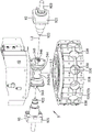
FIG. 2 is a partial exploded perspective view of the embodiment;
fig. 3 is a perspective combination view of a driving unit, a cutter head unit and a spindle unit of the double-output power turret of the embodiment, and a plurality of cutters;
FIG. 4 is a fragmentary exploded perspective view of the dual direction power take-off turret and two of the cutters therein;
FIG. 5 is a cross-sectional view taken along line V-V of FIG. 3;
FIG. 6 is a cross-sectional view taken along line VI-VI of FIG. 3;
fig. 7 is a top view schematic diagram illustrating a clamping module of the bi-directional power take-off turret approaching the right side.
Detailed Description
The present invention will be described in detail with reference to the accompanying drawings and examples.
Before the present invention is described in detail, it should be noted that like components are represented by like numerals throughout the following description.
Referring to fig. 1 to 4, the first embodiment of the processing machine with bidirectional power output turret of the present invention is suitable for setting a plurality of tools 92 and processing a plurality of workpieces 91 (see fig. 7).
Each tool 92 includes a body 921, and a holding section 922 and a processing section 923 extending from the body 921. The clamping section 922 is a flat block.
The processing machine with the bidirectional output power tool tower comprises a machine body module 1, two clamping modules 2, a conveying module 3, a moving module 4 and a bidirectional output power tool tower 5. The two-way output power tool tower 5 is defined to extend along an extension axis L1.
The machine body module 1 has a first seat 11 and two second seats 12 extending from the first seat 11 in the same direction and spaced from each other along an output axis L2 perpendicular to the extending axis L1.
The clamping modules 2 are respectively disposed on the second seat 12 of the machine body module 1. The clamping modules 2 are arranged opposite one another at a distance along the output axis L2. Each clamping module 2 is adapted to clamp one of the workpieces 91.
The conveying module 3 is disposed at an end of the second seat 12 of the machine body module 1 opposite to the first seat 11, and is adapted to convey the workpieces 91 to the clamping module 2 one by one, and to take away the workpieces 91 from the clamping module 2 after the workpieces 91 are processed.
The moving module 4 is disposed on the first seat 11 of the machine body module 1, and includes a moving seat 41 capable of moving between the clamping modules 2 along the extending direction of the output axis L2, a guiding seat 42 capable of moving along the extending direction of the output axis L1 relative to the moving seat 41, a first driving member 43 disposed on the first seat 11 and capable of driving the moving seat 41 to move along the extending direction of the output axis L2 and generate positioning, and a second driving member 44 disposed on the moving seat 41 and capable of driving the guiding seat 42 to move along the extending direction of the output axis L1 and generate positioning. It should be noted that, in the present embodiment, the technology of using the first driving component 43 and the second driving component 44 to respectively drive the moving seat 41 and the guiding seat 42 to move and generate the positioning can be implemented by a linear motor, a servo motor, a lead screw motor or other technologies.
Referring to fig. 2 to 5, the bidirectional power output turret 5 includes a base unit 51, a driving unit 52, a cutter head unit 53, and a spindle unit 54.
The base unit 51 is disposed on the guide seat 42 of the moving module 4, and can be driven by the moving module 4 to move between the clamping modules 2 along the extending direction of the output axis L2, and also can be driven by the moving module 4 to move relative to the first seat 11 along the extending direction of the extending axis L1. The base unit 51 has a housing portion 511 and a fixing portion 512 penetrating the housing portion 511.
The driving unit 52 is disposed on the base unit 51, and has a driving motor 521 and an output shaft 522 that is driven by the driving motor 521 to rotate around the extending axis L1 and disposed in the fixing portion 512.
In this embodiment, the first clutch 534 and the second clutch 535 are fluted discs that can engage with and disengage from each other, and when the first clutch 534 is operated to move downward along the extension axis L1 toward the second clutch 535, the first clutch 534 engages with the second clutch 535, so that the cutter changing motor 531 can drive the rotating base 532 and the cutter base 533 to rotate, and when the first clutch 534 is operated to move upward along the extension axis L1 away from the second clutch 535, the first clutch 534 disengages from the second clutch 535, so that the cutter changing motor 531 drives the rotating base 532 to rotate, and the cutter base 533 is not driven to rotate.
The cutter head holder 533 is adapted to be arranged and operable to rotate about the extension axis L1 for the cutter 92. The cutter head holder 533 has a plurality of mounting portions 538 spaced around the extension axis L1 and adapted to be respectively disposed for the cutters 92. The mounting portion 538 circumferentially defines an interior space 530. Each mounting portion 538 has a through hole 539 for the respective cutter 92 to be disposed and communicating between the inner space 530 and the outside.
Referring to fig. 3, 4 and 6, the spindle unit 54 includes a linking shaft 541 capable of rotating around the extending axis L1 synchronously with the output shaft 522, a first transmission member 542 formed on the linking shaft 541, a power shaft 543 extending along the output axis L2 and extending into the inner space 530, and a second transmission member 544 formed on the power shaft 543 and connected to the first transmission member 542. In this embodiment, the first transmission member 542 is a bevel gear fixedly disposed outside the coupling shaft 541, and the second transmission member 544 is a bevel gear fixedly disposed outside the power shaft 543 and engaged with the first transmission member 542.
The power shaft 543 has two clamping portions 545 provided oppositely along the output axis L2. Each clamp 545 is capable of driving the respective knife 92 in rotation about the output axis L2. Each clamp 545 is formed with a recess 546 in which the clamping section 922 of the respective tool 92 is located. Each of the grooves 546 is open at opposite ends about the extension axis L1, so that the clamping section 922 of the cutter 92 can enter and exit the groove 546 when the cutter holder 533 is rotated about the extension axis L1.
When the cutter head holder 533 is rotated about the extension axis L1 to make one of the mounting portions 538 correspond to one of the clamping portions 545 and the clamping section 922 of the corresponding cutter 92 is located in the groove 546 of the one of the clamping portions 545, the other mounting portion 538 also corresponds to the other clamping portion 545 and the clamping section 922 of the cutter 92 arranged on the other mounting portion 538 is also located in the groove 546 of the other clamping portion 545.
When the cutter head seat 533 rotates around the extension axis L1 and drives the two cutters 92 to rotate to the positions respectively corresponding to the clamping portions 545, the linking shaft 541 rotates around the extension axis L1 to drive the first transmission member 542 and the second transmission member 544, so that the power shaft 543 drives the cutters 92 to rotate around the output axis L2.
The operation of the processing machine with bidirectional power output turret will be described below with reference to fig. 7, wherein the relative positions of the components are shown in fig. 2, 5 and 6, and the left and right directions are described in the perspective of fig. 7. In order to clearly understand the operation and advantages of the processing machine with a bidirectional output power turret, the following description will first describe the operation process of the processing machine with a bidirectional output power turret as a whole, and the detailed operation and principle of the bidirectional output power turret 5 will be described in the following paragraphs.
When the processing machine with the bidirectional output power tool turret is used, firstly, after the conveying module 3 conveys one workpiece 91 to the right-hand clamping module 2, the first driving member 43 of the moving module 4 moves the moving seat 41 and the bidirectional output power tool turret 5 to a position relatively close to the right-hand clamping module 2 along the extending direction of the output axis L2, and then the bidirectional output power tool turret 5 can perform processing operation on the workpiece 91 clamped by the right-hand clamping module 2, and at this time, the conveying module 3 can convey the other workpiece 91 to the left-hand clamping module 2 at the same time.
After the bidirectional output power turret 5 finishes processing the workpiece 91 clamped by the right clamping module 2, the first driving element 43 of the moving module 4 can move the moving seat 41 and the bidirectional output power turret 5 to a position relatively approaching the left clamping module 2 along the extending direction of the output axis L2 (fig. 7 only reveals that the bidirectional output power turret 5 is located at a position relatively approaching the right clamping module 2, and does not reveal that the bidirectional output power turret 5 is located at a position relatively approaching the left clamping module 2), and process the workpiece 91 clamped by the left clamping module 2, and at this time, the conveying module 3 can simultaneously take off the workpiece 91 which is finished and clamped by the right clamping module 2, and then convey another workpiece 91 to the right clamping module 2.
By repeating the above-described operations, the bidirectional power take-off turret 5 can repeatedly machine the workpiece 91 held by the left and right holding modules 2.
Next, the detailed operation manner and principle of the two-way output power turret 5 in the above operation steps will be described.
First, the first clutch 534 is operated to approach downward along the extension axis L1 and engage the second clutch 535, so that the tool changer motor 531 can drive the rotary base 532 and the cutter base 533 to rotate. Next, the tool 92 to be used is rotated to the clamping portion 545 of the power shaft 543 corresponding to the side of the workpiece 91 to be machined, and then the first clutch 534 is disengaged from the second clutch 535. Then, the driving motor 521 drives the output shaft 522 and the linking shaft 541 to rotate around the extension axis L1, and the tool 92 held by the power shaft 543 and the power shaft 543 can be rotated around the output axis L2 by the transmission between the first transmission member 542 and the second transmission member 544, so that the workpiece 91 to be machined can be machined.
As described above, since the power shaft 543 has the clamping portions 545 oppositely disposed along the output axis L2, and the clamping portions 545 can clamp the corresponding tools 92, respectively, to process the workpiece 91 clamped by the clamping modules 2, when the bidirectional output power turret 5 is disposed between the clamping modules 2, and when one of the clamping modules 2 is replacing the workpiece 91, the bidirectional output power turret 5 can process the workpiece 91 clamped by the other clamping module 2 at the same time, so that idle time can be reduced and overall processing efficiency can be improved.
By arranging the moving module 4, the bidirectional power output turret can be driven to move along the extending direction of the output axis L2, so that the distance between the clamping modules 2 can be set to be wider, when the bidirectional power output turret needs to process a workpiece 91 clamped by the clamping module 2 on one side, the moving module 4 moves the bidirectional power output turret to approach the clamping module 2 on one side and to be far away from the clamping module 2 on the other side, and the influence of a tool 92 on the non-processing side on the conveying module 3 to convey the next workpiece 91 can be avoided.
In addition, referring to fig. 2 to 5, an embodiment of the bidirectional output power turret 5 of the present invention is to exclude the machine body module 1, the clamping module 2, the conveying module 3, and the moving module 4 from the processing machine with the bidirectional output power turret, and the shapes and the combination space shapes of the other components and the expected achievable effects are the same as those of the processing machine with the bidirectional output power turret, and are not repeated.
To sum up, because the power shaft 543 of the two-way output power turret 5 has an edge the output axis L2 is oppositely arranged the clamping portion 545, so when the two-way output power turret 5 is arranged between the clamping modules 2, when one of the clamping modules 2 is being replaced the workpiece 91, the two-way output power turret 5 can process the workpiece 91 clamped by the other clamping module 2 at the same time, so that the idle time can be reduced and the overall processing efficiency can be improved, and the purpose of the utility model can be achieved.
The above description is only an embodiment of the present invention, and the scope of the present invention should not be limited thereby, and all the simple equivalent changes and modifications made according to the claims and the contents of the specification should be included in the scope of the present invention.
Claims (10)
1. A bidirectional output power tool turret is suitable for arranging at least one tool; the method is characterized in that: the bidirectional output power tool turret comprises:
a base unit;
the driving unit is arranged on the base unit and comprises a driving motor and an output shaft which can be driven by the driving motor to rotate around an extension axis;
the cutter head unit comprises a cutter head seat arranged on the base unit, and the cutter head seat is suitable for being arranged by the at least one cutter and can be operated to rotate around the extension axis; and
the main shaft unit comprises a linkage shaft capable of rotating around the extension axis synchronously with the output shaft, a first transmission piece formed on the linkage shaft, a power shaft extending along the output axis intersected with the extension axis, and a second transmission piece formed on the power shaft and connected with the first transmission piece, wherein the power shaft is provided with two clamping parts arranged oppositely along the output axis, each clamping part can drive the at least one cutter to rotate around the output axis,
when the cutter head seat rotates around the extension axis and drives the at least one cutter to rotate to one of the corresponding clamping parts, the linkage shaft rotates around the extension axis to drive the first transmission piece and the second transmission piece, so that the power shaft drives the at least one cutter to rotate around the output axis.
2. The bi-directional output power turret of claim 1, wherein: be applicable to and supply several cutter setting, the cutter head seat has the winding extend the axis interval and set up and be applicable to the confession respectively the several installation department that the cutter set up, the cutter head seat winds extend the axis and rotate when making one of them installation department correspond one of them clamping part, wherein another installation department is corresponding to another clamping part.
3. The bi-directional power take off turret of claim 1, wherein: the first transmission piece of the main shaft unit is a bevel gear fixedly arranged outside the linkage shaft, and the second transmission piece is a bevel gear fixedly arranged outside the power shaft.
4. The bi-directional power take off turret of claim 1, wherein: the cutter head unit further comprises a cutter changing motor arranged on the base unit, a rotating seat arranged on the base unit and driven by the cutter changing motor to rotate around the extension axis, a first clutch fixedly connected to the rotating seat, and a second clutch fixedly connected to the cutter head seat and capable of being operated to be connected with or separated from the first clutch.
5. A processing machine with a bidirectional output power tool turret is suitable for being provided with at least one tool and processing a plurality of workpieces; the method is characterized in that: the processing machine with the bidirectional output power tool turret comprises:
a body module;
the two clamping modules are arranged on the machine body module and are oppositely arranged at intervals along the output axis, and each clamping module is suitable for clamping one workpiece;
the moving module is arranged on the machine body module and comprises a moving seat capable of moving between the clamping modules along the extension direction of the output axis; and
the bidirectional output power tool turret comprises
A base unit arranged on the moving module and driven by the moving module to move between the clamping modules along the extending direction of the output axis,
a drive unit provided to the base unit and having a drive motor and an output shaft driven by the drive motor to rotate about an extension axis intersecting the output axis,
a cutter head unit having a cutter head seat provided in said base unit, said cutter head seat being adapted for providing said at least one cutter to be disposed and operable to rotate about said extension axis, an
The main shaft unit is provided with a linkage shaft which can synchronously rotate around the extending axis with the output shaft, a first transmission piece formed on the linkage shaft, a power shaft extending along the output axis, and a second transmission piece formed on the power shaft and connected with the first transmission piece, the power shaft is provided with two clamping parts which are oppositely arranged along the output axis, each clamping part can drive the at least one cutter to rotate around the output axis,
when the cutter head seat rotates around the extension axis and drives the at least one cutter to rotate to one of the corresponding clamping parts, the linkage shaft rotates around the extension axis to drive the first transmission piece and the second transmission piece, so that the power shaft drives the at least one cutter to rotate around the output axis.
6. The processing machine with bidirectional power output of claim 5, wherein: the moving module further comprises a guide seat capable of moving relative to the moving seat along the extending direction of the extending axis, and the base unit of the bidirectional output power turret is arranged on the guide seat.
7. The converting machine with bi-directional output power of claim 6, wherein: the moving module further comprises a first driving piece and a second driving piece, the first driving piece is arranged on the machine body module and can drive the moving seat to move along the extending direction of the output axis and generate positioning, and the second driving piece is arranged on the moving seat and can drive the guide seat to move along the extending direction of the extending axis and generate positioning.
8. The processing machine with bidirectional power output of claim 5, wherein: the first transmission piece of the main shaft unit of the bidirectional output power tool tower is a bevel gear fixedly arranged outside the linkage shaft, and the second transmission piece is a bevel gear fixedly arranged outside the power shaft.
9. The processing machine with bidirectional power output turret as set forth in claim 5, wherein: be applicable to and supply the setting of several cutter, the blade disc seat of two-way output power sword tower has the winding extend the axis interval and set up and be applicable to the confession respectively the several installation department that the cutter set up, the blade disc seat winds extend the axis and rotate when making one of them installation department correspond one of them clamping part, and wherein another installation department is corresponding to another clamping part.
10. The processing machine with bidirectional power output turret as set forth in claim 5, wherein: the cutter head unit of the bidirectional output power cutter tower is also provided with a cutter changing motor arranged on the base unit, a rotating seat arranged on the base unit and driven by the cutter changing motor to rotate around the extension axis, a first clutch fixedly connected with the rotating seat, and a second clutch fixedly connected with the cutter head seat and operated to be connected with or separated from the first clutch.
Applications Claiming Priority (2)
| Application Number | Priority Date | Filing Date | Title |
|---|---|---|---|
| TW110112569 | 2021-04-07 | ||
| TW110112569A TWI765644B (en) | 2021-04-07 | 2021-04-07 | Bidirectional output power turret and processing machine with bidirectional output power turret |
Publications (1)
| Publication Number | Publication Date |
|---|---|
| CN217570912U true CN217570912U (en) | 2022-10-14 |
Family
ID=82594356
Family Applications (2)
| Application Number | Title | Priority Date | Filing Date |
|---|---|---|---|
| CN202210274895.2A Pending CN115194198A (en) | 2021-04-07 | 2022-03-21 | Bidirectional output power tool turret and processing machine with same |
| CN202220610856.0U Active CN217570912U (en) | 2021-04-07 | 2022-03-21 | Bidirectional output power tool turret and processing machine with same |
Family Applications Before (1)
| Application Number | Title | Priority Date | Filing Date |
|---|---|---|---|
| CN202210274895.2A Pending CN115194198A (en) | 2021-04-07 | 2022-03-21 | Bidirectional output power tool turret and processing machine with same |
Country Status (2)
| Country | Link |
|---|---|
| CN (2) | CN115194198A (en) |
| TW (1) | TWI765644B (en) |
Family Cites Families (9)
| Publication number | Priority date | Publication date | Assignee | Title |
|---|---|---|---|---|
| JP3044456B2 (en) * | 1995-11-27 | 2000-05-22 | 本田技研工業株式会社 | Turret type machine tool |
| WO1999011408A1 (en) * | 1997-08-29 | 1999-03-11 | Citizen Watch Co., Ltd. | Automatic lathe and method of controlling same |
| ES2616762T3 (en) * | 2011-05-31 | 2017-06-14 | Gildemeister Italiana S.P.A. | Machine tool |
| CN102615298B (en) * | 2012-03-29 | 2014-01-29 | 沈阳机床(集团)设计研究院有限公司 | Single servo power cutter holder based on basic motion time (BMT) cutter disk |
| TWM466741U (en) * | 2013-03-05 | 2013-12-01 | Youji Machine Ind Co Ltd | Machine too with rotational tool turret |
| CN203817882U (en) * | 2014-05-12 | 2014-09-10 | 厦门力浩机械科技有限公司 | Machine tool cutter disc driving mechanism |
| CN205904698U (en) * | 2016-07-07 | 2017-01-25 | 宝鸡忠诚机床股份有限公司 | A power knife rest for driving and change power cutter |
| CN106625030B (en) * | 2017-01-03 | 2019-12-10 | 杭州大天数控机床有限公司 | composite flexible manufacturing unit |
| JP7026462B2 (en) * | 2017-08-28 | 2022-02-28 | シチズン時計株式会社 | Turret tool post |
-
2021
- 2021-04-07 TW TW110112569A patent/TWI765644B/en active
-
2022
- 2022-03-21 CN CN202210274895.2A patent/CN115194198A/en active Pending
- 2022-03-21 CN CN202220610856.0U patent/CN217570912U/en active Active
Also Published As
| Publication number | Publication date |
|---|---|
| TW202239503A (en) | 2022-10-16 |
| TWI765644B (en) | 2022-05-21 |
| CN115194198A (en) | 2022-10-18 |
Similar Documents
| Publication | Publication Date | Title |
|---|---|---|
| EP0349641B1 (en) | Machine tool | |
| CN210451762U (en) | Turning and milling combined machine tool | |
| CN113894549A (en) | High-precision numerical control machine tool machining all-in-one machine | |
| CN217570912U (en) | Bidirectional output power tool turret and processing machine with same | |
| CN217095710U (en) | Programmable tailstock numerical control lathe | |
| CN217096749U (en) | Double-spindle numerical control lathe capable of realizing multi-process machining | |
| CN207387041U (en) | Multicutter saves process lathe | |
| CN211708737U (en) | Numerical control tapping, drilling and milling integrated machine | |
| CN210475535U (en) | Numerical control machining machine tool for bearing | |
| CN210172979U (en) | Quick-opening and slow-opening valve core integrated special machine tool | |
| CN210790007U (en) | Turn-milling combined machining center workbench structure | |
| CN110814762A (en) | High-efficiency numerical control turning and milling compound machine | |
| CN208614213U (en) | A kind of linear guide special production line machining tool | |
| CN211162831U (en) | High-efficiency numerical control turning and milling compound machine | |
| CN214769033U (en) | Compound digit control machine tool of two main shaft formula four-axis linkage | |
| CN220128095U (en) | Turning and milling integrated machine | |
| CN220825704U (en) | Automatic tool changing right-angle spindle | |
| CN211361337U (en) | Large carriage dovetail device for numerical control lathe | |
| CN212578000U (en) | Drilling, tapping and key slot milling integrated special machine for processing perforating gun | |
| CN101564769B (en) | Heavy cutting numerically controlled lathe | |
| CN217254487U (en) | Composite machining cutter table behind one's back | |
| CN220480847U (en) | Double-spindle turning and milling composite lathe for synchronously machining front and back surfaces | |
| CN220659345U (en) | Numerical control combined machine tool for milling | |
| CN210938397U (en) | Multi-station and multi-shaft machining center | |
| CN220462916U (en) | Multifunctional turning and milling compound machine tool |
Legal Events
| Date | Code | Title | Description |
|---|---|---|---|
| GR01 | Patent grant | ||
| GR01 | Patent grant |