CN217550864U - Washing machine backplate sheet metal component stamping die of convenient ejection of compact - Google Patents
Washing machine backplate sheet metal component stamping die of convenient ejection of compact Download PDFInfo
- Publication number
- CN217550864U CN217550864U CN202220509471.5U CN202220509471U CN217550864U CN 217550864 U CN217550864 U CN 217550864U CN 202220509471 U CN202220509471 U CN 202220509471U CN 217550864 U CN217550864 U CN 217550864U
- Authority
- CN
- China
- Prior art keywords
- fixedly connected
- washing machine
- sheet metal
- stamping die
- metal component
- Prior art date
- Legal status (The legal status is an assumption and is not a legal conclusion. Google has not performed a legal analysis and makes no representation as to the accuracy of the status listed.)
- Active
Links
Images

Landscapes
- Press Drives And Press Lines (AREA)
Abstract
The utility model provides a make things convenient for washing machine backplate sheet metal component stamping die of ejection of compact relates to washing machine backplate sheet metal component production technical field. The automatic cleaning device comprises a workbench, fixedly connected with supporting plates are arranged on two sides of the top of the workbench, a transverse plate and a transverse plate are fixedly connected to the top of the supporting plate, a first sliding groove is formed in one side of the supporting plate, a lower die table is fixedly connected to the top of the workbench, and a cleaning assembly is arranged on the front side of the lower die table. This make things convenient for washing machine backplate sheet metal component stamping die of ejection of compact starts driving motor, drive gear revolve, rotation through the gear, it removes to clear up the defective material to drive the clearance pole, the defective material can fall into inside the collecting box, drive the inside incomplete material of collecting box roll-off discharge gate to clear up through the pulling handle, when having solved artifical clearance, the trouble operation still has the problem of potential safety hazard, the centralized processing's that the defective material was collected effect has also been reached simultaneously, the work efficiency of punching press has been improved.
Description
Technical Field
The utility model relates to a stamping die specifically is washing machine backplate sheet metal component stamping die of the convenient ejection of compact belongs to washing machine backplate sheet metal component production technical field.
Background
The washing machine backplate sheet metal component is the important part in the washing machine manufacturing, and current washing machine backplate sheet metal component uses press and stamping die to exert external force to panel and section bar etc. to make it produce plastic deformation or separation to obtain the washing machine backplate sheet metal component of required shape and size, so need use stamping die to carry out stamping forming to required washing machine backplate sheet metal component.
Traditional washing machine backplate sheet metal component stamping die, in the use, place sheet metal component raw and other materials in the bed die mesa and carry out stamping forming to it through last stamping die more, but the produced punching press waste material of this kind of punching press mode needs artifical manual clear away, and the clearance is got up too troublesome, has very big potential safety hazard in the clearance process to the waste material that produces can scatter and be difficult to collect on the punching press mesa, has reduced the work efficiency of punching press.
SUMMERY OF THE UTILITY MODEL
Technical problem to be solved
The utility model aims at providing the washing machine backplate sheet metal component stamping die who makes things convenient for the ejection of compact just for solving above-mentioned problem to solve produced punching press waste material among the prior art, need artifical manual clear away, the clearance gets up too troublesome, has very big potential safety hazard among the clearance process, and the waste material that produces can scatter and be difficult to collect on the punching press mesa, has reduced the work efficiency's of punching press problem.
(II) technical scheme
In order to achieve the above purpose, the utility model discloses a following technical scheme realizes: make things convenient for washing machine backplate sheet metal component stamping die of ejection of compact includes the workstation, workstation top both sides fixedly connected with backup pad, two backup pad top fixedly connected with diaphragm, two first spout has all been seted up to backup pad one side, workstation top fixedly connected with lower die platform, lower die platform front side is equipped with the clearance subassembly.
Preferably, the clearance subassembly includes driving motor, driving motor fixed connection is in the workstation top, driving motor output fixedly connected with gear, driving motor's model can choose for use for its main purpose of Z9DK90-24 to drive the motion of clearance subassembly, through the setting of gear to after driving motor starts, drive the clearance subassembly and clear up the defective material, convenient and fast more.
Preferably, the lower die table front side fixedly connected with horizontal pole, the second spout has been seted up to horizontal pole inside, the inside sliding connection of second spout has the slider, slider top fixedly connected with clearance pole through the setting of clearance pole to when the slider removes, drive its removal on the lower die table and reach the purpose of wasing the defective material.
Preferably, slider front side fixedly connected with rack, the rack is connected with the gear engagement, slider one side fixedly connected with spring, spring one end fixed connection is in the inside one side of second spout, through the setting of rack to when gear revolve, drive the slider and slide in the inside of second spout under the effect of rack.
Preferably, the equal fixedly connected with baffle box in lower moulding bed both sides, two the drain hole has all been seted up to the baffle box bottom, the drain hole runs through in the workstation top, through the setting of baffle box to in the back of the defective material clearance to lower moulding bed, collect the defective material fast.
Preferably, a discharge port is formed in the rear side of the workbench, a third chute is formed in the bottom of the interior of the discharge port, a collecting box is connected to the interior of the third chute in a sliding mode, a handle is fixedly connected to the front side of the collecting box, and the collecting box can be conveniently drawn out after enough residual materials are collected through the arrangement of the third chute, so that the residual materials can be conveniently cleaned.
Preferably, diaphragm bottom two pneumatic cylinders of fixedly connected with, two pneumatic cylinder bottom fixedly connected with slide, the slide both sides are sliding connection respectively inside first spout, slide bottom fixedly connected with goes up the mould platform, through the setting of slide to in fixing last mould platform, thereby make things convenient for the punching press to go on more stably.
The utility model provides a make things convenient for washing machine backplate sheet metal component stamping die of ejection of compact, its beneficial effect who possesses as follows:
1. this make things convenient for washing machine backplate sheet metal component stamping die of ejection of compact starts driving motor, drive gear revolve, rotation through the gear, it removes to drive the slider, it removes to drive the clearance pole, clear up the defective material, setting through the drain hole, the defective material can fall into inside the collecting box, drive inside the collecting box roll-off discharge gate and clear up the defective material through the pulling handle, when having solved artifical clearance, the troublesome poeration still has the problem of potential safety hazard, the centralized processing's that the defective material was collected effect has also been reached simultaneously, the work efficiency of punching press has been improved.
2. This make things convenient for washing machine backplate sheet metal component stamping die workstation rear side of ejection of compact opens and is equipped with the discharge gate, and the third spout has been seted up to the inside bottom of discharge gate, and the inside sliding connection of third spout has the collecting box, and collecting box front side fixedly connected with handle through the setting of third spout to after collecting sufficient defective material, make the collecting box more conveniently take out, the convenience is cleared up the defective material.
Drawings
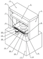
Fig. 1 is a schematic view of the overall structure of the present invention;
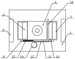
FIG. 2 is a schematic view of a partial structure of the present invention;
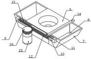
FIG. 3 is a schematic top view of the present invention;
fig. 4 is the schematic view of the cleaning assembly structure of the present invention.
In the figure: 1. a work table; 2. a support plate; 3. a transverse plate; 4. a first chute; 5. a slide plate; 6. a lower die table; 7. a material guide chute; 8. a material leakage port; 9. a cross bar; 10. a second chute; 11. a slider; 12. a rack; 13. a spring; 14. cleaning the rod; 15. a drive motor; 16. a gear; 17. a hydraulic cylinder; 18. feeding a die table; 19. a discharge port; 20. a third chute; 21. a collection box; 22. a handle.
Detailed Description
The embodiment of the utility model provides a make things convenient for washing machine backplate sheet metal component stamping die of ejection of compact.
Referring to fig. 1, 2, 3 and 4, the stamping device comprises a workbench 1, wherein two sides of the top of the workbench 1 are fixedly connected with supporting plates 2, the tops of the two supporting plates 2 are fixedly connected with a transverse plate 3, the bottom of the transverse plate 3 is fixedly connected with two hydraulic cylinders 17, the bottoms of the two hydraulic cylinders 17 are fixedly connected with a sliding plate 5, two sides of the sliding plate 5 are respectively connected with the inner parts of first sliding grooves 4 in a sliding manner, the bottom of the sliding plate 5 is fixedly connected with an upper die table 18, the upper die table 18 is fixed through the arrangement of the sliding plate 5, so that stamping is more stable, one side of each of the two supporting plates 2 is provided with the first sliding groove 4, the top of the workbench 1 is fixedly connected with a lower die table 6, two sides of the lower die table 6 are respectively and fixedly connected with guide grooves 7, the bottoms of the two guide grooves 7 are respectively provided with a material leakage opening 8, the material leakage opening 8 penetrates through the top of the workbench 1, through the arrangement of the guide grooves 7, so that after the residual materials on the lower die table 6 are cleaned, the residual materials are rapidly collected, a cross rod 9 is fixedly connected to the front side of the lower die table 6, a second chute 10 is formed in the cross rod 9, a sliding block 11 is slidably connected to the inside of the second chute 10, a rack 12 is fixedly connected to the front side of the sliding block 11, the rack 12 is meshed with a gear 16, a spring 13 is fixedly connected to one side of the sliding block 11, one end of the spring 13 is fixedly connected to one side of the inside of the second chute 10, through the arrangement of the rack 12, so that when the gear 16 rotates, the sliding block 11 is driven to slide in the second chute 10 under the action of the rack 12, the cleaning assembly comprises a driving motor 15, the driving motor 15 is fixedly connected to the top of the workbench 1, the output end of the driving motor 15 is fixedly connected with the gear 16, through the arrangement of the gear 16, so that after the driving motor 15 is started, the cleaning assembly is driven to clean the residual materials, more convenient and fast, 6 front sides of lower mould platform are equipped with the clearance subassembly, and the clearance subassembly includes driving motor 15, 15 fixed connection of driving motor in 1 tops of workstation, 15 output fixedly connected with gears 16 of driving motor, setting through gears 16 to in 15 start-up backs of driving motor, drive the clearance subassembly and clear up the defective material, convenient and fast more.
Specifically, after the raw material is punched, the driving motor 15 is started to drive the output shaft of the driving motor to rotate, the gear 16 fixed at the output end of the driving motor is driven to rotate, the rack 12 connected with the driving motor in a meshed mode is driven to move through the rotation of the gear 16, the sliding block 11 is driven to move in the second sliding groove 10 and is fixedly connected with the cleaning rod 14 through the sliding block 11, the cleaning rod 14 can be driven to move at the top of the lower die table 6 when the sliding block 11 moves, the residual materials remained at the top of the lower die table 6 can be pushed and cleaned, the residual materials can be pushed to the inside of the guide groove 7 through the pushing of the cleaning rod 14, the residual materials can fall into the collecting box 21 arranged in the discharging port 19 through the arrangement of the leakage port 8 arranged at the bottom of the guide groove 7, after enough residual materials are collected in the collecting box 21, the collecting box 21 can be driven to slide in the third sliding groove 20 through the pulling of the handle 22, the residual materials in the collecting box 21 can be cleaned until the residual materials slide out of the discharging port 19, the residual materials can be cleaned manually, the problem that the operation hidden danger of the safety problem of the punching operation and the trouble of the collection of the punching operation is solved, and the problem that the trouble of the concentrated processing of the punching operation is also improved.
Referring to fig. 1, fig. 2, fig. 3 and fig. 4 again, a discharge hole 19 is formed in the rear side of the workbench 1, a third chute 20 is formed in the bottom inside the discharge hole 19, a collection box 21 is connected inside the third chute 20 in a sliding manner, a handle 22 is fixedly connected to the front side of the collection box 21, and through the arrangement of the third chute 20, after enough residual materials are collected, the collection box 21 is more conveniently drawn out, and the residual materials are conveniently cleaned.
Referring to fig. 1, fig. 2, fig. 3 and fig. 4 again, a cross bar 9 is fixedly connected to the front side of the lower mold table 6, a second chute 10 is formed in the cross bar 9, a sliding block 11 is slidably connected to the inside of the second chute 10, a cleaning rod 14 is fixedly connected to the top of the sliding block 11, and the cleaning rod 14 is arranged so as to drive the sliding block 11 to move on the lower mold table 6 to clean the residual materials when the sliding block 11 moves.
The working principle is as follows: start driving motor 15, drive gear 16 and rotate, rotation through gear 16, it removes to drive slider 11, it removes to drive clearance pole 14, clear up the defective material, setting through drain hole 8, the defective material can fall into inside collecting box 21, drive inside collecting box 21 roll-off discharge gate 19 and clear up the defective material through pulling handle 22, when having solved artifical clearance, the trouble of operation still has the problem of potential safety hazard, the centralized processing's that collects the defective material effect has also been reached simultaneously, the work efficiency of punching press has been improved.
The foregoing shows and describes the basic principles and principal features of the invention, together with the advantages thereof. It will be understood by those skilled in the art that the present invention is not limited to the above embodiments, and that the foregoing embodiments and descriptions are provided only to illustrate the principles of the present invention without departing from the spirit and scope of the present invention. The scope of the invention is defined by the appended claims and equivalents thereof.
Claims (7)
1. Make things convenient for washing machine backplate sheet metal component stamping die of ejection of compact, including workstation (1), its characterized in that: workstation (1) top both sides fixedly connected with backup pad (2), two backup pad (2) top fixedly connected with diaphragm (3), two first spout (4) have all been seted up to backup pad (2) one side, workstation (1) top fixedly connected with bed die platform (6), bed die platform (6) front side is equipped with the clearance subassembly.
2. The washing machine backplate sheet metal part stamping die convenient for discharging according to claim 1, characterized in that: the cleaning assembly comprises a driving motor (15), the driving motor (15) is fixedly connected to the top of the workbench (1), and a gear (16) is fixedly connected to the output end of the driving motor (15).
3. The washing machine backplate sheet metal part stamping die convenient for discharging according to claim 1, characterized in that: the lower die table is characterized in that a cross rod (9) is fixedly connected to the front side of the lower die table (6), a second sliding groove (10) is formed in the cross rod (9), a sliding block (11) is connected to the inside of the second sliding groove (10) in a sliding mode, and a cleaning rod (14) is fixedly connected to the top of the sliding block (11).
4. The washing machine backplate sheet metal part stamping die convenient for discharging according to claim 3, characterized in that: slider (11) front side fixedly connected with rack (12), rack (12) are connected with gear (16) meshing, slider (11) one side fixedly connected with spring (13), spring (13) one end fixed connection is in the inside one side of second spout (10).
5. The washing machine backplate sheet metal part stamping die convenient for discharging according to claim 1, characterized in that: the material discharging device is characterized in that material guide grooves (7) are fixedly connected to two sides of the lower die table (6), material discharging openings (8) are formed in the bottoms of the material guide grooves (7), and the material discharging openings (8) penetrate through the top of the workbench (1).
6. The washing machine rear baffle sheet metal part stamping die convenient to discharge according to claim 1, characterized in that: a discharge hole (19) is formed in the rear side of the workbench (1), a third sliding groove (20) is formed in the bottom of the interior of the discharge hole (19), a collecting box (21) is connected to the interior of the third sliding groove (20) in a sliding mode, and a handle (22) is fixedly connected to the front side of the collecting box (21).
7. The washing machine rear baffle sheet metal part stamping die convenient to discharge according to claim 1, characterized in that: diaphragm (3) bottom fixedly connected with two pneumatic cylinders (17), two pneumatic cylinder (17) bottom fixedly connected with slide (5), slide (5) both sides are sliding connection inside first spout (4) respectively, slide (5) bottom fixedly connected with cope match-plate pattern platform (18).
Priority Applications (1)
| Application Number | Priority Date | Filing Date | Title |
|---|---|---|---|
| CN202220509471.5U CN217550864U (en) | 2022-03-10 | 2022-03-10 | Washing machine backplate sheet metal component stamping die of convenient ejection of compact |
Applications Claiming Priority (1)
| Application Number | Priority Date | Filing Date | Title |
|---|---|---|---|
| CN202220509471.5U CN217550864U (en) | 2022-03-10 | 2022-03-10 | Washing machine backplate sheet metal component stamping die of convenient ejection of compact |
Publications (1)
| Publication Number | Publication Date |
|---|---|
| CN217550864U true CN217550864U (en) | 2022-10-11 |
Family
ID=83468367
Family Applications (1)
| Application Number | Title | Priority Date | Filing Date |
|---|---|---|---|
| CN202220509471.5U Active CN217550864U (en) | 2022-03-10 | 2022-03-10 | Washing machine backplate sheet metal component stamping die of convenient ejection of compact |
Country Status (1)
| Country | Link |
|---|---|
| CN (1) | CN217550864U (en) |
-
2022
- 2022-03-10 CN CN202220509471.5U patent/CN217550864U/en active Active
Similar Documents
| Publication | Publication Date | Title |
|---|---|---|
| CN110814074B (en) | Mould convenient to shaping unloading | |
| CN216540376U (en) | Continuous stamping die for forming aluminum shell | |
| CN217550864U (en) | Washing machine backplate sheet metal component stamping die of convenient ejection of compact | |
| CN215544212U (en) | Lower box cover stamping device | |
| CN113843332A (en) | Be used for floor drain stamping forming equipment | |
| CN216065059U (en) | Waste cleaning device for stamping metal plates | |
| CN212238832U (en) | Metal pipe punching machine | |
| CN219924231U (en) | Punching machine capable of automatically collecting punching residual materials | |
| CN111941693A (en) | Automatic stripping and collecting device for thin rubber plates | |
| CN112246969A (en) | Punching die | |
| CN217831472U (en) | Perforating device of mould production usefulness | |
| CN215614344U (en) | Tapered roller production is with stamping device who possesses automatic collection waste material function | |
| CN214321817U (en) | General type powder metallurgy die | |
| CN215657412U (en) | Auto-parts stamping die that possesses function of cleaning | |
| CN220372077U (en) | Waste collection device for continuous stamping | |
| CN220880384U (en) | Cold header | |
| CN218555374U (en) | Stamping die's waste recovery mechanism | |
| CN218310315U (en) | Stamping equipment with work piece garbage collection | |
| CN214391976U (en) | Waste collecting device for automobile stamping die | |
| CN216501795U (en) | Automobile parts punching press collection device | |
| CN219561658U (en) | Metal peeling machine | |
| CN220072955U (en) | Sheet metal part stamping forming die | |
| CN215279387U (en) | Sheet metal stamping die with waste recycling function | |
| CN219314104U (en) | Waste removing and winding integrated device for die cutting machine | |
| CN217343171U (en) | Stamping die capable of self-cleaning |
Legal Events
| Date | Code | Title | Description |
|---|---|---|---|
| GR01 | Patent grant | ||
| GR01 | Patent grant |