SUMMERY OF THE UTILITY MODEL
The application provides a good radiator unit and projection equipment dispel the heat in order to solve the bad problem of projection equipment heat dissipation among the prior art.
In order to solve the above problem, the present application provides a heat dissipation assembly, including:
the light path cavity is formed by the side wall which is arranged around the periphery of the bottom wall, the side wall is provided with a light through hole, and one side of the shell, which is far away from the bottom wall, is provided with a first opening;
the water cooling plate is covered on the first opening; and
and the air cooling module comprises an airflow driving device, and the airflow driving device is used for driving airflow circulation in the light path cavity.
Wherein the surface of the water-cooling plate facing the light path chamber is provided with a light trapping structure.
The light trapping structure comprises a plurality of light trapping units protruding from the surface of the water cooling plate facing the light path chamber.
The light trapping units are arranged in an array, and the light trapping units are of a tooth-shaped structure or a needle-shaped structure.
The light trapping structure comprises a plurality of light trapping units which are recessed on the surface of the water cooling plate facing the light path chamber.
The light trapping units are arranged in an array mode and are grooves.
Wherein a surface of the water-cooled plate facing the optical path chamber has a matte coating.
Wherein, the casing set up in the water-cooling board with between the forced air cooling module, the forced air cooling module set up in the diapire is kept away from one side of light path cavity, the casing the diapire has air intake and air outlet, the forced air cooling module passes through the air intake with the air outlet with the light path cavity intercommunication.
The air cooling module further comprises a bottom plate and a side plate, the side plate surrounds the periphery of the bottom plate and forms an accommodating cavity, the airflow driving device is arranged in the accommodating cavity, a second opening is formed in one side, away from the bottom plate, of the air cooling module, and the bottom wall cover of the shell is arranged at the second opening.
Wherein the air cooling module also comprises a clapboard which divides the accommodating cavity into an air inlet cavity and an air outlet cavity, the air inlet cavity corresponds to the air inlet, and the air outlet cavity corresponds to the air outlet.
Wherein, the baffle has breach portion, airflow drive arrangement card is located the breach, perhaps, the baffle has the through-hole, airflow drive arrangement wears to locate or airflow drive arrangement's air-out end corresponds to the through-hole
Wherein the airflow driving device is arranged in the optical path chamber.
Wherein, the casing has the barricade, the barricade has inlet air channel and air-out passageway, airflow drive device's air-out end wears to locate or corresponds to the air-out passageway.
The application also provides a projection device comprising the heat dissipation assembly.
The beneficial effects of the embodiment of the application are that: the application provides a radiator unit and projection equipment, radiator unit includes casing, water-cooling board and forced air cooling module, the casing has diapire and lateral wall, the lateral wall centers on the periphery of diapire sets up and forms the light path cavity, the lateral wall is provided with logical unthreaded hole, the casing is kept away from one side of diapire has first opening, water-cooling board lid is located first opening, the forced air cooling module includes airflow drive device, airflow drive device is used for the drive airflow circulation in the light path cavity, through forced air cooling module realizes airflow circulation in the casing, with the equilibrium temperature in the casing, through the water-cooling board will the heat in the casing is outside sparse has solved the bad problem of projection equipment heat dissipation among the prior art, has realized a good radiator unit and projection equipment dispels the heat.
Detailed Description
The technical solutions in the embodiments of the present application will be clearly and completely described below with reference to the drawings in the embodiments of the present application. It is to be understood that the specific embodiments described herein are merely illustrative of the application and are not limiting of the application. It should be further noted that, for the convenience of description, only some of the structures associated with the present application are shown in the drawings, not all of them. All other embodiments, which can be derived by a person skilled in the art from the embodiments given herein without making any creative effort, shall fall within the protection scope of the present application.
In the description of the present application, it is to be understood that the terms "center," "longitudinal," "lateral," "length," "width," "thickness," "upper," "lower," "front," "rear," "left," "right," "vertical," "horizontal," "top," "bottom," "inner," "outer," "clockwise," "counterclockwise," and the like are used in the orientations and positional relationships indicated in the drawings for convenience in describing the present application and for simplicity in description, and are not intended to indicate or imply that the referenced devices or elements must have a particular orientation, be constructed in a particular orientation, and be operated in a particular manner, and are not to be construed as limiting the present application. Furthermore, the terms "first", "second" and "first" are used for descriptive purposes only and are not to be construed as indicating or implying relative importance or implicitly indicating the number of technical features indicated. Thus, features defined as "first", "second", may explicitly or implicitly include one or more of the described features. In the description of the present application, "a plurality" means two or more unless specifically limited otherwise.
In the description of the present application, it should be noted that, unless otherwise explicitly stated or limited, the terms "mounted," "connected," and "connected" are to be construed broadly, and may be, for example, a fixed connection, a detachable connection, or an integral connection; may be mechanically, electrically or may be in communication with each other; either directly or indirectly through intervening media, either internally or in any other relationship. The specific meaning of the above terms in the present application can be understood by those of ordinary skill in the art as appropriate.
In this application, unless expressly stated or limited otherwise, the first feature "on" or "under" the second feature may comprise direct contact of the first and second features, or may comprise contact of the first and second features not directly but through another feature in between. Also, the first feature "on," "above" and "over" the second feature may include the first feature being directly above and obliquely above the second feature, or simply indicating that the first feature is at a higher level than the second feature. A first feature being "under," "below," and "beneath" a second feature includes the first feature being directly under and obliquely below the second feature, or simply meaning that the first feature is at a lesser elevation than the second feature.
Reference herein to "an embodiment" means that a particular feature, structure, or characteristic described in connection with the embodiment can be included in at least one embodiment of the application. The appearances of the phrase in various places in the specification are not necessarily all referring to the same embodiment, nor are separate or alternative embodiments mutually exclusive of other embodiments. It is explicitly and implicitly understood by one skilled in the art that the embodiments described herein can be combined with other embodiments.
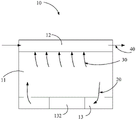
Referring to fig. 1-3, a heat dissipation assembly 10 is provided. The heat dissipation assembly 10 includes a housing 11, a water cooling plate 12 and an air cooling module 13. The housing has an optical path chamber 11a. The air cooling module 13 includes an airflow driving device 132. The airflow driving device 132 is used for driving the airflow circulation in the optical path chamber 11a.
The air 20 in the housing 11 is driven by the air cooling module 13, and the heat 30 in the housing 11 is absorbed by the water-cooling plate 12 and is dissipated outwards by the medium 40 in the water-cooling plate 12.
Referring to fig. 4-5, the housing 11 has a bottom wall 111 and a side wall 112. The bottom wall 111 is substantially rectangular. A notch portion 111a is included at a position of one of the sides of the rectangle. The notch portion 111a is used for fitting with another component. The side wall 112 is disposed around the periphery of the bottom wall 111 and forms the light path chamber 11a. The sidewall 112 has a recess 112a. The recessed portion 112a corresponds to the notch portion 111a of the bottom wall 111. The recess 112a is used to mate with other components. The side wall 112 of the housing 11 is provided with a light passing hole 112b. The side of the housing 11 away from the bottom wall 111 has a first opening 11b. The bottom wall 111 has an inlet 111b and an outlet 111c. In this embodiment, the number of the air inlets 111b is 2, and the number of the air outlets 111c is 1. In other embodiments, the number of the air inlets 111b and the number of the air outlets 111c may also be flexibly set according to actual needs. The housing 11 may be made of plastic, aluminum alloy, stainless steel, copper alloy, or the like.
Referring to fig. 6, the water-cooling plate 12 is disposed to cover the first opening 11b. The water-cooling plate 12 includes a water-cooling cavity structure 121. The water-cooling cavity structure 121 is a sealed cavity. The sealed chamber is used for water flow to circulate in the sealed chamber, so as to take away heat in the light path chamber 11a.
The water-cooled cavity structure 121 includes an upper cover 1211, a bottom cover 1212 and a connecting wall 1213. The upper cap 1211 and the lower cap 1212 close both ends of the connecting wall 1213. The bottom cover 1212 faces the optical path chamber 11a. The water-cooling cavity structure 121 may be made of a high thermal conductive metal material, such as copper or copper alloy, and may also be made of aluminum alloy, stainless steel, or the like. The water-cooling cavity 121 can rapidly absorb heat in the optical cavity 11a, and conduct the heat to the medium in the water-cooling cavity 121, where the heat is transferred from the medium to the outside. The medium can be water, ethanol and the like, and can also be other fluid cold accumulation media.
The water-cooling plate 12 is substantially rectangular, and one side of the rectangle has a notch portion 12a, and the notch portion 12a is used for matching with other components. The water-cooling plate 12 and the first opening 11b are formed in the same shape to cover the side of the housing 11 away from the bottom wall 111.
The water-cooling plate 12 further includes a water inlet 122 and a water outlet 123, and the water inlet 122 and the water outlet 123 are disposed on the connecting wall 1213.
The surface of the water-cooled plate 12 facing the light path chamber 11a has a light trapping structure 124. Specifically, the light trapping structure 124 is disposed on a surface of the bottom cover 1212 facing the light path chamber 11a.
In one embodiment, the light trapping structure 124 includes a plurality of light trapping units 1241 protruding from the surface of the water-cooled plate 12 facing the light path chamber 11a. The light trapping units 1241 are tooth-shaped structures disposed on the surface of the water-cooling plate 12 facing the optical path chamber 11a. The tooth-shaped structures are arranged in an array. In this embodiment, the tooth-shaped structure is a rectangular parallelepiped tooth-shaped structure, and the height of the tooth-shaped structure is greater than the width or length of the tooth-shaped structure. As shown in fig. 7, the tooth structure may also be a cylindrical tooth structure, and the height of the tooth structure is larger than the diameter of the tooth structure. In other embodiments, the tooth-like structure may also be a needle-like structure. It should be noted that, the shape of the tooth-like structure can be flexibly set according to actual needs.
In one embodiment, the light trapping structure 124 includes a plurality of light trapping units 1241 recessed on the surface of the water-cooled plate 12 facing the light path chamber 11a. The light trapping units 1241 are arranged in an array. The light trapping unit 1241 is a groove.
In this application, light trapping structure 124 can effectively absorb stray light in light path cavity 11a, thereby avoids casing 11 light leak, simultaneously, also will stray light's light energy conversion is heat energy, heat energy passes through water-cooling plate 12 is outside sparse. Further, the light trapping structure 124 also serves as a heat absorbing fin of the water cooling plate 12, so that heat in the heat dissipation assembly 10 can be effectively absorbed, and the heat exchange efficiency is improved.
The application provides an adoption water-cooling board 12 radiator unit 10 can effectively avoid using the semiconductor refrigeration chip, the cost that not only reduces, simultaneously, has avoided radiator unit whole bulky, the system is complicated.
The surface of the water-cooled plate 12 facing the optical path chamber 11a has a matte coating 1242. The matte coating 1242 enhances the radiation absorption of heat within the heat sink assembly 10 by the water-cooled plate 12. In some embodiments, the matte coating 1242 can be a black coating.
In this embodiment, the housing 11 is disposed between the water cooling module 12 and the air cooling module 13. The air cooling module 13 is disposed on a side of the bottom wall 111 away from the optical cavity 11a. The air-cooling module 13 is communicated with the optical path chamber 11a through the air inlet 111b and the air outlet 111c. In this embodiment, the heat in the housing 11 is dissipated outwards through the water-cooling plate 12, and then the water-cooling plate 12 and the air-cooling module 13 are disposed on two sides of the housing 11, so as to increase the distance between the water-cooling plate 12 and the air-cooling module 13, and make the temperature in the housing 11 sufficiently balanced.
Referring to fig. 8, the air-cooling module 13 includes an air-cooling cavity structure 131. The air-cooled cavity structure 131 includes a bottom plate 1311 and side plates 1312. The side plates 1312 are disposed around the periphery of the bottom plate 1311 and form a receiving chamber 13a. The side of the air cooling module 13 away from the bottom plate 1311 is provided with a second opening 13b. The bottom wall 111 of the housing 11 covers the second opening 13b.
The air-cooled cavity structure 131 further includes a partition 1313. The partition 1313 divides the accommodating chamber 13a into an air inlet chamber 13a1 and an air outlet chamber 13a2. The air inlet chamber 13a1 corresponds to the air inlet 111b. The outlet chamber 13a2 corresponds to the outlet 111c.
The airflow driving device 132 is disposed in the accommodating chamber 13a. The airflow driving device 132 is used for driving the airflow circulation in the optical path chamber 11a. The airflow driving device 132 is communicated with the air inlet chamber 13a1 and the air outlet chamber 13a2. Specifically, the airflow driving device 132 may be disposed through the partition 1313 to communicate the air inlet chamber 13a1 and the air outlet chamber 13a2. In this embodiment, the partition 1313 has a notch 1313a, and the airflow driving device 132 is clamped in the notch 1313a and passes through the partition 1313, so as to communicate the air inlet chamber 13a1 and the air outlet chamber 13a2. In other embodiments, the partition 1313 may also have a through hole, and the airflow driving device 132 is disposed through the through hole or the air outlet end of the airflow driving device 132 corresponds to the through hole, so as to communicate the air inlet chamber 13a1 and the air outlet chamber 13a2.
The air in the housing 11 enters the air inlet chamber 13a1 from the air inlet 111b, enters the air outlet chamber 13a2 after passing through the airflow driving device 132, and then flows back to the housing 11 from the air outlet chamber 13a2.
The airflow driving device 132 may be a vortex fan or an axial fan. The air flow driving device 132 blows air in the low-temperature area to the high-temperature area, so that the temperature of the light path chamber 11a is uniform, and meanwhile, the air flow driving device 132 plays a role in enhancing air disturbance of the cavity and strengthening the heat convection intensity.
The air cooling module 13 enhances the air circulation inside the heat dissipation assembly 10, not only balances the temperature inside the shell 11, but also enhances the heat convection capability of the air, so that the heat can be effectively absorbed by the water cooling plate 12, and the heat dissipation assembly 10 is more suitable for high-power projection equipment.
In the application, the temperature equalization inside the cavity is realized through forced air cooling circulation, so that the over-high temperature of a local optical device is avoided; meanwhile, forced air cooling can enhance the heat exchange efficiency of the water cooling plate 12, accelerate the conduction of heat in the heat dissipation assembly 10 to the water cooling plate 12 and reduce the temperature difference between the air in the heat dissipation assembly 10 and the water cooling plate 12; the surface of the water-cooling plate 12 facing the light path chamber 11a is provided with the extinction coating 1242, and the light trapping structure 124 in a fin shape is provided to enhance the radiation heat exchange capability and the absorption capability of stray light; the water cooling plate 12 is provided with a water channel, and the water cooling heat dissipation capacity and the cavity temperature can be accurately controlled by controlling the duty ratio of the water pump through software.
Referring to fig. 9 to 11, in another embodiment of the present application, the airflow driving device 132 may also be disposed in the optical path chamber 11a. The housing 11 has a retaining wall 113 therein. The retaining wall 113 has an air inlet passage 113a and an air outlet passage 113b. The air outlet end of the airflow driving device 132 is disposed through or corresponds to the air outlet channel 113b. In this embodiment, the airflow driving device 132 is disposed in the optical path chamber 11a, so as to meet the trend of compacting the components of the apparatus, thereby reducing the volume of the heat dissipation assembly 10 as a whole, and meanwhile, the airflow driving device 132 directly acts on the optical path chamber 11a, so as to accelerate the airflow circulation in the optical path chamber 11a, so that the temperature in the optical path chamber 11a is sufficiently balanced.
Referring to fig. 12, the present application further provides a projection apparatus 100. The projection device 100 includes the heat sink assembly 10 as previously described. The projection equipment further comprises a light source, and the light source is arranged in the light source accommodating part. The light emitted from the light source is transmitted outward through the light-passing hole 112b.
The application provides a radiator unit and projection equipment, radiator unit includes casing, water-cooling board and forced air cooling module, the casing has diapire and lateral wall, the lateral wall centers on the periphery of diapire sets up and forms the light path cavity, the lateral wall is provided with logical unthreaded hole, the casing is kept away from one side of diapire has first opening, water-cooling board lid is located first opening, the forced air cooling module includes airflow drive device, airflow drive device is used for the drive airflow circulation in the light path cavity, through forced air cooling module realizes airflow circulation in the casing, with the equilibrium temperature in the casing, through the water-cooling board will heat in the casing is outside sparse, has solved the bad problem of projection equipment heat dissipation among the prior art, has realized a radiator unit and projection equipment that the heat dissipation is good.
The above description is only an embodiment of the present application, and not intended to limit the scope of the present application, and all modifications of equivalent structures and equivalent processes performed by the content of the present specification and the attached drawings, or directly or indirectly applied to other related technical fields, are also included in the scope of the present application.