CN217543151U - Motor rotating speed acquisition device of metering automation terminal detection system - Google Patents
Motor rotating speed acquisition device of metering automation terminal detection system Download PDFInfo
- Publication number
- CN217543151U CN217543151U CN202122808540.0U CN202122808540U CN217543151U CN 217543151 U CN217543151 U CN 217543151U CN 202122808540 U CN202122808540 U CN 202122808540U CN 217543151 U CN217543151 U CN 217543151U
- Authority
- CN
- China
- Prior art keywords
- rotating speed
- module
- display
- utility
- speed acquisition
- Prior art date
- Legal status (The legal status is an assumption and is not a legal conclusion. Google has not performed a legal analysis and makes no representation as to the accuracy of the status listed.)
- Active
Links
Images




Landscapes
- Arrangements For Transmission Of Measured Signals (AREA)
Abstract
The utility model relates to a measurement automation terminal detecting system's motor speed collection system, including the treater, drive module, sensor circuit, the module that resets, clock module and the keyboard of being connected with the treater, drive module is connected with the display. The circuit design of the utility model is simple and novel, and the common single chip microcomputer and the existing module can be combined; the utility model has a large speed measuring range, and the maximum measurable rotating speed can reach 32 ten thousand revolutions per minute; the utility model discloses the procedure logic is simple, and follow-up extension and maintenance are convenient.
Description
Technical Field
The utility model belongs to the technical field of motor speed acquisition and specifically relates to a measurement automation terminal detecting system's motor speed collection system.
Background
The meter checking line fully combines an automation technology with a power system calibrating device and is used for realizing the automatic and intelligent detection of various electric energy meters and terminals.
The rotating speed is a parameter which is widely applied in engineering and is an important characteristic parameter in the performance test of energy equipment and power machinery, because many characteristic parameters of the power machinery are determined according to the functional relation between the characteristic parameters and the rotating speed, such as the exhaust volume of a compressor, the shaft power, the output power of an internal combustion engine and the like, and the vibration of the power machinery, the airflow pulsation of a pipeline, the abrasion state of various working parts and the like are closely related to the rotating speed.
The methods for measuring the rotating speed are various, the types of measuring instruments are various, and the use conditions and the measuring precision are different. The working modes according to the rotation speed measurement can be divided into two categories: a contact type rotating speed measuring instrument and a non-contact type rotating speed measuring instrument. The former must contact with the measured shaft directly when in use, such as centrifugal tachometers, magnetic tachometers, tachogenerator and the like; the latter does not need to contact with the measured rotating shaft when in use, such as a photoelectric tachometer, an electronic digital tachometer, a flash tachometer and the like. The traditional method of measuring engine speed is by using a photoelectric tachometer. When the method is used for measurement, the cursor paper is stuck on the rotating shaft of the engine, and measuring personnel are required to control the distance between the revolution meter and the cursor paper within a very close range, so that the measurement is very inconvenient.
With the rapid development of science and technology, the rotating speed measuring instrument is in the modern and electronic line. Used in the past a contact-type measuring instrument is provided, such as centrifugal tachometers, magnetic tachometers, microgenerator tachometers and clocks and watches are timing tachometers which are all subjected to cold falling in sequence; however, although the flash velocimeter which measures the speed by using the method of synchronizing the flash with the rotating speed of the measured shaft with the known frequency belongs to a non-contact instrument, the flash velocimeter still has application at present, but has fallen into a secondary position. Instead, non-contact electronic and digital speed measuring instruments are used. Most of the rotating speed meters have the advantages of small volume, light weight, accurate reading, convenient use and the like, are easy to realize computer screen display and printout, can continuously reflect the change of the rotating speed, can measure the average rotating speed of the engine under the stable condition, and can also be used for measuring the instantaneous rotating speed of the engine under the specific condition of a small enough time interval.
SUMMERY OF THE UTILITY MODEL
In order to solve the problem that circuit design among the prior art is complicated, measure inconvenient, maintain inconvenient, the utility model provides a measurement automation terminal detecting system's motor speed collection system for single, three-phase electric energy meter, measurement automation terminal (single-phase, three-phase, terminal, mutual-inductor) automatic check out system.
The technical scheme of the utility model is specifically as follows:
the utility model provides a measurement automation terminal detecting system's motor speed collection system, includes the treater, drive module, sensor circuit, reset module, clock module and the keyboard of being connected with the treater, drive module is connected with the display.
Further, the sensor adopts UGN3144 Hall sensor, converts the rotational speed of surveying into pulse signal.
Further, the processor is an ARM single chip microcomputer and adopts AT89C51.
Further, the display is an LED digital display with 4 and 7 segments of LED digital tubes for dynamic display.
Furthermore, the device also comprises a power supply which adopts double power supplies to completely isolate the relay driving power supply from the singlechip and the peripheral circuit power supply thereof.
Furthermore, the device is connected with a plurality of acquisition terminals through a repeater.
Compared with the prior art, the beneficial effects of the utility model are specifically as follows:
the circuit design of the utility model is simple and novel, and the common single chip microcomputer and the existing module can be combined;
the utility model is based on the existing program, the speed measuring range is large, the maximum measurable rotating speed reaches 32 thousands of revolutions per minute, if the rotating speed is measured more than the measured rotating speed, the existing software counting scheme can be adopted for unlimited expansion;
the utility model discloses program logic is simple, and follow-up extension and maintenance are convenient.
Drawings
Fig. 1 is a block diagram of the hardware structure of the present invention;
fig. 2 is a schematic structural diagram of the data acquisition of the acquisition terminal of the present invention;
fig. 3 is a circuit diagram of the reset module of the present invention;
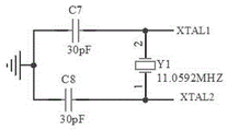
fig. 4 is a circuit diagram of an ARM clock of the present invention;
fig. 5 is a diagram of the rotational speed measurement logic architecture of the present invention;
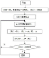
FIG. 6 is a main program flow of the rotation speed measurement of the single chip microcomputer of the present invention;
fig. 7 is a flow chart of the program for calculating the rotation speed according to the present invention;
FIG. 8 is a flowchart of a division procedure of the present invention;
fig. 9 is a flowchart of the display procedure of the present invention.
Detailed Description
The technical solutions in the embodiments will be described clearly and completely with reference to the drawings in the embodiments of the present application, and it is obvious that the described embodiments are only a part of the embodiments of the present application, and not all of the embodiments. All other embodiments, which can be derived by a person skilled in the art from the examples without making any creative effort, shall fall within the protection scope of the present application.
Unless otherwise defined, technical or scientific terms used in the embodiments of the present application should have the ordinary meaning as understood by those having ordinary skill in the art. The use of "first," "second," and similar terms in the present embodiments does not denote any order, quantity, or importance, but rather the terms are used to distinguish one element from another. The word "comprising" or "comprises", and the like, means that the element or item listed before the word covers the element or item listed after the word and its equivalents, but does not exclude other elements or items. "mounted," "connected," and "coupled" are to be construed broadly and may, for example, be fixedly coupled, detachably coupled, or integrally coupled; they may be connected directly or indirectly through intervening media, or they may be interconnected between two elements. "Upper," "lower," "left," "right," "lateral," "vertical," and the like are used solely in relation to the orientation of the components in the figures, and these directional terms are relative terms that are used for descriptive and clarity purposes and that can vary accordingly depending on the orientation in which the components in the figures are placed.
The measurement principle of this embodiment is as follows:
measuring the number m1 of pulses generated by the pulse generator during a certain measuring time T to measure the rotating speed, and assuming that the number of arcs rotated by the rotating shaft during the time T is X tau, the rotating speed n can be represented by the following formula:

the radian number X tau of the rotating shaft can be represented by m1

Substituting the formula (3-2) into the formula (3-1) to obtain:
the expression of the rotation speed n is:

p-is the number of pulses generated by the pulse generator when the rotating shaft rotates for one circle;
n-rotational speed unit: (rev/min);
t-timing time unit: (seconds).
In this method, a quantization error of 1 pulse may occur because the timing time T and the pulse cannot guarantee a strict synchronization and a complete period of measuring the external pulse cannot be guaranteed within T. Therefore, T is set to a sufficiently long time in order to improve the measurement accuracy.
Based on the principle, as shown in fig. 1, the motor rotation speed acquisition device of the metering automation terminal detection system of the embodiment comprises a processor, and a driving module, a sensor circuit, a reset module, a clock module and a keyboard which are connected with the processor, wherein the driving module is connected with a display.
As shown in fig. 2, the device is connected with a plurality of acquisition terminals through a repeater. The sensor adopts UGN3144 Hall sensor, converts the rotational speed of surveying into pulse signal. The processor is an ARM single chip microcomputer and adopts AT89C51.
The reset circuit of the present embodiment is shown in fig. 3, and the reset circuit is a prior art and can be obtained by those skilled in the art based on conventional means.
The clock circuit of the present embodiment is shown in fig. 4, and the clock circuit is a prior art and can be obtained by those skilled in the art based on conventional means.
The display is an LED digital display with 4 LED digital tubes with 7 segments for dynamic display, and a flow chart of a display program is shown in FIG. 9.
The LED display is a nixie tube display that displays numbers or symbols by illuminating specific fields. The display characters and the corresponding display segment codes of the seven-segment LED nixie tube with the same cathode and the same anode are shown in the table 1:
TABLE 1 display segment code table of common cathode seven-segment LED nixie tube and common anode seven-segment LED nixie tube
| Displaying characters | 0 | 1 | 2 | 3 | 4 | 5 | 6 | 7 | 8 |
| Common cathode character | 3FH | 06H | 5BH | 4FH | 66H | 6DH | 7DH | 07H | 7FH |
| Common anode character | C0H | F9H | A4H | B0H | 99H | 92H | 82H | F8H | 80H |
| Displaying characters | 9 | A | b | C | d | E | F | H | P |
| Common cathode character | 6FH | 77H | 7CH | 39H | 5EH | 79H | 71H | 76H | 73H |
| Common anode character | 90H | 88H | 83H | C6H | A1H | 86H | 8EH | 89H | 8CH |
The sensor part adopts UGN3144 Hall sensor, is responsible for converting the rotational speed of being surveyed into pulse signal, because the adoption is integrated Hall switch element, and the output is digital signal, so pulse signal need not pass through pulse shaping and frequency multiplier circuit, can directly input the singlechip and handle. The singlechip adopts AT89C51, and the LED digital display adopts 4 7 sections LED charactron developments to show.
The power supply of the whole device adopts double power supplies to supply power, the relay driving power supply is completely isolated from the single chip microcomputer and the peripheral circuit power supply, and the photoelectric coupler is used for transmitting signals.
As shown in fig. 5, in this embodiment, a hall sensor is used to obtain a motor rotation speed pulse, and then the pulse shaping and frequency doubling circuit conversion are performed, and finally, a single chip microcomputer performs pulse signal processing, calculation and signal synchronization, and then the pulse signal processing, calculation and signal synchronization is converted into rotation speed data, and the rotation speed data is externally displayed and output through a display interface and a communication interface.
1) Rotational speed signal pickup
The rotation speed signal is picked up as a front end channel, and aims to convert external non-electric parameters into electric quantity (the electric quantity can also be designed as output switching quantity and used in a digital logic circuit) through a Hall sensor and output pulses to a shaping and frequency doubling circuit.
2) Shaping and frequency doubling
In the forward channel, the pulse signal output from the hall sensor must be converted into a pulse signal meeting the input requirement of the singlechip, the quality of the pulse signal is influenced by factors such as the selection of the regulating circuit and the sensor, the field interference degree and the like, and the rising edge and the falling edge of the pulse signal are particularly important for triggering the digital circuit, so if the pulse signal is directly added to the input end of a counter or an external interrupt and is triggered by the rising edge of the pulse for counting, the input pulse signal must have a steep rising edge or falling edge. In order to obtain a pulse signal with steep rising and falling edges, we use a schmitt trigger circuit to shape the pulses.
The frequency doubling circuit is mainly used for solving the problem of measurement accuracy of the motor at low rotating speed and the problem of accuracy reduction caused by scale errors of the code disc, and the realization method is to increase the number of pulses per rotation (the number of thread strokes of the code disc) at low rotating speed so as to increase the pulse frequency received by the singlechip at low rotating speed of the motor and ensure the measurement accuracy of the final rotating speed.
3) Single chip microcomputer
The single chip microcomputer is a main part of rotating speed measurement, not only takes charge of tasks such as processing and calculation of front-end pulse signals, signal synchronization and timing, but also transmits an obtained rotating speed value to a display interface after the measured data is calculated, the rotating speed value can be displayed by a nixie tube, and a data communication interface can be provided for the outside to support data communication of an upper computer system.
4) Driving and displaying
The LED nixie tube displays fields by using light emitting diodes, and generally adopts seven segments to form a Chinese character 'ri' shape and one light emitting diode as a decimal point, which is called an eight-segment digital display. The common cathode drive is that the cathodes of all the sections of light-emitting diodes are connected together, the common end is grounded, in the common anode structure, the anodes of all the sections of light-emitting diodes are connected together, the common end is connected with a +5V power supply, and the character-display corresponding to the font code emits light.
In this embodiment, based on the prior art in the field, the hall sensor generates a periodic pulse by using a magnetoelectric effect to send an interrupt signal to an external interrupt 0 port of the single chip, the timer works in the internal timing, TH0 and TL0 set initial values to be 0, the low two bytes are used as divisors, and the number of times of interrupt of the software counter and the timer 0 is used as a divisor high byte. And after the interruption is finished, reading the internal counting value as a divisor, calling a division program to calculate the rotating speed, and calling a table look-up display program after a series of transformations are carried out on the binary number, and displaying the table look-up display program on an LED.
Calculating a rotating speed formula: n =60/NTc (r/min)
Wherein, N is the counting value of the internal timer, which is respectively composed of TH0, TL0 and VTT; tc is a time base, and is about 1.08um (12M/11.0592M) because 11.0592M crystal oscillator is used.
The precise calculation formula of the rotating speed is as follows:
N=60*11059200/12N=55296000/N
and then 55296000 is converted into binary and stored into a memory unit of the single chip microcomputer. The main program flow of the rotation speed measurement of the single chip microcomputer is shown in fig. 6. The flow of the rotation speed calculation program is shown in fig. 7. A flow chart of the division procedure is shown in fig. 8.
The calculation program is a core program of the embedded software, and the program counts and converts the received motor rotating speed pulses and finally calculates the motor rotating speed.
The data calculated by the calculation program is binary and is stored in the 50H and 51H units so as to call the transmission data in the sending program to the computer, and the computer can identify the binary.
The measured rotating speed range is very high and can reach 327600r/min. If the application requirements can not be met, a software counter method can be adopted to further enlarge the upper limit of the measured rotating speed. The upper limit of the measurement is only dependent on the maximum allowable input frequency of the timing/counter, if a crystal oscillator of 11.0592MHz is adopted, the maximum allowable frequency of the timing/counter can reach about 500KHZ, and the characteristics of a system motor are automatically detected by combining a metering automation terminal, so that the rotating speed is measured by adopting an M method, and the upper limit can be regarded as infinite.
The relative measurement error epsilon of the rotating speed is smaller, and a relative error calculation formula is as follows:

where T =1s, p =12, assuming ∈ =0.1%, then n =60/0.012=5000. If the measurement range exceeds this value, a software counter can be added, an interrupt routine of T0 can be written, and the count range can be expanded by 256 times by adding 1 to the software counter in the interrupt routine.
Besides the influence of some measured coefficients (such as code point number) on the measurement of the system, the gate time is also an important factor, only one fixed gate time is provided in the program, in the actual engineering, the gate time can be flexibly selected according to the requirement, and the requirements of all aspects such as dynamics, performance and the like are considered, so as to obtain the best effect.
The above description is only a preferred embodiment of the present invention, and should not be taken as limiting the invention, and any modifications, equivalent replacements, improvements, etc. made within the spirit and principle of the present invention should be included in the protection scope of the present invention.
Claims (5)
1. The utility model provides a measurement automation terminal detecting system's motor speed collection system which characterized in that: the system comprises a processor, a driving module, a sensor circuit, a reset module, a clock module and a keyboard, wherein the driving module, the sensor circuit, the reset module, the clock module and the keyboard are connected with the processor; the device also comprises a power supply which adopts double power supplies to completely isolate the relay driving power supply from the singlechip and the peripheral circuit power supply thereof.
2. The motor speed acquisition device of claim 1, wherein: the sensor adopts UGN3144 Hall sensor, converts the rotational speed of surveying into pulse signal.
3. The motor rotation speed acquisition apparatus according to claim 1, the method is characterized in that: the processor is an ARM single chip microcomputer and adopts AT89C51.
4. The motor speed acquisition device of claim 1, wherein: the display is an LED digital display with 4 LED digital tubes with 7 segments for dynamic display.
5. The motor speed acquisition device of claim 1, wherein: the device is connected with a plurality of acquisition terminals through a repeater.
Priority Applications (1)
| Application Number | Priority Date | Filing Date | Title |
|---|---|---|---|
| CN202122808540.0U CN217543151U (en) | 2021-11-16 | 2021-11-16 | Motor rotating speed acquisition device of metering automation terminal detection system |
Applications Claiming Priority (1)
| Application Number | Priority Date | Filing Date | Title |
|---|---|---|---|
| CN202122808540.0U CN217543151U (en) | 2021-11-16 | 2021-11-16 | Motor rotating speed acquisition device of metering automation terminal detection system |
Publications (1)
| Publication Number | Publication Date |
|---|---|
| CN217543151U true CN217543151U (en) | 2022-10-04 |
Family
ID=83417277
Family Applications (1)
| Application Number | Title | Priority Date | Filing Date |
|---|---|---|---|
| CN202122808540.0U Active CN217543151U (en) | 2021-11-16 | 2021-11-16 | Motor rotating speed acquisition device of metering automation terminal detection system |
Country Status (1)
| Country | Link |
|---|---|
| CN (1) | CN217543151U (en) |
-
2021
- 2021-11-16 CN CN202122808540.0U patent/CN217543151U/en active Active
Similar Documents
| Publication | Publication Date | Title |
|---|---|---|
| WO1986000714A1 (en) | A method of monitoring the operation of a cyclically moving, power generating or power transmitting element and an apparatus for monitoring the operation of such an element | |
| CN101738211A (en) | Device and method for measuring rotation angle of engine crankshaft | |
| CN109283354A (en) | A kind of change M/T speed-measuring method based on incremental optical-electricity encoder | |
| CN101556325B (en) | Fast Electric Energy Error Verification Method | |
| CN216748451U (en) | High-precision time service precision measurement system | |
| CN101520362B (en) | Air leakage measuring device of engine piston | |
| CN205582260U (en) | Self -control system of checking meter of geothermol power station usefulness | |
| CN205785059U (en) | Angular transducer based on hall device | |
| CN210243677U (en) | A speed measuring device based on photoelectric sensor | |
| CN109597333B (en) | F/D conversion circuit for multipath atmosphere data pressure signal | |
| US4135082A (en) | Electrical pulse train comparator | |
| WO2020200009A1 (en) | Intelligent gas meter anti-interference metering system | |
| CN107643116B (en) | Water meter rotating speed calibration method, system and device | |
| CN101871947B (en) | Method and device for measuring wind speed in real time | |
| CN112557747B (en) | Wide-frequency high-precision digital power meter and rapid optimization sampling method | |
| CN203587606U (en) | Real-time low speed detection device based on DSP quadrature encoding | |
| CN104865594A (en) | Acoustic vibration wave bullet landing point detecting device | |
| CN211121856U (en) | A three-wire pendulum period measuring device | |
| CN204302369U (en) | A kind of multi-functional logic test pen | |
| CN201463946U (en) | Engine piston air loss measuring instrument | |
| CN209485465U (en) | A kind of intelligent gas meter with anti-interference function of measuring | |
| EP3979504A1 (en) | Data transfer device, control device, setting device, and control method for data transfer device | |
| Ma et al. | Design of motor speed measurement system based on single chip microcomputer | |
| CN217738289U (en) | Testing device of incremental encoder | |
| CN115639922B (en) | Point-reporting delay detection system for touch screen scribing detection |
Legal Events
| Date | Code | Title | Description |
|---|---|---|---|
| GR01 | Patent grant | ||
| GR01 | Patent grant |