CN217542918U - Three-dimensional motion system and line detection device - Google Patents
Three-dimensional motion system and line detection device Download PDFInfo
- Publication number
- CN217542918U CN217542918U CN202121512517.0U CN202121512517U CN217542918U CN 217542918 U CN217542918 U CN 217542918U CN 202121512517 U CN202121512517 U CN 202121512517U CN 217542918 U CN217542918 U CN 217542918U
- Authority
- CN
- China
- Prior art keywords
- gear
- support frame
- motion
- inspection
- belt
- Prior art date
- Legal status (The legal status is an assumption and is not a legal conclusion. Google has not performed a legal analysis and makes no representation as to the accuracy of the status listed.)
- Active
Links
Images


Abstract
The utility model relates to an automatic detection equipment technical field provides a three-dimensional motion system and circuit detection device. The three-way movement system comprises an X-direction movement mechanism, a Y-direction movement mechanism and a Z-direction movement mechanism. Wherein, X can drive the motion respectively to motion mechanism and Y and move at first direction and second direction to motion mechanism, including first driving piece, first gear, second gear and first belt, the output and the first gear connection of first driving piece, first gear and the common first belt of tensioning of second gear, the diameter of second gear is greater than the diameter of first gear, the motion piece sets up on the second gear, Z can drive the motion piece and move in the Z direction to motion mechanism, the X direction, two liang of mutually perpendicular in Y direction and Z direction, the realization is less than the output speed of first driving piece in the Z direction velocity of motion, moreover, the steam generator is simple in structure, improve the inspection result definition. The line inspection device has a simple structure and low cost.
Description
Technical Field
The utility model relates to an automatic check out test set technical field especially relates to a three-dimensional motion system and circuit detection device.
Background
Along with the development of automatic detection devices, the application of a three-way motion system is becoming wide, and the three-way motion system can realize the linear motion of a moving piece in three directions so as to carry out circuit inspection on a product to be inspected. Wherein, three-dimensional motion system includes X to motion, Y to motion and Z to motion, and Z is used for adjusting the distance that detects the module and wait to examine the product to motion. But because the detection module is nearer with the distance of waiting to examine the product, and through the vertical distance of fine setting detection module with waiting to examine the product, can improve the definition that detects module inspection structure, consequently require to detect the module and slow at the movement speed of third direction, improve the accuracy and the definition of inspection result.
In the prior art, the Z-direction movement mechanism comprises a servo motor, a screw rod, a sliding block, a fixing plate and a sliding rail, and the detection module moves in a third direction. Simultaneously, Z is still including the fine setting module of compriseing gear shaft, gear, rack, installation department and slide rail to the motion of detection module in the third direction and finely tunes. Therefore, the structure of the Z-direction movement mechanism in the prior art is complex.
In order to solve the above problems, it is desirable to provide a three-way motion system and a line detection device, which solve the problem of complex structure of the three-way motion system.
SUMMERY OF THE UTILITY MODEL
An object of the utility model is to provide a three-dimensional motion system to reach the effect of simplifying the structure.
Another object of the present invention is to provide a circuit testing device to simplify the structure of the circuit testing device.
To achieve the purpose, the utility model adopts the following technical proposal:
a three-way motion system comprising:
an X-direction movement mechanism configured to drive the movement member to move in the X direction;
a Y-direction movement mechanism configured to drive the movement member to move in a Y direction; and
z is to motion, including first driving piece, first gear, second gear and first belt, the output of first driving piece with first gear connection, first gear with the common tensioning of second gear first belt, the diameter of second gear is greater than the diameter of first gear, the motion sets up on the second gear, Z can drive to motion the motion in the Z direction, the X direction the Y direction reaches two liang of mutually perpendicular in the Z direction.
As a preferable scheme, the Z-direction movement mechanism further includes a third gear and a rack, the third gear and the second gear are coaxially disposed, the rack extends along the Z direction, the third gear is engaged with the rack, and the moving member is connected to the rack.
As a preferable scheme, the Y-direction moving mechanism includes:
a second driving member;
the first driving roller is connected with the output end of the second driving piece; and
the first driven roller and the first driving roller jointly tension the second belt, and the first driven roller and the first driving roller are arranged at intervals along the Y direction.
As a preferable scheme, the Y-direction moving mechanism further includes:
a first slide rail extending along the Y direction; and
the first sliding block is fixed on the second belt and connected with the Z-direction movement mechanism, and the first sliding block is connected with the first sliding rail in a sliding mode.
As a preferable scheme, the X-direction movement mechanism includes:
a third driving member; and
and the third driving part drives the Y-direction movement mechanism to move along the X direction through the first driving part.
As a preferable aspect, the first transmission assembly includes:
the second driving roller is connected with the output end of the third driving piece; and
the second driven roller and the second driving roller jointly tension the third belt, and the second driven roller and the second driving roller are arranged at intervals along the X direction.
As a preferred scheme, the number of the first transmission assemblies is two, and the second driving rollers of the two groups of the first transmission assemblies are coaxially arranged through a first transmission rod.
As a preferable scheme, the first transmission assembly further comprises:
a second slide rail disposed along the X direction; and
and the second sliding block is fixed on the third belt and is connected with the Y-direction movement mechanism, and the second sliding block is connected with the second sliding rail in a sliding manner.
As a preferable aspect, the first transmission assembly further includes:
the mounting seats are arranged below the first transmission rod at intervals;
and the universal bearings are arranged between the first transmission rod and the corresponding mounting seats.
A line inspection apparatus comprising a three-way motion system as described above.
The beneficial effects of the utility model are that:
the utility model provides a three-way motion system, this three-way motion system include X to motion, Y to motion and Z to motion. Wherein, X can make the detection module move in X direction to the motion, Y can make the detection module move in Y direction to the motion, Z includes the third driving piece to the motion, first gear, second gear and third belt, the output and the first gear connection of third driving piece, first gear passes through the third belt and is connected with the second gear, the diameter of second gear is greater than the diameter of first gear, it sets up on the second gear to detect the module, third driving piece drive detects the module and is less than the output speed of third driving piece in Z direction velocity of motion, be favorable to realizing the fine setting that detects the module and to examine the product surface distance, improve the inspection result definition, simultaneously the utility model discloses a different gears of a set of diameter realize detecting module slow motion in Z direction, make three-way motion system's structure simplify.
The utility model also provides a circuit inspection device adopts above-mentioned three-dimensional moving system, simplifies circuit inspection device's structure, and reduce cost.
Drawings
In order to more clearly illustrate the technical solutions in the embodiments of the present invention, the drawings required to be used in the description of the embodiments of the present invention will be briefly described below, and it is obvious that the drawings in the following description are only some embodiments of the present invention, and for those skilled in the art, other drawings can be obtained according to the contents of the embodiments of the present invention and the drawings without creative efforts.
Fig. 1 is a first schematic structural diagram of a circuit inspection device according to an embodiment of the present invention;
FIG. 2 is an enlarged view of a portion A of FIG. 1;
fig. 3 is a schematic structural view of a support frame according to an embodiment of the present invention;
FIG. 4 is an enlarged view of a portion of FIG. 3 at B;
fig. 5 is a schematic structural view of a first support frame body according to an embodiment of the present invention;
fig. 6 is a schematic structural view of a second support frame body according to an embodiment of the present invention;
fig. 7 is a schematic structural diagram of a line inspection apparatus according to an embodiment of the present invention;
FIG. 8 is an enlarged view of a portion of FIG. 7 at C;
fig. 9 is a cross-sectional view of a Z-direction movement mechanism provided by an embodiment of the present invention;
fig. 10 is a schematic structural diagram of a three-way motion system provided by an embodiment of the present invention;
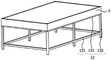
fig. 11 is a schematic structural diagram of a backlight platform according to an embodiment of the present invention;
fig. 12 is a schematic structural diagram of a light transmission assembly according to an embodiment of the present invention.
The figures are labeled as follows:
100-line inspection device;
1-supporting a frame body; 11-a first support frame body; 111-a first beam; 112-a first vertical beam; 113-a first stiffening beam; 12-a second support frame body; 121-a second beam; 122-a second vertical beam; 123-a second stiffening beam; 13-a connector; 131-a sliding part; 1311-a slider; 1312-fixed block; 132-a mounting portion; 14-adjusting the foot; 15-rolling the footing;
2-a three-way motion system; a 21-X direction movement mechanism; 211-a third drive member; 212-a second slide rail; 213-a first transfer lever; 214-a third belt; 215-third slider; 216-universal bearing; 217-a second drive roll; 218-a second driven roller; 219-a mount; 220-a third mount; a 22-Y direction movement mechanism; 221-a first sliding rail; 222-a second drive member; 223-a second slider; 224-a second belt; 225-a first drive roll; 226-a first driven roller; 227-a second mounting frame; a 23-Z motion mechanism; 231-a first driving member; 232-a first gear; 233-a second gear; 234-a first belt; 235-a third gear; 236-a rack; 237-a guide rod; 238-a first slider; 239-a first mounting frame;
3-an inspection module; 31-a positioning assembly; 311-a first mount; 312-a transition piece; 313-a transmitter; 314-universal connection; 32-an inspection assembly; 321-a second mount; 322-inspection piece;
4-a control module; 41-a display member; 42-a controller;
5-a backlight platform; 51-a riser; 52-a light source board; 521-a mounting plate; 522-light source element; 53-a light transmissive component; 531-a support plate; 532-a light diffusion plate; 533-a light-transmitting plate; 534-damping member.
Detailed Description
The present invention will be described in further detail with reference to the accompanying drawings and examples. It is to be understood that the specific embodiments described herein are merely illustrative of the invention and are not limiting of the invention. It should be noted that, for convenience of description, only the structures related to the present invention are shown in the drawings, not the entire structures.
In the description of the present invention, unless otherwise explicitly specified or limited, the terms "connected", "connected" and "fixed" are to be construed broadly, e.g., as being fixedly connected, detachably connected, or integrated; can be mechanically or electrically connected; they may be directly connected or indirectly connected through intervening media, or may be structurally related or interoperable between two elements. The specific meaning of the above terms in the present invention can be understood in specific cases to those skilled in the art.
In the present disclosure, unless expressly stated or limited otherwise, the first feature "on" or "under" the second feature may comprise direct contact between the first and second features, or may comprise contact between the first and second features not directly. Also, the first feature "on," "above" and "over" the second feature may include the first feature being directly above and obliquely above the second feature, or simply indicating that the first feature is at a higher level than the second feature. A first feature being "under," "below," and "beneath" a second feature includes the first feature being directly under and obliquely below the second feature, or simply meaning that the first feature is at a lesser elevation than the second feature.
In the description of the present embodiment, the terms "upper", "lower", "left", "right", and the like are used based on the orientations and positional relationships shown in the drawings, and are only for convenience of description and simplification of operation, but do not indicate or imply that the device or element referred to must have a specific orientation, be constructed and operated in a specific orientation, and thus should not be construed as limiting the present invention. Furthermore, the terms "first" and "second" are used only for descriptive purposes and are not intended to be limiting.
With the development of technology, the production technology of large-sized touch screens is mature, and users are pursuing larger-sized touch screens. The large-size and oversized touch screen can be applied to the fields of touch televisions, smart homes, intelligent education, intelligent commerce, vehicle-mounted display, industrial control, medical treatment and the like. The existing manufacturing process of large-size and oversized touch screens is to screen print or plate a layer of conductive metal, such as silver paste, copper and the like, on a conductive film material, and perform preset pattern etching on the conductive film material printed with the silver paste, so as to match driving programs according to different IC schemes, and achieve the purpose of touch control. The specific etching method can select laser, printing acid-resistant ink or printing etching paste to perform pattern etching according to the actual manufacturing situation. If the short circuit or open circuit occurs in the circuit during the laser etching process, the defective products flow into the following procedures, which results in waste of labor and materials.
As shown in fig. 1 to 11, the present embodiment proposes a line inspection apparatus 100, and the line inspection apparatus 100 is capable of inspecting the connection of a line after etching. The line inspection apparatus 100 further includes a support frame 1, a three-way motion system 2, and an inspection module 3. Wherein, support frame body 1 and be used for bearing and treat the inspection piece, three-way motion system 2 sets up on supporting frame body 1, and inspection module 3 sets up in three-way motion system 2's output. The inspection module 3 comprises an inspection assembly 32, and the three-way motion system 2 can drive the inspection assembly 32 to move so that the inspection assembly 32 inspects the piece to be inspected, and the phenomenon that the piece to be inspected with a flaw flows into the next process or flows into the market to cause material and manual waste is avoided.
For convenience of description, as shown in fig. 1, the length direction of the support frame body 1 is defined as an X direction, the width direction of the support frame body 1 is defined as a Y direction, and the height direction of the support frame body 1 is defined as a Z direction, wherein the X direction, the Y direction, and the Z direction are perpendicular to each other in pairs, and the X direction, the Y direction, and the Z direction only represent a spatial direction and have no substantial meaning.
The detailed structure of the three-way motion system 2 will now be described with reference to fig. 7 to 10.
As shown in fig. 7, the three-way movement system 2 includes an X-direction movement mechanism 21, a Y-direction movement mechanism 22, and a Z-direction movement mechanism 23. The X-direction movement mechanism 21 is used for moving the inspection module 3 in the X direction, the Y-direction movement mechanism 22 is used for moving the inspection module 3 in the Y direction, and the Z-direction movement mechanism 23 is used for moving the inspection module 3 in the Z direction. Drive inspection module 3 through three-way motion system 2 and move along X direction, Y direction and Z direction on supporting frame body 1, realize the automatic inspection of circuit inspection device 100, and three-way motion system 2 simple structure makes the operator flexible operation, is favorable to guaranteeing the reliability of circuit inspection device 100 operation.
The detailed structure of the Z-direction movement mechanism 23 will be described with reference to fig. 8 to 9.
As shown in fig. 8, the Z-direction movement mechanism 23 includes a first driving member 231, a first gear 232, and a second gear 233. The Z-direction moving mechanism 23 is disposed at an output end of the Y-direction moving mechanism 22, an output end of the first driving member 231 is connected to the first gear 232, the first gear 232 and the second gear 233 are disposed at intervals along the Z-direction, the first gear 232 and the second gear 233 tension the first belt 234 together, a diameter of the second gear 233 is larger than a diameter of the first gear 232, the inspection assembly 32 is connected to the second gear 233, when the first driving member 231 works, the first gear 232 can be driven to rotate, the second gear 233 is driven to rotate by movement of the first belt 234, and then the inspection assembly 32 moves in the Z-direction. Through the diameter of the second gear 233 being larger than the diameter of the first gear 232, the first driving member 231 drives the inspection assembly 32 to move at a speed smaller than the output speed of the first driving member 231 in the Z direction, which is beneficial to fine adjustment of the distance from the inspection assembly 32 to the surface of the piece to be inspected and improvement of the definition of the inspection result, meanwhile, the embodiment realizes slow movement of the inspection assembly 32 in the Z direction through a group of gears with different diameters, and the purpose of speed reduction is realized by adopting a simple structure, which is beneficial to reducing the cost of the line inspection device 100. In this embodiment, the output end of the first driving member 231 is connected to the first gear 232, so that the output of the first driving member 231 along the Y direction is converted into the movement of the inspection assembly 32 in the Z direction, and the connection structure is simple and is beneficial to reducing the assembly space occupied by the Z-direction movement mechanism 23.
Specifically, the first driving member 231 is fixed on the Y-direction moving mechanism 22 through the first mounting frame 239, which is beneficial to improving the movement stability of the Z-direction moving mechanism 23. Preferably, the first driving member 231 is preferably a stepping motor, which has better start-stop and reverse response, and is beneficial for an operator to drive the inspection assembly 32 to move or pause along the Z direction at any time according to the distance between the inspection assembly 32 and the member to be inspected, and meanwhile, the stepping motor has better stability performance under low-speed movement, and is suitable for low-speed fine adjustment of the inspection assembly 32 in the Z direction in the embodiment. Illustratively, the first belt 234 is preferably a synchronous belt, which operates without slip, and is advantageous to ensure accurate transmission of the gear ratios of the first gear 232 and the second gear 233, thereby improving the accuracy of the Z-direction movement of the inspection assembly 32.
Preferably, as shown in fig. 9, the Z-direction moving mechanism 23 further includes a third gear 235 and a rack 236, the third gear 235 and the second gear 233 are coaxially disposed, the rack 236 extends in the Z direction, the third gear 235 is engaged with the rack 236, and the inspection assembly 32 is connected to the rack 236. Through third gear 235 and rack 236 meshing, be favorable to improving the stable control that inspection module 3 was adjusted in the Z direction motion, make things convenient for the operator to adjust the distance of inspection subassembly 32 to the piece of examining, improve the definition of inspection subassembly 32 inspection result.
Preferably, as shown in fig. 8 and 9, the Z-direction moving mechanism 23 further includes a guide rod 237 and a first sliding block 238, the guide rod 237 is fixed on the first mounting frame 239 along the Z-direction, and the first sliding block 238 is sleeved outside the guide rod 237 and can slide along the extending direction of the guide rod 237. Through the cooperation of the guide rod 237 and the first slider 238, the checking assembly 32 is constrained to move along the extending direction of the guide rod 237, so that the torsion is avoided, and the checking precision of the checking assembly 32 is ensured.
The detailed structure of the Y-direction moving mechanism 22 will now be described with reference to fig. 10.
As shown in fig. 10, the Y-direction moving mechanism 22 includes a second driving member 222, a first driving roller 225, a first driven roller 226, and a second belt 224. The first driving roller 225 is connected to an output end of the second driving element 222, the first driven roller 226 and the first driving roller 225 jointly tension the second belt 224, and the first driven roller 226 and the first driving roller 225 are arranged at intervals along the Y direction. Through the connection relationship among the second driving member 222, the first driving roller 225, the first driven roller 226 and the second belt 224, the space occupied by the Y-direction movement mechanism 22 is saved, and meanwhile, the second belt 224 is connected to realize movement in a larger stroke range, so that the structure is simple, and the application range of the line inspection device 100 is improved. Specifically, the second driving element 222 can be a servo motor, which has better control precision and high-speed performance, and the low-speed motion of the servo motor is stable. Illustratively, the second belt 224 is preferably a synchronous belt, which is a mesh transmission, and the synchronous belt is a non-slip synchronous transmission, so that the transmission efficiency is high, and can be generally up to 0.98. The synchronous belt can realize power transmission on a larger stroke, and compared with a triangular belt, the synchronous belt has an obvious energy-saving effect.
Specifically, as shown in fig. 10, the Y-direction moving mechanism 22 further includes two sets of second mounting brackets 227, the two sets of second mounting brackets 227 are respectively fixed at two ends of the extending direction of the Y-direction moving mechanism 22, the first driving roller 225 and the first driven roller 226 are respectively pivoted with the corresponding second mounting brackets 227, and the second mounting brackets 227 are used for mounting and fixing the first driving roller 225 and the first driven roller 226, so as to ensure the stability of the movement of the first driving roller 225 and the first driven roller 226, and to be beneficial for ensuring the stable operation of the Y-direction moving mechanism 22.
Preferably, the Y-direction moving mechanism 22 further includes a first sliding rail 221 and a second sliding block 223, the first sliding rail 221 extends along the Y direction and is disposed on the X-direction moving mechanism 21, the second sliding block 223 is fixed on the second belt 224 and is connected to the Z-direction moving mechanism 23, and the second sliding block 223 is connected to the first sliding rail 221 in a sliding manner. Through the sliding fit of the first slide rail 221 and the second slide block 223, the inspection assembly 32 can move along the Y direction all the time, and the influence on the accuracy of the inspection result of the inspection assembly 32 due to deflection is avoided.
The detailed structure of the X-direction moving mechanism 21 will now be described with reference to fig. 10.
As shown in fig. 10, the X-direction moving mechanism 21 includes a third driving element 211 and a third transmission assembly, the third transmission assembly is connected to an output end of the third driving element 211, and the third driving element 211 drives the Y-direction moving mechanism 22 to move along the X direction through the first transmission assembly, so as to realize the movement of the inspection assembly 32 in the X direction. Through the cooperation of the X-direction movement mechanism 21 and the Y-direction movement mechanism 22, the operator can control the movement of the checking assembly 32 within the travel range of the three-way movement system 2, which is beneficial for the operator to control the precision of the movement position of the checking assembly 32. Specifically, the third driving element 211 is preferably a servo motor, which has good control precision and high-speed performance, and the low-speed motion of the servo motor is smooth.
Preferably, as shown in fig. 10, the first driving assembly includes a second driving roller 217, a second driven roller 218, and a third belt 214. The second driving roller 217 is connected to an output end of the third driving element 211, the second driven roller 218 and the second driving roller 217 jointly tension the third belt 214, and the second driven roller 218 and the second driving roller 217 are arranged at an interval in the X direction, which is beneficial to expanding a movement stroke of the inspection assembly 32 in the X direction, thereby being beneficial to enabling the line inspection device 100 to be applicable to the field of line inspection of large-sized lines and oversized lines. Illustratively, the third belt 214 is preferably a synchronous belt, which facilitates the improvement of the movement efficiency of the line inspection device 100 in the X direction, and the synchronous belt facilitates maintenance.
Further, as shown in fig. 10, the first transmission assembly further includes a third mounting bracket 220, the third mounting bracket 220 is fixedly disposed at a corresponding position of the second driven roller 218, and the second driven roller 218 is pivotally connected to the third mounting bracket 220, so as to improve the motion stability of the second driven roller 218.
As shown in fig. 10, the first transmission assemblies are two sets, and the second driving rollers 217 of the two sets of first transmission assemblies are coaxially disposed through the first transmission rod 213. Through first drive rod 213, connect two sets of first drive components to drive Y under the drive of same third driving piece 211 and move to moving mechanism 22 at X, simple structure is favorable to reducing the cost of circuit inspection device 100, and is favorable to guaranteeing that two sets of first drive components can synchronous motion, improves the reliability of the operation of circuit inspection device 100, and then guarantees the accuracy nature of circuit inspection device 100 inspection result. Meanwhile, the two groups of first transmission assemblies are arranged in parallel, so that the stability of the movement of the inspection assembly 32 in the X direction can be ensured.
Preferably, as shown in fig. 10, the first transmission assembly further includes a second slide rail 212 and a third slide block 215. The second slide rail 212 is disposed on the first support frame 11 along the X direction, the third slide block 215 is fixed on the third belt 214 and connected to the Y-direction moving mechanism 22, and the third slide block 215 is slidably connected to the second slide rail 212, so that the Y-direction moving mechanism 22 always moves along the first slide rail 221 in the X direction, thereby preventing the Y-direction moving mechanism 22 from deflecting during the moving process, and facilitating to ensure the effective operation of the line inspection apparatus 100.
Preferably, as shown in fig. 10, the first transmission assembly further includes two mounting seats 219 and a universal bearing 216, two mounting seats 219 are spaced below the first transmission rod 213, and the universal bearing 216 is disposed between the first transmission rod 213 and the corresponding mounting seats 219. The universal bearing 216 can prevent the first transmission rod 213 from being worn by the torque generated by the installation error at the two ends of the first transmission rod 213, which is beneficial to prolonging the service life of the first transmission rod 213 and further prolonging the service life of the circuit inspection device 100.
More preferably, as shown in fig. 1, the line inspection apparatus 100 further includes a control module 4, the control module 4 is disposed on the support frame 1, and the control module 4 can obtain the inspection result information of the inspection module 3. The inspection result obtained by the control module 4 is convenient for an operator to perform later analysis on the inspection result.
The control module 4 will now be described with reference to fig. 1.
Further, as shown in fig. 1, the control module 4 includes a display 41, the display 41 is electrically connected to the inspection module 3, and the display 41 can display the inspection result of the inspection module 3. The operator can directly judge whether the current checking position is the position required by the operator according to the checking result displayed on the display part 41, meanwhile, the operator can judge whether the distance between the checking component 32 and the part to be checked is proper or not by checking the display result of the display part 41, and the operator can judge whether to continuously adjust the height of the checking component 32 or not according to the display result.
More preferably, as shown in fig. 1, the control module 4 further includes a controller 42, the controller 42 can control the movement of the three-way motion system 2, and then control the specific position of the inspection module 3 in the three directions of the X direction, the Y direction and the Z direction, so that the operator can conveniently control the specific position of the inspection through the controller 42, the flexibility of the operation of the line inspection device is improved, the working efficiency of the operator is improved, and the fault probability of the line inspection device is reduced. Specifically, an operator can set 10 sets of point locations on the controller 42 in advance according to the type and working experience of the piece to be inspected, so that the line inspection device 100 can conveniently and quickly move the inspection assembly 32 to the point locations to check line defects, and the working efficiency of the operator is improved. Of course, the number of preset point locations may also be adjusted according to the actual situation, which is not limited in this embodiment.
However, the conventional circuit inspection apparatus 100 in the prior art cannot determine the position of the inspection module 3 during the inspection process, which may result in missing of the inspection result, and when an operator wants to inspect a specific position, the operator can only roughly determine according to the position of the inspection module 3, and cannot determine whether the target position has been accurately located.
In order to solve the above problem, as shown in fig. 2, the inspection module 3 in the present embodiment further includes a positioning component 31, the positioning component 31 is disposed at the output end of the three-way movement system 2, and the positioning component 31 can indicate the inspection position of the inspection component 32. When the circuit inspection device 100 inspects a to-be-inspected object, the position of the positioning component 31 is adjusted, so that the positioning component 31 can emit signals such as laser and the laser can be directed to the central position inspected by the circuit inspection device 100. If an operator wants to check a certain determined position, the three-way movement system 2 is operated to drive the positioning component 31 to move, so that the laser points to the position to be checked, and then the checking component 32 is positioned right above the position to be checked to check, so that the precise positioning of the position to be checked is realized, and the accuracy of the checking result of the line checking device 100 is improved. Especially for large-size and oversized pieces to be inspected, because the area of the pieces to be inspected is large, an operator cannot accurately determine the inspection position through vision, and the positioning assembly 31 indicates the inspection position for the operator, so that the line inspection device 100 is beneficial to ensuring the accurate positioning of the inspection position of the large-size and oversized pieces to be inspected, and the accuracy of the inspection result of the line inspection device 100 is improved. Meanwhile, the positioning assembly 31 has a simple structure and low cost, and is helpful for reducing the fault probability of the line inspection device 100 and improving the operation reliability of the line inspection device 100.
The specific structure of the positioning assembly 31 will now be described with reference to fig. 2.
As shown in fig. 2, the positioning assembly 31 includes a first mounting part 311 and a transmitter 313, one end of the first mounting part 311 is connected to the output end of the three-way movement system 2, and the transmitter 313 is disposed on the first mounting part 311. When the device works, the positioning of the inspection position of the piece to be inspected can be completed only by adjusting the light emitting direction of the emitter 313, so that the device is convenient for operators to operate and improves the working efficiency of the operators.
As shown in fig. 2, the positioning assembly 31 further includes a universal connection 314 and a transition piece 312, the universal connection 314 is installed at the connection positions of the transition piece 312 and the emitter 313 and the connection positions of the transition piece 312 and the first mounting piece 311, so that the angle adjustment of the emitter 313 is not limited by the mechanical connection position, and the light emitted by the emitter 313 can point to any direction, thereby increasing the positioning area of the positioning assembly 31 and further increasing the application range of the line inspection device 100. Specifically, universal connector 314 includes spherical universal rotation portion and cylindrical connecting rod portion, fixed connection between connecting rod portion and the universal rotation portion, and transition piece 312 is relative two sheet structures that set up and interconnect, is provided with the arc recess in two sheet structures one side each other relative, and the arc recess is used for holding universal rotation portion, and the free end of connecting rod portion is connected with transmitter 313 or first installed part 311. Through the rotation of the universal rotating part in any direction in the transition piece 312, the emitter 313 can emit light rays in any direction, so that when the inspection assembly 32 is at any distance from the piece to be inspected, the emitter 313 can emit light rays pointing to the inspection center of the inspection assembly 32.
The specific structure of the inspection unit 32 will now be described with reference to fig. 2.
As shown in fig. 2, the inspection assembly 32 includes a second mounting part 321 and an inspection piece 322, the second mounting part 321 is connected to the output end of the three-way movement system 2, and the inspection piece 322 is disposed on the second mounting part 321. Since the inspection member 322 has a plurality of wearing members, the inspection member 322 is detachably connected to the output end of the three-way moving system 2 through the second mounting member 321, thereby facilitating the maintenance and replacement of the inspection member by an operator. Specifically, the inspection object 322 is preferably a camera, and the camera is driven to move by the three-way motion system 2, and the focal length of the camera is adjusted, so that the object to be inspected, which is shot by the camera, can be clearer.
The specific structure of the support frame 1 will now be described with reference to fig. 3 to 6.
In the prior art, a conventional circuit inspection device generally includes a bearing frame and an inspection module disposed on the bearing frame, wherein the bearing frame can bear a to-be-inspected object, and the inspection module is used for detecting performance of the to-be-inspected object on the bearing frame. This construction is suitable for smaller sizes of the items to be inspected, i.e. the size of the carriage is also smaller. However, the size of the existing capacitive touch screen is larger and larger, so that the size of the bearing frame is larger, the installation and maintenance are troublesome, the weight is larger, and the transportation is inconvenient.
In order to solve the above problem, as shown in fig. 3, the support frame 1 of the present embodiment includes a first support frame 11 and a second support frame 12, the second support frame 12 is embedded in the first support frame 11, the second support frame 12 is detachably connected to the first support frame 11, in the present embodiment, the three-way movement system 2 is disposed on the first support frame 11, and the second support frame 12 is used for carrying a to-be-inspected member. In addition, the relative position of first support frame body 11 and second support frame body 12 is adjustable to adjust the distance between inspection module 3 and the piece of examining, and first support frame body 11 and second support frame body 12 simple structure, easy to assemble and maintenance, the components of a whole that can function independently structural design is favorable to reducing machining precision and installation accuracy requirement simultaneously, reduce the processing cost of circuit inspection device 100, reduce the probability that circuit inspection device 100 breaks down, and then improve the reliability of circuit inspection device 100 operation. After the inspection of the to-be-inspected member is completed, the second support frame body 12 can be detached from the first support frame body 11 for separate transportation and storage, so that the occupied space can be reduced.
As a preferable scheme, as shown in fig. 3 and 4, the support frame body 1 further includes a connection member 13, and the connection member 13 is disposed on one of the first support frame body 11 and the second support frame body 12 and can slide relative to the other, so that the relative height between the first support frame body 11 and the second support frame body 12 is adjustable. Preferably, the number of the connecting members 13 is plural, the plurality of connecting members 13 are arranged at intervals along the circumferential direction of the second support frame body 12, and the second support frame body 12 is slidably connected with the first support frame body 11 through the plurality of connecting members 13. Particularly, for the line inspection apparatus 100 for inspecting large-sized and oversized pieces to be inspected, when the movement plane of the inspection assembly 32 is not parallel to the support plane of the second support frame 12, the movement plane of the inspection assembly 32 may be made parallel to the support plane of the second support frame 12 by adjusting the connecting member 13 at the corresponding position, and the inspection assembly 32 can ensure that the focusing is always clear when inspecting the pieces to be inspected to obtain the inspection result, thereby improving the accuracy of the inspection result of the line inspection apparatus 100. Specifically, the connecting member 13 may be fixedly disposed on the first support frame body 11, and the second support frame body 12 is slidably connected to the connecting member 13, so as to adjust the height between the first support frame body 11 and the second support frame body 12. In other embodiments, the connecting member 13 may also be fixedly disposed on the second support frame body 12, and the first support frame body 11 is slidably connected to the connecting member 13, so as to adjust the height between the first support frame body 11 and the second support frame body 12.
The detailed structure of the connecting member 13 will now be described with reference to fig. 4.
Specifically, as shown in fig. 4, the link 13 includes a sliding portion 131 and a mounting portion 132. Now, taking the example that the connecting member 13 is fixedly disposed on the first support frame 11 as an example, the second support frame 12 is disposed through the sliding portion 131 and can slide up and down relative to the sliding portion 131, one end of the mounting portion 132 is connected to the first support frame 11, and the other end is fixed to the sliding portion 131, so that the connection manner is simple and the mounting by an operator is convenient.
More preferably, as shown in fig. 4, the sliding part 131 includes a sliding block 1311 and a fixing block 1312, the sliding block 1311 is of a U-shaped structure, a sliding groove is formed in the sliding block 1311 of the U-shaped structure, and two free ends of an opening of the U-shaped structure extend outwards to form the fixing block 1312. The second support frame body 12 is slidably disposed in the sliding groove of the sliding block 1311, so that the second support frame body 12 can slide in the sliding groove along the vertical direction, and the fixing block 1312 can be connected with the mounting portion 132 through a bolt, and is simple in structure and convenient for an operator to detach.
Further, as shown in fig. 4, the mounting portion 132 is configured as an L-shaped structure, and the mounting portion 132 of the L-shaped structure includes a first extending block and a second extending block extending along two mutually perpendicular directions, wherein the first extending block is fixedly connected to the fixing block 1312 for restricting the relative positions of the second support frame body 12 and the first support frame body 11 in the horizontal direction. The second extension block is provided with a strip-shaped groove extending along the direction perpendicular to the first extension block, the connecting bolt can penetrate through the strip-shaped groove and be fixed on the first support frame body 11, and the connecting bolt can slide along the groove wall of the strip-shaped groove, so that the relative positions of the first support frame body 11 and the second support frame body 12 can be adjusted along the direction of the strip-shaped groove, and the situation that the first support frame body 11 and the second support frame body 12 cannot be assembled due to machining accuracy errors is avoided.
As a preferable scheme, as shown in fig. 4, the support frame 1 further includes an adjusting foot 14, the adjusting foot 14 may be disposed on the first support frame 11, and the adjusting foot 14 is used for adjusting the height of the first support frame 11, so that the sliding block 1311 can slide along the second support frame 12 in the vertical direction. The adjusting bottom foot 14 has simple structure, convenient processing and low cost, and is convenient for operators to operate. The adjusting feet 14 are matched with the connecting pieces 13 to adjust the relative positions of the first supporting frame body 11 and the second supporting frame body 12 in the vertical direction, so that the parallelism of the three-way movement system 2 on the first supporting frame body 11 and the working plane of the second supporting frame body 12 is adjusted, and the accuracy of the inspection result of the line inspection device 100 is improved. In other embodiments, the adjusting feet 14 may also be disposed on the second support frame body 12, and the adjusting feet 14 are used to adjust the height of the second support frame body 12, so that the second support frame body 12 can slide in the sliding groove along the vertical direction, thereby adjusting the heights of different positions of the second support frame body 12. In other embodiments, the first support frame body 11 and the second support frame body 12 are both provided with the adjusting feet 14, the adjusting feet 14 are used for adjusting the height of the corresponding first support frame body 11 or the second support frame body 12, and the height of the first support frame body 11 and the height of the second support frame body 12 can be adjusted, so that the range of height adjustment of the support frame body 1 is increased, and the parallelism between the movement plane of the inspection assembly 32 and the working plane of the second support frame body 12 can be adjusted more conveniently.
As a preferable scheme, the adjusting range of the adjusting feet 14 is-100 mm, and the relative height of the first supporting frame body 11 and the second supporting frame body 12 can be adjusted within-100 mm. Preferably, the adjusting range of the adjusting feet 14 is-50 mm to 50mm, so that the heights of the first support frame body 11 and the second support frame body 12 are adjusted within a small range, thereby avoiding the contact with the support plane of the second support frame body 12 when the inspection assembly 32 is adjusted due to an excessively large adjusting range, and avoiding the damage to the inspection assembly 32.
More preferably, the support frame body 1 further comprises a rolling foot 15, the rolling foot 15 can be arranged at the bottom of the first support frame body 11, and the rolling foot 15 can drive the first support frame body 11 to move, so that an operator can conveniently move the first support frame body 11 to a proper operation position, and time and labor are saved. In other embodiments, the rolling feet 15 may be further disposed at the bottom of the second support frame 12, the rolling feet 15 may drive the second support frame 12 to move, and the rolling feet 15 are disposed at the bottom of the second support frame 12, so that the operator can move and transport the second support frame 12 conveniently, and convenience is provided for the operator to install the second support frame. In other embodiments, rolling feet 15 may be disposed at the bottom of the first support frame body 11 and the bottom of the second support frame body 12, so that the rolling feet 15 can drive the first support frame body 11 and the second support frame body 12 to move, which is convenient for an operator to move the support frame body 1 to a proper position for operation.
The detailed structure of the first support frame 11 will now be described with reference to fig. 5.
As shown in fig. 5, the first support frame 11 is a detachable structure, which is convenient for an operator to transport and install. Further, the first support frame 11 includes a plurality of first frame-shaped structures and a plurality of first vertical beams 112, the plurality of first frame-shaped structures are parallel and spaced apart from each other along the vertical direction, each first frame-shaped structure includes a plurality of first cross beams 111 connected in sequence from head to tail, the plurality of first vertical beams 112 are spaced apart from each other along the circumferential direction of the first frame-shaped structures, and each first vertical beam 112 is connected to each first vertical beam 112. The plurality of first frame-shaped structures is advantageous for ensuring the stability of the first support frame 11. In this embodiment, the first support frame body 11 can be used for installing the three-way movement system 2, and along with waiting to inspect a size increase, the stroke range increase and the weight increase of the three-way movement system 2, in order to stably bear the three-way movement system 2 of great weight, through setting up a plurality of first frame-shaped structures and a plurality of first vertical beams 112, can avoid first support frame body 11 to take place distortion, further improves the stability of first support frame body 11. Alternatively, the number of the first vertical beams 112 may be four, and four first vertical beams 112 are respectively located at four corners of the first frame-shaped structure; as shown in fig. 5, in the present embodiment, the number of the first vertical beams 112 is six, wherein four first vertical beams 112 are respectively located at four corners of the first frame-shaped structure, and the other two first vertical beams 112 are respectively located between two first vertical beams 112 arranged along the length direction of the first cross beam 111 with a longer length, so as to prevent the middle of the first cross beam 111 with a longer length from being recessed.
As shown in fig. 5, the first support frame 11 further includes a first reinforcing beam 113, two ends of the first reinforcing beam 113 are respectively connected to the first vertical beams 112, so as to strengthen and support the two first vertical beams 112, and further improve the stability of the first support frame 11. In other embodiments, both ends of the first reinforcing beam 113 may be connected to the first cross beam 111, and the first cross beam 111 is connected to the first vertical beam 112, so that the stability of the first support frame body 11 can be enhanced by the first reinforcing beam 113.
As a preferred scheme, the first supporting frame body 11 is made of an aluminum alloy material. The aluminum alloy material has light weight and low cost.
The detailed structure of the second support frame 12 will now be described with reference to fig. 6.
As shown in fig. 6, the second support frame 12 includes a second frame structure and a plurality of second vertical beams 122, the second frame structure includes a plurality of second cross beams 121 connected end to end in sequence, the plurality of second vertical beams 122 are arranged along the circumferential direction of the second frame structure at intervals, and each second vertical beam 122 is connected to the second frame structure. The second frame structure is supported by the plurality of second vertical beams 122, so that the stability of the second support frame body 12 is effectively ensured.
Preferably, the second vertical beams 122 are welded to the corresponding second horizontal beams 121. In this embodiment, the second support frame body 12 is used for carrying the to-be-inspected member, and the second vertical beam 122 and the second cross beam 121 are correspondingly welded by welding, which is favorable for ensuring the stability and structural strength of the second support frame body 12.
Preferably, the second support frame 12 is made of stainless steel, which has high strength and deformation resistance, and is helpful for improving the stability of the second support frame 12. Since the second support frame 12 is used to arrange the member to be inspected, the stability of the second support frame 12 is important for the line inspection apparatus 100.
The detailed structure of the backlight platform 5 will now be described with reference to fig. 11 and 12.
Fig. 11 is a schematic structural diagram of the backlight platform provided in the embodiment of the present invention, as shown in fig. 11, the circuit inspection apparatus 100 further includes a backlight platform 5, the backlight platform 5 is disposed on the support frame 1, and the backlight platform 5 can provide backlight for the to-be-inspected member. The definition of the shooting result of the inspection component 32 to the inspection piece is improved through the backlight, so that the accuracy of the inspection result of the line inspection device 100 is ensured.
As shown in fig. 11, the backlight platform 5 includes light source board 52, printing opacity subassembly 53 and a plurality of riser 51 that end to end connects gradually, and light source board 52 level sets up, and light source board 52 is located the below of riser 51 and is connected in order to enclose with a plurality of risers 51 and establish and form the box structure, and the upper shed of box structure is located to printing opacity subassembly 53 lid, bears on the printing opacity subassembly 53 and treats the inspection piece to project the light of light source board 52 on treating the inspection piece. The backlight platform 5 of the embodiment has a simple structure, and is beneficial to reducing the cost of the circuit inspection device 100.
In the prior art, a conventional circuit inspection apparatus is provided with a backlight platform, a to-be-inspected object is placed on the backlight platform, and backlight is provided through the backlight platform to perform circuit inspection. At present, transparent glass is generally selected as a light transmission component of a commonly used backlight platform, a light source part provides a point light source, and the transparent glass irradiates the point light source on a part to be inspected. Due to the fact that the point light source from the backlight platform irradiates unevenly, for large-size and ultra-large-size touch screen line inspection, backlight from the point light source penetrates through an element to be inspected unevenly on the back face of the element to be inspected, and the line inspection device cannot image clearly in places with too bright or too dark light, so that accuracy of inspection results of the line inspection device is affected.
In order to solve the above problem, as shown in fig. 11, the light-transmitting member 53 of the backlight stage 5 in the present embodiment can convert the point light source of the light source plate 52 into a surface light source. The uniformity of the backlight of the part to be inspected helps the inspection assembly 32 to be able to take a clear picture for analysis by the operator.
The structure of the light transmission member 53 will now be described in detail with reference to fig. 12.
More preferably, as shown in fig. 12, the light transmission member 53 includes a light diffusion plate 532 and a light-transmitting plate 533, the light diffusion plate 532 being laid on the riser 51, and the light-transmitting plate 533 being laid on the light diffusion plate 532. The light diffuser plate 532 can uniformly diffuse the light source from the light source plate 52 over the entire plane of the backlight platform 5 to provide uniform backlight for the part to be inspected. Specifically, the light-transmitting plate 532 may be a white acrylic plate, which has the advantages of low cost and light weight, and the white acrylic plate makes the display background of the circuit inspection apparatus 100 white, so as to enhance the uniformity of the bottom light source. More preferably, the light diffusion sheet 532 has a thickness of 1mm in order to reduce the weight of the light transmission member 53. The light-transmitting plate 533 can transmit the light source from the light source plate 52, and the light-transmitting plate 533 can improve the strength of the light-transmitting component 53 for supporting the object to be supported. More preferably, in order to improve the strength of the light-transmitting plate 533, the thickness of the light-transmitting plate 533 is preferably 12mm.
As a preferable scheme, as shown in fig. 12, the light-transmitting plate 533 may be made of a tempered material, and the ground glass or sandblasted glass made of the tempered material has better rigidity and strength, so that the risk of damage when the light-transmitting component 53 bears a large-size or oversized part to be inspected can be avoided, and the service life of the circuit inspection device 100 can be prolonged.
Since the thickness of the light-transmitting plate 532 is only 1mm, the size of the line inspection apparatus 100 is very large in this embodiment, and the light-transmitting plate 532 is thin and the middle recess is easily generated. In order to avoid this, as shown in fig. 12, the light transmitting member 53 further includes a support plate 531, the support plate 531 being disposed between the riser 51 and the light diffusion plate 532, the support plate 531 being capable of stably supporting the light diffusion plate 531. Specifically, the support plate 531 is preferably made of transparent tempered glass, which transmits the light source from the light source plate 52 as much as possible, and the tempered glass has high rigidity and strength and has a good supporting function for the light diffusion plate 532. Preferably, the strength of the tempered glass plate with the thickness of the support plate 531 of 5mm,5mm meets the support requirement, and the thickness is moderate, so that the support plate 531 is prevented from being too thick and increasing the weight of the light-transmitting component 53, and meanwhile, the support plate 531 is prevented from being too thin and insufficient in support force.
Preferably, as shown in fig. 12, in order to enhance the connection strength between the support plate 531 and the riser 51, the light-transmitting component 53 further includes a shock-absorbing member 534, and the shock-absorbing member 534 is located between the support plate 531 and the riser 51, so as to improve the stability of the backlight platform 5. Specifically, the cushioning member 534 is preferably thick foam, which has a cushioning and cushioning effect. The dampers 534 are provided specifically at positions where the support plates 531 contact the risers 51. Specifically, the cushioning member 534 is preferably a thick foam having good sealing and cushioning properties. Further, the thickness of the foam is preferably 4mm, and since the support plate 531, the light diffusion plate 532 and the light transmission plate 533 have large weights, the too thin foam has insufficient buffering and damping effects, and the foam with the thickness of 4mm meets the application requirements and is low in cost.
As a preferable mode, as shown in fig. 11, the light source board 52 includes a mounting board 521, a light source member 522, a variable resistor, and a light source control member. The light source 522 is arranged on the mounting plate 521, the variable resistor is connected with the light source 522, the light source control assembly is electrically connected with the light source 522 and the variable resistor, and the light source control assembly can adjust the brightness of the light source 522 through the variable resistor. The back of the piece to be inspected is polished, the backlight is used for displaying the outline of the opaque object, the sensitivity of the whole pattern is influenced by the adjustment of the light source 522, and the operator can adjust the effect of the strongest black-white contrast. By adjusting the brightness of the light source 522, the circuit inspection device 100 can adapt to different working environments, and the application range of the circuit inspection device 100 is improved.
The traditional fluorescent tube is also called as fluorescent lamp, two ends of the lamp are respectively provided with a filament, the tube is filled with trace argon and rarefied mercury vapor, the inner wall of the tube is coated with fluorescent powder, and when the gas between the two filaments is conductive, the gas emits ultraviolet rays, so that the fluorescent powder emits visible light. Because of containing heavy metal pollutant mercury, the discarded fluorescent lamp tube has serious pollution to the environment. Preferably, the light source unit 522 includes a plurality of LED lights arranged in a linear array, the plurality of LED lights configured to provide a light source. The LED luminous body adopts the light emitting diode as a light source, so that the luminous efficiency is higher, the energy is more saved, the service life is longer, and the LED luminous body is more environment-friendly.
Further, the light source 522 further comprises a diffusion cover, the diffusion cover covers the LED light emitting body, and the diffusion cover can uniformly diffuse light spots of a point light source emitted by the LED light emitting body, so as to avoid unevenness of a light source of the backlight platform 5. Specifically, the preferred select is the milky white diffusion cover, and the general transmittance of this kind of shell is 83% -85%, and the facula of LED luminous element can not be seen to the transmittance below 83%.
Preferably, as shown in fig. 11, the light source units 522 include a plurality of groups, and the plurality of groups of light source units 522 are arranged on the mounting plate 521 in an array. The light sources arranged in an array manner are provided on the larger plane through the multiple groups of light source elements 522, so that the backlight platform 5 is ensured to integrally provide backlight with uniform light, and the problem that local light of the backlight platform 5 is insufficient when the backlight platform 5 is applied to the large-size or oversized circuit inspection field is avoided.
Further, the light intensity range of the scattered light of the light-transmitting component 53 is 500Lux to 2000Lux, which is beneficial to ensuring that the light provided by the backlight platform 5 can enable the inspection piece 322 to shoot a clear inspection result. Preferably, the intensity of the upper surface of the light-transmitting component 53 of the backlight platform 5 is more than 1200Lux, so as to provide sufficient backlight for the inspection component 32 and better ensure the definition of the inspection result.
As a preferable scheme, as shown in fig. 11, the length of the backlight platform 5 is 300mm to 3500mm, and the width thereof is 200mm to 3000mm, so that a large-sized or ultra-large-sized object to be inspected can be carried, and the application range of the circuit inspection device 100 is increased. Specifically, the line inspection apparatus 100 of the present embodiment can be applied to all of the to-be-inspected members having an area size of less than 120 inches.
The specific working process of this embodiment is as follows:
in operation, as shown in fig. 1 and 3, the adjusting feet 14 are first screwed to enable the first support frame 11 to be height-adjusted in the Z direction relative to the second support frame 12, so that the upper surface of the backlight platform 5 disposed on the second support frame 12 is parallel to the movement plane of the three-way movement system 2, and then the to-be-inspected object is placed on the backlight platform 5.
As shown in fig. 8, an operator starts the first driving member 231 to rotate the first gear 232, so as to drive the second gear 233 to rotate, the second gear 233 drives the third gear 235 to rotate, the driving rack 236 slides along the Z direction, so as to drive the inspection assembly 32 to approach or leave the to-be-inspected member in the Z direction, and the operator adjusts the distance between the inspection assembly 32 and the to-be-inspected member to a proper position by looking at the display result condition on the display member 41.
As shown in fig. 2, the operator adjusts the position indicated by the light emitted from the positioning assembly 31 so as to correspond to the center position inspected by the inspection assembly 32.
An operator presets 10 point positions in the controller 42 according to work experience, then the three-way movement system 2 is started to firstly check the preset 10 point positions, and the operator can conveniently check the checking result.
As shown in fig. 1, the operator controls the specific position inspected by the inspection assembly 32 through the X-direction moving mechanism 21 and the Y-direction moving mechanism 22 according to the inspection result, and then inspects other positions of the object to be inspected.
By the method, an operator can obtain a plurality of groups of photos for displaying the line condition of the piece to be inspected, and the operator analyzes the photos to obtain the result of the line quality condition.
It is noted that the basic principles and main features of the present invention and the advantages of the present invention have been shown and described above. It will be understood by those skilled in the art that the present invention is not limited to the embodiments described above, which are given by way of illustration only, and that various changes and modifications may be made without departing from the spirit and scope of the invention as defined by the appended claims and their equivalents.
Claims (10)
1. A three-way motion system, comprising:
an X-direction movement mechanism (21) configured to drive the movement member to move in the X direction;
a Y-direction moving mechanism (22) configured to drive the moving member to move in a Y direction; and
z is to motion (23), including first driving piece (231), first gear (232), second gear (233) and first belt (234), the output of first driving piece (231) with first gear (232) are connected, first gear (232) with common tensioning of second gear (233) first belt (234), the diameter of second gear (233) is greater than the diameter of first gear (232), the motion sets up on second gear (233), Z is to motion (23) can drive the motion moves in the Z direction, the X direction the Y direction reaches two liang mutually perpendicular in the Z direction.
2. Three-way movement system according to claim 1, wherein the Z-movement mechanism (23) further comprises a third gear (235) and a rack (236), the third gear (235) and the second gear (233) being coaxially arranged, the rack (236) extending in the Z-direction, and the third gear (235) being engaged with the rack (236), the movement member being connected with the rack (236).
3. Three-way movement system according to claim 1 or 2, wherein the Y-movement mechanism (22) comprises:
a second driver (222);
a first drive roller (225), the first drive roller (225) being connected to an output of the second drive (222); and
a first driven roller (226) and a second belt (224), the first driven roller (226) and the first driving roller (225) jointly tension the second belt (224), and the first driven roller (226) and the first driving roller (225) are arranged at intervals along the Y direction.
4. A three-way kinematic system according to claim 3, characterized in that said Y-directional kinematic mechanism (22) further comprises:
a first slide rail (221), the first slide rail (221) extending along the Y-direction; and
the first sliding block (223) is fixed on the second belt (224) and connected with the Z-direction movement mechanism (23), and the first sliding block (223) is connected with the first sliding rail (221) in a sliding mode.
5. Three-way movement system according to claim 1 or 2, wherein the X-movement mechanism (21) comprises:
a third driver (211); and
and the third transmission assembly is connected with the output end of the third driving piece (211), and the third driving piece (211) drives the Y-direction movement mechanism (22) to move along the X direction through the first transmission assembly.
6. The three-way motion system of claim 5, wherein the first transmission assembly comprises:
the second driving roller (217) is connected with the output end of the third driving piece (211); and
a second driven roller (218) and a third belt (214), wherein the second driven roller (218) and the second driving roller (217) jointly tension the third belt (214), and the second driven roller (218) and the second driving roller (217) are arranged at intervals along the X direction.
7. Three-way movement system according to claim 6, wherein the first transmission assemblies are in two groups, the second drive rollers (217) of the two groups of first transmission assemblies being coaxially arranged by means of a first transmission rod (213).
8. The three-way motion system of claim 6, wherein the first transmission assembly further comprises:
a second slide rail (212), the second slide rail (212) disposed along the X direction; and
and the second sliding block (215) is fixed on the third belt (214) and connected with the Y-direction movement mechanism (22), and the second sliding block (215) is connected with the second sliding rail (212) in a sliding manner.
9. The three-way motion system of claim 7, wherein the first transmission assembly further comprises:
two mounting seats (219) are arranged below the first transmission rod (213) at intervals;
and the universal bearings (216) are arranged between the first transmission rod (213) and the corresponding mounting seats (219).
10. A line detection device comprising the three-way motion system of any one of claims 1 to 9.
Priority Applications (1)
| Application Number | Priority Date | Filing Date | Title |
|---|---|---|---|
| CN202121512517.0U CN217542918U (en) | 2021-07-05 | 2021-07-05 | Three-dimensional motion system and line detection device |
Applications Claiming Priority (1)
| Application Number | Priority Date | Filing Date | Title |
|---|---|---|---|
| CN202121512517.0U CN217542918U (en) | 2021-07-05 | 2021-07-05 | Three-dimensional motion system and line detection device |
Publications (1)
| Publication Number | Publication Date |
|---|---|
| CN217542918U true CN217542918U (en) | 2022-10-04 |
Family
ID=83417325
Family Applications (1)
| Application Number | Title | Priority Date | Filing Date |
|---|---|---|---|
| CN202121512517.0U Active CN217542918U (en) | 2021-07-05 | 2021-07-05 | Three-dimensional motion system and line detection device |
Country Status (1)
| Country | Link |
|---|---|
| CN (1) | CN217542918U (en) |
-
2021
- 2021-07-05 CN CN202121512517.0U patent/CN217542918U/en active Active
Similar Documents
| Publication | Publication Date | Title |
|---|---|---|
| CN101960295B (en) | Electronic component inspecting method and apparatus used in the method | |
| CN106770341A (en) | A kind of automatic optical detectors of double-decker AOI | |
| KR100641319B1 (en) | Apparatus for testing cell of lcd | |
| KR100957748B1 (en) | Apparatus and Method for Inspecting LED Array | |
| CN110320686B (en) | Pre-alignment device of ULED screen substrate detection/measurement equipment and use method thereof | |
| CN211426316U (en) | AOI detection equipment | |
| CN110018171A (en) | Substrate detection apparatus | |
| CN217542918U (en) | Three-dimensional motion system and line detection device | |
| CN109490325B (en) | Detection device | |
| CN215891657U (en) | Circuit inspection device | |
| CN217542917U (en) | Backlight platform and line detection device | |
| CN217586928U (en) | Support frame body and circuit inspection device | |
| CN214334700U (en) | High-efficient conductive particle detection device | |
| CN202382712U (en) | Lower lighting image measuring instrument for outside diameter of axial workpiece | |
| CN204790307U (en) | A AOI device for PCB film detects | |
| CN116571471A (en) | Poor detection device of full laminating of screen | |
| CN208906166U (en) | A kind of optical detection apparatus | |
| CN109078863B (en) | Optical detection equipment | |
| CN210834709U (en) | Plate glass detector | |
| CN110411941A (en) | A method of the optical detection apparatus of detection pcb board and pcb board detection | |
| CN113008794B (en) | Detection equipment and optical detection method | |
| CN107608174A (en) | Camera module test equipment | |
| KR100596334B1 (en) | Device for appearance inspection | |
| CN101995680B (en) | Alignment stage for LCD tester | |
| CN213051579U (en) | Automatic detection device for optical diaphragm |
Legal Events
| Date | Code | Title | Description |
|---|---|---|---|
| GR01 | Patent grant | ||
| GR01 | Patent grant |