CN217455272U - Sheet accurate alignment structure for opposite pasting machine - Google Patents
Sheet accurate alignment structure for opposite pasting machine Download PDFInfo
- Publication number
- CN217455272U CN217455272U CN202220430061.1U CN202220430061U CN217455272U CN 217455272 U CN217455272 U CN 217455272U CN 202220430061 U CN202220430061 U CN 202220430061U CN 217455272 U CN217455272 U CN 217455272U
- Authority
- CN
- China
- Prior art keywords
- positioning
- length direction
- mould
- alignment structure
- accurate alignment
- Prior art date
- Legal status (The legal status is an assumption and is not a legal conclusion. Google has not performed a legal analysis and makes no representation as to the accuracy of the status listed.)
- Active
Links
Images


Classifications
-
- Y—GENERAL TAGGING OF NEW TECHNOLOGICAL DEVELOPMENTS; GENERAL TAGGING OF CROSS-SECTIONAL TECHNOLOGIES SPANNING OVER SEVERAL SECTIONS OF THE IPC; TECHNICAL SUBJECTS COVERED BY FORMER USPC CROSS-REFERENCE ART COLLECTIONS [XRACs] AND DIGESTS
- Y02—TECHNOLOGIES OR APPLICATIONS FOR MITIGATION OR ADAPTATION AGAINST CLIMATE CHANGE
- Y02P—CLIMATE CHANGE MITIGATION TECHNOLOGIES IN THE PRODUCTION OR PROCESSING OF GOODS
- Y02P70/00—Climate change mitigation technologies in the production process for final industrial or consumer products
- Y02P70/50—Manufacturing or production processes characterised by the final manufactured product
Abstract
The application relates to a sheet accurate counterpoint structure for pasting machine, it includes: the workbench is provided with a positioning groove matched with the small hole; the jacking platform is arranged below the workbench, a plurality of positioning thimbles are vertically arranged on the surface of the jacking platform, the positioning thimbles can be vertically inserted into the positioning grooves and are coaxial with the small holes, and when the positioning thimbles are inserted into the small holes, the outer side walls of the positioning thimbles are attached to the inner side walls of the small holes; and the driving assembly is used for driving the jacking platform to lift. This application has can be to the accurate counterpoint of film to improve the effect of laminating precision.
Description
Technical Field
The application relates to the technical field of sheet to pasting equipment, in particular to a sheet accurate alignment structure for a pasting machine.
Background
A sheet-to-sheet apparatus generally refers to an apparatus that bonds two sheets of material together. In use, the base sheet is temporarily fixed on a workbench, and then the machine relatively attaches the top sheet to the surface of the base sheet from above to form the required product.
The existing bottom sheet is provided with a plurality of small holes at two sides in the length direction at uniform intervals, the product has very high requirement on the attaching precision, the existing attaching machine basically has no other temporary fixing structures after the bottom sheet moves to a workbench, the bottom sheet is of a sheet structure and has lighter weight, and when the top sheet is attached to the bottom sheet, the bottom sheet is easy to generate small displacement, so that the attaching size precision between the top sheet and the bottom sheet is insufficient, and the reject ratio of the product is reduced.
SUMMERY OF THE UTILITY MODEL
In order to solve the technical problem, the application provides an accurate counterpoint structure of sheet for pasting machine, and it has can effectively fix a position the film to guarantee follow-up accuracy of pasting, improve product quality.
In order to achieve the above purpose, the technical scheme of the utility model is as follows:
a sheet accurate alignment structure for a facing machine, includes:
the workbench is provided with a positioning groove matched with the small hole;
the jacking platform is arranged below the workbench, a plurality of positioning thimbles are vertically arranged on the surface of the jacking platform, the positioning thimbles are coaxial with the positioning grooves and the small holes, and the outer side walls of the positioning thimbles are attached to the inner side walls of the small holes;
and the driving assembly is used for driving the jacking platform to lift.
Realize above-mentioned technical scheme, when treating that the film moves workstation corresponding position, the axis of aperture passes through the central line of constant head tank, starts drive assembly this moment, drives many location thimbles and passes constant head tank and aperture simultaneously, and the lateral wall of location thimble corresponds the inside wall of laminating aperture just, and many location thimbles alternate the aperture and make the film position firmly fixed, then laminate down the top piece can, effectively reduce film displacement error, promote the laminating precision.
As one of the preferred scheme of this application, the bottom surface horizontal fixation of workstation is equipped with the fixed plate, the vertical linear bearing that is equipped with on the fixed plate, the workstation bottom surface is vertical to be equipped with the guide post, the guide post alternates with linear bearing and sets up.
By the technical scheme, the lifting platform and the positioning thimble are ensured to move up and down accurately, so that the positioning effect on the negative is ensured, and the attaching quality is improved.
As one of the preferred scheme of this application, the workstation top surface is equipped with the mounting groove, the installation inslot is dismantled and is equipped with the mould, the setting is dismantled on jacking platform to the location thimble.
Realize above-mentioned technical scheme, when facing not unidimensional film, thereby can change the better bearing film with the mould this moment, fix a position the thimble and also can dismantle simultaneously to make the interval between the thimble of fixing a position change, can match the position of aperture all the time, to sum up, can effectively adapt to the location demand of different model products.
As one of the preferred scheme of this application, mould bolted connection is in the mounting groove, the adjustment tank has been seted up along film direction of transportation on the jacking platform, location thimble below is equipped with the regulating block, runs through the adjustment tank simultaneously and the regulating block is equipped with adjusting screw.
According to the technical scheme, the mode that the die and the positioning ejector pins are detachably connected is provided, the positioning ejector pins can be arranged on the mounting grooves in a sliding mode through the adjusting blocks, the mounting grooves and the adjusting screws, the positions of the positioning ejector pins can be changed more conveniently, the positioning ejector pins can better adapt to the change of products of different models, the adaptability is stronger, the positions of the matching positioning grooves can be more accurate due to the adjustment of the positions of the positioning ejector pins, and the positioning accuracy is guaranteed.
As one of the preferred scheme of this application, the length direction of the parallel mounting groove of length direction of mould, the mould surface all is equipped with the stopper along self length direction's both sides, the bottom surface and the laminating of film surface of stopper.
Realize above-mentioned technical scheme, the stopper carries on spacingly to the vertical direction of film, after the laminating, the back is moved down to the location thimble, still can be spacing when the product removes to guarantee the accuracy of product operation route.
As one of the preferred scheme of this application, every waist type hole has all been seted up on the stopper, the length direction of the perpendicular mould in length direction in waist type hole, the downthehole vertical bolt that is used for fixed stopper position that is equipped with of waist type.
According to the technical scheme, the limiting blocks can move along the direction perpendicular to the negative films, so that the limiting blocks are suitable for limiting the negative films with different widths, and the adaptability is improved.
As one of the preferred scheme of this application, the mould bottom surface is equipped with the vacuum adsorption box, the vacuum adsorption box is external to have the vacuum adsorption pipe, it has all opened the absorption hole to correspond the vacuum adsorption box on workstation and the mould.
Realize above-mentioned technical scheme, vacuum adsorption pipe and vacuum adsorption box adsorb the product through the vacuum adsorption pore pair product, further guarantee the location effect.
As one of the preferable schemes of the application, both ends of the workbench in the length direction are provided with fixing grooves, two moving blocks are slidably arranged in the fixing grooves, and one surfaces, opposite to the two moving blocks, of the two moving blocks are abutted to the bottom plate.
According to the technical scheme, the two moving blocks play a role in limiting when the bottom plate runs on the workbench, the accuracy of the placement position of the bottom plate is improved, and the moving blocks can slide along the fixed grooves, so that the distance between the two moving blocks is changed, the movable plate is suitable for products with different widths, and the adaptability is high.
In summary, the present application includes at least one of the following beneficial technical effects:
1. the jacking platform is driven to ascend through the driving assembly, the positioning groove is formed in the workbench, and the positioning ejector pin is vertically arranged on the jacking platform, so that the positioning ejector pin can be inserted into the small hole to effectively and accurately position the negative, the displacement error of the negative is avoided, and the subsequent attaching precision is improved;
2. the vacuum adsorption tube, the vacuum adsorption box and the adsorption hole are arranged, so that the positioned product is further adsorbed, the position of the bottom sheet is more effectively and stably kept, and the subsequent attaching precision is improved;
3. through the moving block and the limiting block, a good limiting effect is formed in the moving process of the bottom plate, and the adaptability is strong.
Drawings
In order to more clearly illustrate the embodiments of the present invention or the technical solutions in the prior art, the drawings used in the description of the embodiments or the prior art will be briefly described below, it is obvious that the drawings in the following description are only some embodiments of the present invention, and for those skilled in the art, other drawings can be obtained according to these drawings without creative efforts.
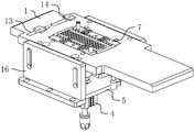
FIG. 1 is a schematic view of the overall structure of the positioning structure;
FIG. 2 is an exploded view primarily intended to illustrate the mold mounting structure;
FIG. 3 is a side view of the positioning structure;
FIG. 4 is a schematic view of a jacking platform and a positioning thimble;
fig. 5 is a schematic structural view mainly used for detaching and connecting the positioning thimble to the jacking platform.
Reference numerals: 1. a work table; 11. positioning a groove; 12. mounting grooves; 2. jacking a platform; 21. an adjustment groove; 22. an adjusting block; 3. positioning the thimble; 4. a drive assembly; 5. a fixing plate; 61. a linear bearing; 62. a guide post; 7. a mold; 8. a limiting block; 81. a kidney-shaped hole; 101. a vacuum adsorption box; 102. a vacuum adsorption tube; 103. an adsorption hole; 13. a fixing groove; 14. a moving block; 15. connecting columns; 16. a support plate; 100. a negative film; 200. and (4) a small hole.
Detailed Description
The present application is described in further detail below with reference to figures 1-5.
Referring to fig. 1, a sheet material accurate alignment structure for a pasting machine is disclosed in an embodiment of the present application. This kind of a sheet accurate counterpoint structure for pasting machine includes fixed plate 5 that the level set up, at the vertical backup pad 16 that is equipped with in 5 length direction both sides of fixed plate, fixedly connected with workstation 1 between two backup pads 16, wherein 1 upper surface of workstation is used for film 100 to pass through.
Referring to fig. 1 and 2, a rectangular mounting groove 12 is formed on the surface of the table 1, a die 7 is bolted in the mounting groove 12, the length direction of the die 7 is parallel to the length direction of the fixing plate 5, and the base sheet 100 stays on the surface of the die 7 when the base sheet is attached to the fixing plate. Positioning grooves 11 are formed in two sides of the length direction of the upper surface of the mold 7, and the length direction of the positioning grooves 11 is parallel to the length direction of the mold 7; the surface of the mold 7 is also provided with limiting blocks 8 along the two sides of the length direction of the mold, the bottom surfaces of the limiting blocks 8 are attached to the surface of the bottom sheet 100, in order to limit the bottom sheet 100 in the vertical direction, waist-shaped holes 81 are formed in the limiting blocks 8 in order to adapt to products with different widths, the length direction of the waist-shaped holes 81 is perpendicular to the feeding direction of the bottom sheet 100, and the waist-shaped holes are connected to the mold 7 through bolts.
Referring to fig. 2, fixed slot 13 has all been seted up at workstation 1 length direction's both ends, slides in fixed slot 13 and is equipped with two movable blocks 14, and movable block 14 is in fixed slot 13 through bolted connection equally, and the loosening bolt can drive movable block 14 and remove to adjust the distance between two movable blocks 14, two relative one sides of movable block 14 and film 100 butt, with the spacing of adaptation different width products, guarantee the accuracy of product operation in-process.
Referring to fig. 3, 4 and 5, a jacking platform 2 is horizontally arranged above a fixing plate 5, four positioning thimbles 3 are vertically arranged on the jacking platform 2, the four positioning thimbles 3 are arranged in a rectangular shape, the axis of each positioning thimble 3 passes through the central line of the length direction of a positioning groove 11, and when the positioning thimbles 3 are inserted into the positioning grooves 11, the outer side walls of the positioning thimbles 3 are attached to the inner side walls of the small holes 200; be equipped with the drive assembly 4 that is used for driving 2 lifts of jacking platform on fixed plate 5, drive assembly 4 includes the vertical fixed telescopic cylinder that sets up in fixed plate 5 bottom surfaces in this embodiment, and telescopic cylinder's piston rod is vertical to run through the setting of fixed plate 5, and telescopic cylinder's piston rod tip fixed connection is in jacking platform 2's bottom surface. When the bottom plate 100 is positioned, the bottom plate 100 moves to a position corresponding to the mold 7, so that the small hole 200 is coaxial with the positioning thimble 3, the driving assembly 4 is started to drive the jacking platform 2 and the positioning thimble 3 to move upwards, and the positioning thimble 3 finally penetrates into the small hole 200 through the positioning groove 11, so that the positioning can be completed.
Referring to fig. 2 and 4, the bottom surface of the mounting groove 12 and the die 7 are both provided with an adsorption hole 103, the bottom surface of the workbench 1 is provided with a vacuum adsorption box 101, the vacuum adsorption box 101 is externally connected with a vacuum adsorption tube 102, and when the positioning ejector pin 3 fixes the base sheet 100, the vacuum adsorption box 101 is started to further adsorb and fix the base sheet 100, so that the accuracy of fixing the position of the base sheet 100 is further ensured, and the pasting quality is improved.
Referring to fig. 3 and 4, vertically between workstation 1 and fixed plate 5 be equipped with many spliced poles 15 for guarantee the stability of workstation 1, vertically on fixed plate 5 be equipped with linear bearing 61, the vertical guide post 62 that is equipped with in workstation 1 bottom surface, guide post 62 and linear bearing 61 alternate the setting, thereby guarantee the stability and the accuracy of jacking platform 2 motion.
Referring to 5, an adjusting groove 21 is formed in the jacking platform 2 in the length direction of the parallel fixing plate 5, an adjusting block 22 is arranged below the positioning ejector pin 3, an adjusting screw penetrates through the adjusting groove 21 and the adjusting block 22, and the position of the positioning ejector pin 3 can be adjusted along the length direction of the adjusting groove 21 due to the setting, so that the film 100 with different hole pitches can be adapted, and the adaptability is high.
The implementation principle of the sheet accurate alignment structure for the attaching machine is as follows: when the film 100 moves to the corresponding position of the workbench 1, the axis of the small hole 200 passes through the central line of the positioning groove 11, the driving assembly 4 is started at the moment, the positioning thimbles 3 are driven to simultaneously penetrate through the positioning groove 11 and the small hole 200, the outer side wall of the positioning thimbles 3 just corresponds to the inner side wall of the fitting small hole 200, the positioning thimbles 3 penetrate through the small holes 200, so that the position of the film 100 is firmly fixed, meanwhile, the vacuum adsorption tube 102, the vacuum adsorption hole 103 and the vacuum adsorption box 101 are utilized to further adsorb and fix a product, the accuracy of the position of the film 100 is ensured, and finally, the top film is fitted downwards, so that the displacement error of the film 100 is effectively reduced, and the fitting accuracy is improved.
The above embodiments are preferred embodiments of the present application, and the protection scope of the present application is not limited by the above embodiments, so: all equivalent changes made according to the structure, shape and principle of the present application shall be covered by the protection scope of the present application.
Claims (8)
1. The utility model provides a sheet accurate counterpoint structure for to machine of pasting which characterized in that includes:
the device comprises a workbench (1), wherein a positioning groove (11) matched with the small hole is formed in the workbench (1);
the jacking platform (2) is arranged below the workbench (1), a plurality of positioning thimbles (3) are vertically arranged on the surface of the jacking platform (2), positioning grooves (11) are vertically inserted into the positioning thimbles (3), and the outer side walls of the positioning thimbles (3) are attached to the inner side walls of the small holes;
the driving component (4), the driving component (4) is used for driving the jacking platform (2) to lift.
2. The sheet material accurate alignment structure for the pasting machine as claimed in claim 1, wherein: the fixed plate (5) that is equipped with of bottom surface level of workstation (1), vertically on fixed plate (5) be equipped with linear bearing (61), workstation (1) bottom surface is vertical to be equipped with guide post (62), guide post (62) alternate the setting with linear bearing (61).
3. The sheet material accurate alignment structure for the pasting machine as claimed in claim 1, wherein: workstation (1) top surface is equipped with mounting groove (12), the dismantlement is equipped with mould (7) in mounting groove (12), location thimble (3) are dismantled and are set up on jacking platform (2).
4. The accurate sheet aligning structure for a laminating machine according to claim 3, wherein: mould (7) bolted connection is in mounting groove (12), regulation groove (21) have been seted up along film direction of transportation on jacking platform (2), location thimble (3) below is equipped with regulating block (22), runs through regulating groove (21) and regulating block (22) simultaneously and is equipped with adjusting screw.
5. The sheet material accurate alignment structure for the pasting machine as claimed in claim 3, wherein: the length direction of the length direction parallel mounting groove (12) of mould (7), mould (7) surface all is equipped with stopper (8) along self length direction's both sides, the bottom surface and the laminating of film surface of stopper (8).
6. The sheet material accurate alignment structure for the pasting machine as claimed in claim 5, wherein: every waist type hole (81) have all been seted up on stopper (8), the length direction of the perpendicular mould of length direction (7) in waist type hole (81), the vertical bolt that is used for fixed stopper (8) position that is equipped with in waist type hole (81).
7. The sheet material accurate alignment structure for the pasting machine as claimed in claim 3, wherein: mould (7) bottom surface is equipped with vacuum adsorption box (101), vacuum adsorption box (101) are external to have vacuum adsorption pipe (102), adsorption hole (103) have all been opened corresponding vacuum adsorption box (101) on workstation (1) and mould (7).
8. The sheet material accurate alignment structure for the pasting machine as claimed in claim 1, wherein: fixed grooves (13) are formed in two ends of the workbench (1) in the length direction, two moving blocks (14) are arranged in the fixed grooves (13) in a sliding mode, and one surfaces, opposite to the two moving blocks (14), are abutted to the bottom plate.
Priority Applications (1)
| Application Number | Priority Date | Filing Date | Title |
|---|---|---|---|
| CN202220430061.1U CN217455272U (en) | 2022-02-28 | 2022-02-28 | Sheet accurate alignment structure for opposite pasting machine |
Applications Claiming Priority (1)
| Application Number | Priority Date | Filing Date | Title |
|---|---|---|---|
| CN202220430061.1U CN217455272U (en) | 2022-02-28 | 2022-02-28 | Sheet accurate alignment structure for opposite pasting machine |
Publications (1)
| Publication Number | Publication Date |
|---|---|
| CN217455272U true CN217455272U (en) | 2022-09-20 |
Family
ID=83266629
Family Applications (1)
| Application Number | Title | Priority Date | Filing Date |
|---|---|---|---|
| CN202220430061.1U Active CN217455272U (en) | 2022-02-28 | 2022-02-28 | Sheet accurate alignment structure for opposite pasting machine |
Country Status (1)
| Country | Link |
|---|---|
| CN (1) | CN217455272U (en) |
-
2022
- 2022-02-28 CN CN202220430061.1U patent/CN217455272U/en active Active
Similar Documents
| Publication | Publication Date | Title |
|---|---|---|
| CN204639554U (en) | A kind of automatic aligning laminating mechanism | |
| CN104858637A (en) | Automatic alignment press-fit mechanism | |
| CN201353803Y (en) | Device for positioning and clamping sheet material of multi-blade saw machine | |
| WO2012100725A1 (en) | Light gantry numerical control cutting machine | |
| CN217455272U (en) | Sheet accurate alignment structure for opposite pasting machine | |
| CN105562950B (en) | Pressure vessel fixture for laser welding and the method that laser welding is carried out using the fixture | |
| CN211971025U (en) | Vision positioning conveyor | |
| CN210296519U (en) | Hydraulic press for assembling fuel cell stack | |
| CN210415499U (en) | Carrier tape forming device | |
| CN210969255U (en) | Adjustable wood board feeding device | |
| CN110366332B (en) | Translational type hot melting machine aligned by camera | |
| CN210550603U (en) | Electricity core tool | |
| CN210908851U (en) | Battery piece pressure equipment device | |
| CN113369847A (en) | Automatic nut assembling mechanism | |
| CN208012221U (en) | A kind of door body automatic clamping device | |
| CN109262174B (en) | Three-dimensional one-stop type elevator derrick manufacturing tool platform | |
| CN218926380U (en) | Building board cutting device with guiding mechanism | |
| CN215515656U (en) | Width-adjustable material supporting and feeding mechanism | |
| CN110315204A (en) | Double-station list laser lens multistage welding equipment | |
| CN218140197U (en) | Packing box facial tissue packagine machine constructs | |
| CN220005477U (en) | Straight rail straightener | |
| CN220429422U (en) | Equidistant cutting equipment for carton processing | |
| CN110434937A (en) | A kind of edge banding machine upper and lower surface and groove at side surface device | |
| CN220885850U (en) | Panel loading attachment | |
| CN218691036U (en) | Single-head fine-adjustment needle cylinder jig |
Legal Events
| Date | Code | Title | Description |
|---|---|---|---|
| GR01 | Patent grant | ||
| GR01 | Patent grant |