CN217451235U - Circuit board immersion cleaning device - Google Patents
Circuit board immersion cleaning device Download PDFInfo
- Publication number
- CN217451235U CN217451235U CN202221355673.5U CN202221355673U CN217451235U CN 217451235 U CN217451235 U CN 217451235U CN 202221355673 U CN202221355673 U CN 202221355673U CN 217451235 U CN217451235 U CN 217451235U
- Authority
- CN
- China
- Prior art keywords
- pipe
- circuit board
- vertical plates
- case
- chemical cleaning
- Prior art date
- Legal status (The legal status is an assumption and is not a legal conclusion. Google has not performed a legal analysis and makes no representation as to the accuracy of the status listed.)
- Active
Links
Images


Classifications
-
- Y—GENERAL TAGGING OF NEW TECHNOLOGICAL DEVELOPMENTS; GENERAL TAGGING OF CROSS-SECTIONAL TECHNOLOGIES SPANNING OVER SEVERAL SECTIONS OF THE IPC; TECHNICAL SUBJECTS COVERED BY FORMER USPC CROSS-REFERENCE ART COLLECTIONS [XRACs] AND DIGESTS
- Y02—TECHNOLOGIES OR APPLICATIONS FOR MITIGATION OR ADAPTATION AGAINST CLIMATE CHANGE
- Y02W—CLIMATE CHANGE MITIGATION TECHNOLOGIES RELATED TO WASTEWATER TREATMENT OR WASTE MANAGEMENT
- Y02W30/00—Technologies for solid waste management
- Y02W30/50—Reuse, recycling or recovery technologies
- Y02W30/82—Recycling of waste of electrical or electronic equipment [WEEE]
Landscapes
- Manufacturing Of Printed Wiring (AREA)
Abstract
The utility model discloses a circuit board immersion cleaning device, which comprises a case, wherein a conveyor belt is arranged in the case, three groups of vertical plates are arranged at the top ends of the two sides of the case, a drainage step is arranged at the bottom in the case, a drain pipe is arranged at the bottom of one end of the case, an infiltration pipe, a chemical cleaning pipe and a spray pipe are respectively arranged on the vertical plates, the vertical plates are symmetrically and fixedly arranged at the top of the case, and through the arranged rack plates and a driving motor, when the conveying belt drives the circuit board to pass through the bottom of the chemical cleaning pipe, the driving motor drives the rack plate to reciprocate left and right through the gear B, the top of the rack plate is meshed and connected with the gear A on the connector, therefore, the rack plate can simultaneously drive the chemical cleaning pipe to rotate left and right in a reciprocating manner, the spray head can spray chemical cleaning substances to the circuit board at different angles, and compared with the traditional spray head in a fixed vertical direction, the cleaning degree of the circuit board can be improved by the aid of the mode.
Description
Technical Field
The utility model relates to a circuit board washs technical field, specifically is a circuit board soaks and washes device.
Background
During the processing of the circuit board, things such as soldering flux and the like are used, particularly repaired boards, some foreign matters such as fingerprints, sweat stains, rosin in gaps, the soldering flux and the like are left by manual welding, and the remaining matters can adsorb oil stains, dust and the like, so that adverse effects and consequences are caused on the work of the circuit board.
The existing chemical immersion cleaning mode is adopted, the circuit board is generally conveyed at intervals through a conveying belt, the steps of chemical infiltration, chemical cleaning, spraying, wind cutting, drying and the like are sequentially carried out when the circuit board passes through a case, and the steps of spraying chemical substances are generally carried out through a spray head before the traditional device, but because the spray head is fixed and cannot be obliquely adjusted, the chemical substances cannot be well sprayed on the circuit board to achieve a better cleaning effect.
Accordingly, one skilled in the art provides a circuit board soaking device to solve the above problems in the background art.
SUMMERY OF THE UTILITY MODEL
An object of the utility model is to provide a circuit board soaks device to solve the problem that proposes among the above-mentioned background art.
In order to achieve the above object, the utility model provides a following technical scheme:
the utility model provides a circuit board immersion cleaning device, includes quick-witted case, the internally mounted of quick-witted case has the conveyer belt, and three group's risers are installed on the both sides top of quick-witted case, and the bottom is provided with the drainage step in the quick-witted case, and the one end bottom of quick-witted case link up and is provided with the drain pipe, is provided with infiltration pipe, chemical cleaning tube, shower on the riser respectively.
As the utility model discloses scheme further again, the riser is located the fixed setting of quick-witted roof portion symmetry, and riser fixed mounting has the dead lever between two liang, and the bottom equidistance of infiltration pipe, chemical cleaning tube, shower link up and is provided with the shower nozzle.
As the utility model discloses scheme further again, the chemistry scavenge pipe is located and rotates the installation between two liang of risers, and riser and fixedly connected with connector are run through to the one end of chemistry scavenge pipe, and the one end fixed mounting of connector has gear A.
As the utility model discloses further scheme, three groups wherein lie in the fixed locating lever that is provided with in one side of installation chemical cleaning tube riser on the riser, install the rack board on the locating lever.
As the utility model discloses further scheme again, spacing through-hole has been seted up to the both ends symmetry of rack board, and movable mounting about rack board inserts spacing through-hole through the locating lever and forms, and the one end of locating lever is provided with limit structure.
As the utility model discloses scheme further again, the one end bottom of rack plate is provided with the drive rack, and top one side fixed mounting of machine case has driving motor, and driving motor's output shaft fixed mounting has gear B, and gear B is connected with the drive rack meshing, and the top and the gear A meshing of rack plate are connected.
As a further proposal of the utility model, the top of the case is positioned between the infiltration pipe, the chemical cleaning pipe and the spray pipe and is fixedly provided with a clapboard.
Compared with the prior art, the beneficial effects of the utility model are that:
1. through the rack board that sets up, driving motor, when the conveyer belt drives the circuit board through chemical cleaning tube bottom portion, driving motor passes through gear B and drives reciprocating motion about the rack board, and the meshing of gear A on rack board top and the connector is connected, and reciprocating rotation about consequently the rack board can drive chemical cleaning tube simultaneously realizes that the shower nozzle can spray chemical cleaning material to the different angles of circuit board, and the fixed vertical direction of more traditional shower nozzle sprays and compares, and this mode can improve the clean degree of circuit board.
2. Through the arranged drainage steps, the liquid sprayed after cleaning and chemically cleaned can sequentially flow into the lowest drainage step and is discharged through the drainage pipe, so that the liquid after cleaning is conveniently and intensively treated.
Drawings
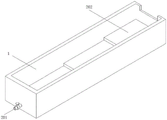
FIG. 1 is a schematic view of the overall structure of a circuit board immersion cleaning apparatus;
FIG. 2 is a schematic view of the interior of a circuit board soaking device;
fig. 3 is an enlarged view of a circuit board soaking device at a.
In the figure: 1. a chassis; 101. fixing the rod; 102. a vertical plate; 103. a partition plate; 104. infiltrating a pipe; 105. a chemical purge tube; 106. a spray head; 107. a conveyor belt; 108. a shower pipe; 2. a connector; 201. a drain pipe; 202. a drainage step; 203. a rack plate; 204. a gear A; 205. positioning a rod; 206. a drive motor; 207. a gear B; 208. a drive rack; 209. and limiting through holes.
Detailed Description
Please refer to fig. 1-3, in the embodiment of the present invention, a circuit board immersion cleaning device, including the machine case 1, the internally mounted of machine case 1 has the conveyer belt 107, three sets of risers 102 are installed on the both sides top of machine case 1, the bottom is provided with drainage step 202 in the machine case 1, the one end bottom of machine case 1 link up and is provided with drain pipe 201, be provided with infiltration pipe 104 on the riser 102 respectively, chemical cleaning tube 105, shower 108, riser 102 is located the fixed setting of machine case 1 top symmetry, and fixed mounting has dead lever 101 between two liang of riser 102, increase the installation stability, infiltration pipe 104, chemical cleaning tube 105, the bottom equidistance of shower 108 link up and is provided with shower nozzle 106, wherein be located the fixed locating lever 205 that is provided with in one side of installation chemical cleaning tube 105 riser 102 on three sets of risers 102, install rack plate 203 on the locating lever 205.
As shown in fig. 1-3, the chemical cleaning tube 105 is rotatably installed between two vertical plates 102, one end of the chemical cleaning tube 105 penetrates through the vertical plates 102 and is fixedly connected with the connector 2, and one end of the connector 2 is fixedly installed with a gear a204, which is convenient for driving the connector 2 and the chemical cleaning tube 105 to rotate.
As shown in fig. 1-3, the two ends of the rack plate 203 are symmetrically provided with limiting through holes 209, the rack plate 203 is movably installed in the left and right direction by inserting the positioning rod 205 into the limiting through holes 209, and one end of the positioning rod 205 is provided with a limiting structure to prevent the rack plate 203 from falling off when moving.
As shown in fig. 1 to fig. 3, a driving rack 208 is disposed at the bottom of one end of the rack plate 203, a driving motor 206 is fixedly mounted at one side of the top of the cabinet 1, a gear B207 is fixedly mounted on an output shaft of the driving motor 206, the gear B207 is engaged with the driving rack 208, and the top end of the rack plate 203 is engaged with the gear a204, so that the driving motor 206 can drive the chemical cleaning pipe 105 to rotate back and forth.
As shown in fig. 1-3, a partition plate 103 is fixedly installed on the top of the cabinet 1 between the immersion pipe 104, the chemical cleaning pipe 105 and the spray pipe 108, and the height of the drainage step 202 is reduced toward one end of the drainage pipe 201 in sequence, so as to facilitate the liquid discharge and centralized treatment after cleaning.
The utility model discloses a theory of operation is: when the machine works, the circuit boards are placed on the conveyor belt 107 in the case 1 one by one, firstly, the wetting pipe 104 sprays wetted chemical substances to the circuit boards, when the circuit boards are conveyed to the bottom of the chemical cleaning pipe 105 through the conveyor belt 107, the chemical cleaning pipe 105 sprays the chemical cleaning substances to the circuit boards again, meanwhile, the driving motor 206 is meshed with the driving rack 208 through the gear B207, the top of the rack plate 203 is meshed with the gear A204 on the connector 2, therefore, when the driving motor 206 rotates, the rack plate 203 can simultaneously drive the chemical cleaning pipe 105 to reciprocate left and right, the purpose that the spray head 106 can spray the chemical cleaning substances to the circuit boards at different angles is realized, compared with the traditional spray head 106 which fixes the spray in the vertical direction, the mode can improve the cleaning degree of the circuit boards, the height of the drainage step 202 is sequentially reduced towards one end of the drainage pipe 201, the liquid after cleaning is conveniently discharged and concentrated, and finally, after the circuit boards are cleaned through the spray pipe 108, and feeding into a lower air drying device.
The above-mentioned, only be the concrete implementation of the preferred embodiment of the present invention, but the protection scope of the present invention is not limited thereto, and any person skilled in the art is in the technical scope of the present invention, according to the technical solution of the present invention and the utility model, the concept of which is equivalent to replace or change, should be covered within the protection scope of the present invention.
Claims (7)
1. The utility model provides a circuit board soaks device, includes quick-witted case (1), its characterized in that: the automatic cleaning machine is characterized in that a conveyor belt (107) is arranged inside the machine case (1), three groups of vertical plates (102) are arranged at the top ends of the two sides of the machine case (1), a drainage step (202) is arranged at the bottom in the machine case (1), a drainage pipe (201) is arranged at the bottom of one end of the machine case (1) in a penetrating mode, and a soaking pipe (104), a chemical cleaning pipe (105) and a spraying pipe (108) are arranged on the vertical plates (102) respectively.
2. The circuit board immersion cleaning device according to claim 1, wherein the vertical plates (102) are symmetrically and fixedly arranged on the top of the cabinet (1), fixing rods (101) are fixedly arranged between every two vertical plates (102), and spray heads (106) are arranged at the bottoms of the soaking pipe (104), the chemical cleaning pipe (105) and the spray pipe (108) in a penetrating manner at equal intervals.
3. The circuit board immersion cleaning device according to claim 1, wherein the chemical cleaning tube (105) is rotatably mounted between every two vertical plates (102), one end of the chemical cleaning tube (105) penetrates through the vertical plates (102) and is fixedly connected with the connector (2), and one end of the connector (2) is fixedly provided with a gear A (204).
4. The circuit board immersion cleaning device according to claim 1, wherein a positioning rod (205) is fixedly arranged on one side of the three groups of vertical plates (102) where the vertical plates (102) of the chemical cleaning pipe (105) are arranged, and a rack plate (203) is arranged on the positioning rod (205).
5. The device for soaking and washing the circuit board according to claim 4, characterized in that the two ends of the rack plate (203) are symmetrically provided with limiting through holes (209), the rack plate (203) is movably installed left and right by inserting the positioning rod (205) into the limiting through holes (209), and one end of the positioning rod (205) is provided with a limiting structure.
6. The circuit board immersion cleaning device according to claim 5, wherein a driving rack (208) is arranged at the bottom of one end of the rack plate (203), a driving motor (206) is fixedly installed at one side of the top of the case (1), a gear B (207) is fixedly installed at an output shaft of the driving motor (206), the gear B (207) is meshed with the driving rack (208), and the top end of the rack plate (203) is meshed with the gear A (204).
7. The circuit board immersion cleaning device according to claim 1, wherein a partition plate (103) is fixedly installed at the top of the case (1) among the immersion pipe (104), the chemical cleaning pipe (105) and the spray pipe (108), and the height of the drainage step (202) is sequentially reduced toward one end of the drainage pipe (201).
Priority Applications (1)
| Application Number | Priority Date | Filing Date | Title |
|---|---|---|---|
| CN202221355673.5U CN217451235U (en) | 2022-06-01 | 2022-06-01 | Circuit board immersion cleaning device |
Applications Claiming Priority (1)
| Application Number | Priority Date | Filing Date | Title |
|---|---|---|---|
| CN202221355673.5U CN217451235U (en) | 2022-06-01 | 2022-06-01 | Circuit board immersion cleaning device |
Publications (1)
| Publication Number | Publication Date |
|---|---|
| CN217451235U true CN217451235U (en) | 2022-09-20 |
Family
ID=83276926
Family Applications (1)
| Application Number | Title | Priority Date | Filing Date |
|---|---|---|---|
| CN202221355673.5U Active CN217451235U (en) | 2022-06-01 | 2022-06-01 | Circuit board immersion cleaning device |
Country Status (1)
| Country | Link |
|---|---|
| CN (1) | CN217451235U (en) |
-
2022
- 2022-06-01 CN CN202221355673.5U patent/CN217451235U/en active Active
Similar Documents
| Publication | Publication Date | Title |
|---|---|---|
| CN111394764B (en) | Electrogalvanizing production line for roller and production process thereof | |
| CN113964064B (en) | Etching equipment for producing integrated circuit lead frame | |
| CN211247510U (en) | Spray cleaning module and through type spray cleaning machine | |
| CN102896110A (en) | Steel net washing machine and washing method | |
| CN217451235U (en) | Circuit board immersion cleaning device | |
| CN111011890A (en) | Fountain brush apple cleaning machine | |
| CN210546650U (en) | Horizontal electroplating line circulation water saving fixtures of PCB board | |
| CN114828419A (en) | Processing equipment and process for multi-azimuth adjustment and movement of plated hole of blind hole of HDI circuit board | |
| CN213468916U (en) | Dust collector is used in processing of PCB board | |
| CN209861299U (en) | Circuit board surface treatment device | |
| CN211557653U (en) | PCB surface cleaning device | |
| CN110791786B (en) | Electroplating solution adding and spraying device for electroplating PCB | |
| CN217911852U (en) | Automatic cleaning equipment for printed circuit board | |
| CN111618005A (en) | Cleaning device for electroplating processing of circuit board and using method thereof | |
| CN113477586A (en) | Cleaning equipment with automatic feeding and discharging structure and cleaning method thereof | |
| CN214046195U (en) | Acid dip pickle is used in PCB production | |
| CN218282835U (en) | Surface cleaning device for marble processing | |
| CN214960347U (en) | Cleaning equipment for printed circuit board | |
| CN219523392U (en) | Screen plate cleaning device | |
| CN218735270U (en) | Tin stripping water circulation working device | |
| CN205160935U (en) | PCB board self - cleaning device | |
| CN216064413U (en) | Brushing device of multilayer circuit board processing for communication equipment | |
| CN217973481U (en) | Wash even PCB board gilding washing tank | |
| CN219309471U (en) | PCB board clearance drying device | |
| CN214254363U (en) | Semiconductor wafer cleaning device |
Legal Events
| Date | Code | Title | Description |
|---|---|---|---|
| GR01 | Patent grant | ||
| GR01 | Patent grant |