CN217366422U - Upper limb lifting frame convenient to adjust for orthopedic surgery - Google Patents
Upper limb lifting frame convenient to adjust for orthopedic surgery Download PDFInfo
- Publication number
- CN217366422U CN217366422U CN202123119257.3U CN202123119257U CN217366422U CN 217366422 U CN217366422 U CN 217366422U CN 202123119257 U CN202123119257 U CN 202123119257U CN 217366422 U CN217366422 U CN 217366422U
- Authority
- CN
- China
- Prior art keywords
- fixed
- rod
- sliding block
- side wall
- sliding
- Prior art date
- Legal status (The legal status is an assumption and is not a legal conclusion. Google has not performed a legal analysis and makes no representation as to the accuracy of the status listed.)
- Active
Links
Images


Abstract
An upper limb lifting frame for orthopedic surgery convenient to adjust relates to the technical field of medical instruments, a first motor is fixed on the right side wall of a second fixed rod on the left side, and the first motor is connected with an external power supply; the left end of the screw rod is fixed with an output shaft of the first motor, and the right end of the screw rod is screwed on the left side wall of the second fixing rod on the right side through a bearing; the screw nut is screwed and sleeved on the screw rod; the left end and the right end of the first sliding rod are respectively fixed on the inner side walls of the left fixing rod and the right fixing rod; the position can be adjusted up, down, left and right according to the needs of the patient, so that the upper limb of the patient can be conveniently placed, the stability is higher, and the practicability is improved; the patient is prevented from being directly suspended by the binding rope to cause necrosis, the safety is improved, and the patient feels more comfortable.
Description
Technical Field
The utility model relates to the technical field of medical equipment, concretely relates to frame is raised to orthopedic surgery with upper limbs convenient to adjust.
Background
Orthopedics is one of the most common departments in all hospitals, and mainly studies the anatomy, physiology and pathology of the skeletal muscle system, and maintains and develops the normal form and function of the system by using medicines, operations and physical methods.
Traditional bone surgery fixing device can not adjust the position about patient's needs about fixed upper limbs on the existing market, and simply utilizes the rope to fix and suspend in midair, and is not only unstable, still causes the necrosis easily.
SUMMERY OF THE UTILITY MODEL
The utility model aims to provide an upper limb lifting frame for orthopedic surgery, which is convenient to adjust, aiming at the defects and shortcomings of the prior art, can adjust the position up, down, left and right according to the needs of a patient, is convenient to place the upper limb of the patient, is more stable and improves the practicability; the patient is prevented from being directly suspended by the binding rope to cause necrosis, the safety is improved, and the patient feels more comfortable.
In order to achieve the above object, the utility model adopts the following technical scheme: the universal wheel comprises a first fixed rod, a second fixed rod, a base and a universal wheel; a second fixing rod is fixed at the left end and the right end of the lower surface of the first fixing rod; the bottoms of the left and right second fixing rods are fixed on the base; four corners of the bottom of the base are respectively and rotatably connected with universal wheels through shafts and bearings;
it also includes:
the first motor is fixed on the right side wall of the second fixing rod on the left side and is connected with an external power supply;
the left end of the screw rod is fixed with an output shaft of the first motor, and the right end of the screw rod is screwed on the left side wall of the second fixing rod on the right side through a bearing;
the screw nut is sleeved on the screw rod in a screwing manner;
the left end and the right end of the first sliding rod are respectively fixed on the inner side walls of the left fixing rod and the right fixing rod; the first sliding rod is arranged below the screw rod;
the first sliding block is arranged on the first sliding rod in a sliding manner;
the second sliding rod is fixed on the first sliding block, and the upper end of the second sliding rod is fixed at the lower end of the screw;
the second sliding block is arranged on the second sliding rod in a sliding manner;
the rear end of the first supporting rod is fixed on the front side wall of the second sliding block;
the fixed end of the first electric telescopic rod is fixed on the front side of the upper surface of the first sliding block, and the first electric telescopic rod is connected with an external power supply; the movable end of the first electric telescopic rod is fixed with the lower end of the first supporting rod;
the arc-shaped plate is fixed on the first supporting rod;
the number of the binding bands is two, and the rear ends of the binding bands are fixed at the upper end of the rear side of the arc-shaped plate;
the third sliding block is arranged on the second fixing rod on the right side in a sliding mode;
the fixed end of the second electric telescopic rod is fixed on the right front side of the upper surface of the base, and the second electric telescopic rod is connected with an external power supply; the movable end of the second electric telescopic rod is fixed with the front side of the lower surface of the third sliding block;
the rear end of the screw is screwed at the upper end of the front side wall of the third sliding block through a bearing;
the internal thread pipe is movably sleeved at the front part of the screw rod through threads;
the spring is arranged in the internal thread pipe, the rear end of the spring is fixed at the front end of the screw rod, and the front end of the spring is fixed on the inner side wall of the internal thread pipe;
the rear end of the first connecting rod is fixed at the upper end of the front side wall of the internal thread pipe;
the connecting shaft is inserted and fixed at the front end of the first connecting rod;
the number of the second connecting rods is two, and the left and right second connecting rods are respectively connected with the left and right ends of the connecting shaft in a rotating manner through bearings;
the rear side wall of the supporting plate is fixed with the two second connecting rods;
the back cushion is fixed on the front side wall of the supporting plate.
Preferably, a sponge cushion is fixed on the inner annular wall of the arc-shaped plate.
Preferably, a second supporting rod is fixed on the rear side wall of the lower portion of the second fixing rod, and a rubber pad is fixed at the lower end of the second supporting rod.
Preferably, the lower end of the internal threaded pipe is fixed with a limiting rod which is arranged in an L-shaped structure; a limiting pipe is fixed at the lower end of the front side wall of the third sliding block, and the rear end of a cross rod of the limiting rod is movably inserted in the limiting pipe; a second motor is fixed on the front side of the upper end of the third sliding block and connected with an external power supply; the output shaft of the second motor is rotatably connected with a first gear through a shaft and a coupler; a second gear is fixedly sleeved at the rear end of the screw; no. two gears are arranged below the first gear, and the first gear and the second gear are arranged in a meshed mode.
Compared with the prior art, the beneficial effects of the utility model are that: the utility model provides an upper limb lifting frame for orthopedic surgery, which can adjust the position up, down, left and right according to the needs of the patient, is convenient for placing the upper limb of the patient, is more stable and improves the practicability; the patient is prevented from being directly suspended by the binding rope to cause necrosis, the safety is improved, and the patient feels more comfortable.
Drawings
In order to more clearly illustrate the embodiments of the present invention or the technical solutions in the prior art, the drawings needed to be used in the description of the embodiments or the prior art will be briefly described below, it is obvious that the drawings in the following description are only some embodiments of the present invention, and for those skilled in the art, other drawings can be obtained according to these drawings without inventive exercise.
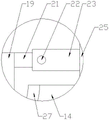
Fig. 1 is a schematic structural diagram of the present invention.
Fig. 2 is a sectional view taken along line a-a in fig. 1.
Fig. 3 is an enlarged view of a portion C in fig. 2.
Fig. 4 is an enlarged view of a portion D in fig. 2.
Fig. 5 is a sectional view taken along line B-B in fig. 1.
Fig. 6 is an enlarged view of a portion E in fig. 5.
Fig. 7 is a left side view of fig. 1.
Fig. 8 is an enlarged view of a portion F in fig. 7.
Description of reference numerals:
no. one dead lever 1, No. two dead levers 2, base 3, universal wheel 4, No. one motor 5, lead screw 6, screw 7, slide bar 8, slider 9, No. two slide bars 10, No. two slider 11, bracing piece 12, electric telescopic handle 13, arc 14, bandage 15, No. three slider 16, No. two electric telescopic handle 17, screw rod 18, internal thread pipe 19, spring 20, connecting rod 21, connecting axle 22, No. two connecting rod 23, backup pad 24, cushion 25, foam-rubber cushion 27, No. two bracing piece 28, rubber pad 29, gag lever post 30, spacing pipe 31, No. two motors 32, No. one gear 33, No. two gears 34.
Detailed Description
The present invention will be further described with reference to the accompanying drawings.
Referring to fig. 1 to 8, the technical solution adopted by the present embodiment is: the device comprises a first fixed rod 1, a second fixed rod 2, a base 3 and a universal wheel 4; the left end and the right end of the lower surface of the first fixing rod 1 are both fixed with a second fixing rod 2 through bolts; the bottoms of the left and right second fixing rods 2 are fixed on the base 3 through bolts; four corners of the bottom of the base 3 are respectively and rotatably connected with universal wheels 4 through shafts and bearings;
it also includes:
the first motor 5 is fixed on the right side wall of the second fixing rod 2 on the left side through a bolt, and the first motor 5 is connected with an external power supply;
the left end of the screw rod 6 is fixed with an output shaft of the first motor 5 through a bolt, and the right end of the screw rod 6 is screwed on the left side wall of the second fixing rod 2 on the right side through a bearing;
the screw 7 is sleeved on the screw rod 6 in a screwing way;
the left end and the right end of the first sliding rod 8 are respectively fixed on the inner side walls of the left fixing rod 2 and the right fixing rod 2 through bolts; the first sliding rod 8 is arranged below the screw rod 6;
the first sliding block 9 is arranged on the first sliding rod 8 in a sliding manner;
the second sliding rod 10 is fixedly welded on the first sliding block 9, and the upper end of the second sliding rod 10 is fixed at the lower end of the screw 7 through a bolt;
the second sliding block 11 is arranged on the second sliding rod 10 in a sliding manner;
the rear end of the first supporting rod 12 is fixed on the front side wall of the second sliding block 11 through a bolt;
the fixed end of the first electric telescopic rod 13 is fixed on the front side of the upper surface of the first sliding block 9 through a bolt, and the first electric telescopic rod 13 is connected with an external power supply; the movable end of the first electric telescopic rod 13 is fixed with the lower end of the first support rod 12 through a bolt;
the arc-shaped plate 14 is fixed on the first support rod 12 through bolts;
the number of the binding bands 15 is two, and the rear ends of the binding bands 15 are fixed at the upper ends of the rear sides of the arc-shaped plates 14 through bolts;
the third sliding block 16 is arranged on the second fixing rod 2 on the right side in a sliding manner;
the fixed end of the second electric telescopic rod 17 is fixed on the right front side of the upper surface of the base 3 through a bolt, and the second electric telescopic rod 17 is connected with an external power supply; the movable end of the second electric telescopic rod 17 is fixed with the front side of the lower surface of the third sliding block 16 through a bolt;
the rear end of the screw rod 18 is screwed at the upper end of the front side wall of the third sliding block 16 through a bearing;
the internal threaded pipe 19 is movably sleeved at the front part of the screw rod 18 through threads;
the spring 20 is arranged in the internally threaded pipe 19, the rear end of the spring 20 is fixed at the front end of the screw 18 through a bolt, and the front end of the spring 20 is fixed on the inner side wall of the internally threaded pipe 19 through a bolt;
the rear end of the first connecting rod 21 is fixedly welded at the upper end of the front side wall of the internal threaded pipe 19;
the connecting shaft 22 is welded, inserted and fixed at the front end of the first connecting rod 21;
the number of the second connecting rods 23 is two, and the left and right second connecting rods 23 are respectively screwed with the left and right ends of the connecting shaft 22 through bearings;
the back side wall of the supporting plate 24 is fixed with the two second connecting rods 23;
the back cushion 25 is fixed on the front side wall of the support plate 24 by gluing the back cushion 25;
as a preferable scheme, a sponge pad 27 is further fixed on the inner annular wall of the arc-shaped plate 14 by glue;
as a preferable scheme, a second supporting rod 28 is fixed on the lower rear side wall of the second fixing rod 2 through a bolt, and a rubber pad 29 is fixed at the lower end of the second supporting rod 28 through glue;
preferably, the lower end of the internal threaded pipe 19 is fixed with a limiting rod 30 through a bolt, and the limiting rod 30 is arranged in an L-shaped structure; a limiting pipe 31 is fixed at the lower end of the front side wall of the third sliding block 16 through a bolt, and the rear end of a cross rod of the limiting rod 30 is movably inserted in the limiting pipe 31; a second motor 32 is fixed on the front side of the upper end of the third sliding block 16 through a bolt, and the second motor 32 is connected with an external power supply; the output shaft of the second motor 32 is rotatably connected with a first gear 33 through a shaft and a coupler; a second gear 34 is fixedly welded at the rear end of the screw 18 in a sleeved mode; the second gear 34 is disposed below the first gear 33, and the first gear 33 and the second gear 34 are engaged with each other.
The working principle of the specific implementation mode is as follows: when the upper limb lifting frame is used, a proper upper limb lifting frame is selected according to whether a patient needs to fix the left upper limb or the right upper limb, and the right upper limb is taken as an example for explanation in the specific embodiment; according to the height and the length of the upper limb of a patient, the first motor 5 is started, the first motor 5 rotates to enable the screw rod 6 to rotate, and the second sliding rod 10 moves on the first sliding rod 8 under the action of the first sliding block 9; the first electric telescopic rod 13 is started, the movable end of the first electric telescopic rod 13 moves up and down to drive the second sliding block 11 to move up and down, so that the arc-shaped plate 14 moves up and down, and the first motor 5 and the first electric telescopic rod 13 enable the arc-shaped plate 14 to be adjusted in position up, down, left and right, so that the upper limbs of a patient can be placed conveniently; the upper limbs of the patient are placed on the spongy cushions 27 of the arc-shaped plates 14 and tied and fixed by the binding bands 15; the patient leans against the back cushion 25, the second motor 32 is started, the second motor 32 drives the first gear 33 to rotate, the second gear 34 rotates to drive the screw rod 18 to rotate, the internal thread pipe 19 moves back and forth under the action of the limiting rod 30, the back cushion 25 moves back and forth to a comfortable position of the patient, the spring 20 enables the patient to have a certain moving space, and the supporting plate 24 can rotate at a certain angle under the action of the connecting shaft 22, so that the patient feels more comfortable; the second support rod 28 and the rubber pad 29 enable the upper limb lifting frame to be more stable.
After adopting above-mentioned structure, this embodiment's beneficial effect does:
1. the first motor 5 and the first electric telescopic rod 13 are arranged, so that the arc-shaped plate 14 can be adjusted in position up, down, left and right according to the needs of a patient, the upper limb of the patient can be placed conveniently, the stability is higher, and the practicability is improved;
2. the arc-shaped plate 14 and the binding band 15 are used for fixing, so that the necrosis caused by the direct suspension of the patient by using the binding rope is avoided, and the safety is improved;
3. the adjustable back is arranged, so that the patient feels more comfortable.
The above description is only used for illustrating the technical solutions of the present invention and not for limiting the same, and other modifications or equivalent replacements made by the technical solutions of the present invention by those of ordinary skill in the art should be covered within the scope of the claims of the present invention as long as they do not depart from the spirit and scope of the technical solutions of the present invention.
Claims (4)
1. An upper limb lifting frame convenient to adjust for orthopedic surgery comprises a first fixing rod (1), a second fixing rod (2), a base (3) and universal wheels (4); a second fixing rod (2) is fixed at the left end and the right end of the lower surface of the first fixing rod (1); the bottoms of the left and right second fixing rods (2) are fixed on the base (3); four corners of the bottom of the base (3) are respectively and rotatably connected with universal wheels (4) through shafts and bearings;
it is characterized in that it also comprises:
the first motor (5) is fixed on the right side wall of the second fixing rod (2) on the left side, and the first motor (5) is connected with an external power supply;
the left end of the screw rod (6) is fixed with an output shaft of the first motor (5), and the right end of the screw rod (6) is screwed on the left side wall of the second fixing rod (2) on the right side through a bearing;
the screw nut (7), the said screw nut (7) connects and is set up on the feed screw (6) rotatably;
the left end and the right end of the first sliding rod (8) are respectively fixed on the inner side walls of the left fixing rod (2) and the right fixing rod (2); the first sliding rod (8) is arranged below the screw rod (6);
the first sliding block (9), the first sliding block (9) is arranged on the first sliding rod (8) in a sliding manner;
the second sliding rod (10) is fixed on the first sliding block (9), and the upper end of the second sliding rod (10) is fixed at the lower end of the screw nut (7);
the second sliding block (11), the second sliding block (11) is arranged on the second sliding rod (10) in a sliding mode;
the rear end of the first support rod (12) is fixed on the front side wall of the second sliding block (11);
the fixed end of the first electric telescopic rod (13) is fixed on the front side of the upper surface of the first sliding block (9), and the first electric telescopic rod (13) is connected with an external power supply; the movable end of the first electric telescopic rod (13) is fixed with the lower end of the first support rod (12);
the arc-shaped plate (14), the said arc-shaped plate (14) is fixed on one number of bracing pieces (12);
the number of the binding bands (15) is two, and the rear ends of the binding bands (15) are fixed at the upper end of the rear side of the arc-shaped plate (14);
the third sliding block (16) is arranged on the second fixing rod (2) on the right side in a sliding mode;
the fixed end of the second electric telescopic rod (17) is fixed on the right front side of the upper surface of the base (3), and the second electric telescopic rod (17) is connected with an external power supply; the movable end of the second electric telescopic rod (17) is fixed with the front side of the lower surface of the third sliding block (16);
the rear end of the screw rod (18) is screwed at the upper end of the front side wall of the third sliding block (16) through a bearing;
the internal thread pipe (19) is movably sleeved at the front part of the screw rod (18) through threads;
the spring (20) is arranged in the internal threaded pipe (19), the rear end of the spring (20) is fixed at the front end of the screw rod (18), and the front end of the spring (20) is fixed on the inner side wall of the internal threaded pipe (19);
the rear end of the first connecting rod (21) is fixed at the upper end of the front side wall of the internal thread pipe (19);
the connecting shaft (22), the said connecting shaft (22) is inserted and fixed in the front end of the first brace rod (21);
the number of the second connecting rods (23) is two, and the left and right second connecting rods (23) are respectively screwed with the left and right ends of the connecting shaft (22) through bearings;
the rear side wall of the supporting plate (24) is fixed with the two second connecting rods (23);
the back cushion (25), the back cushion (25) is fixed on the front side wall of the supporting plate (24).
2. The upper limb lifting frame for orthopedic surgery convenient to adjust is characterized in that: a spongy cushion (27) is fixed on the inner ring wall of the arc-shaped plate (14).
3. The upper limb lifting frame for orthopedic surgery convenient to adjust of claim 1 is characterized in that: a second supporting rod (28) is fixed on the rear side wall of the lower part of the second fixing rod (2), and a rubber pad (29) is fixed at the lower end of the second supporting rod (28).
4. The upper limb lifting frame for orthopedic surgery convenient to adjust of claim 1 is characterized in that: a limiting rod (30) is fixed at the lower end of the internal threaded pipe (19), and the limiting rod (30) is arranged in an L-shaped structure; a limiting pipe (31) is fixed at the lower end of the front side wall of the third sliding block (16), and the rear end of a cross rod of the limiting rod (30) is movably inserted in the limiting pipe (31); a second motor (32) is fixed on the front side of the upper end of the third sliding block (16), and the second motor (32) is connected with an external power supply; the output shaft of the second motor (32) is rotatably connected with a first gear (33) through a shaft and a coupling; a second gear (34) is sleeved and fixed at the rear end of the screw rod (18); the second gear (34) is arranged below the first gear (33), and the first gear (33) and the second gear (34) are meshed.
Priority Applications (1)
| Application Number | Priority Date | Filing Date | Title |
|---|---|---|---|
| CN202123119257.3U CN217366422U (en) | 2021-12-13 | 2021-12-13 | Upper limb lifting frame convenient to adjust for orthopedic surgery |
Applications Claiming Priority (1)
| Application Number | Priority Date | Filing Date | Title |
|---|---|---|---|
| CN202123119257.3U CN217366422U (en) | 2021-12-13 | 2021-12-13 | Upper limb lifting frame convenient to adjust for orthopedic surgery |
Publications (1)
| Publication Number | Publication Date |
|---|---|
| CN217366422U true CN217366422U (en) | 2022-09-06 |
Family
ID=83093630
Family Applications (1)
| Application Number | Title | Priority Date | Filing Date |
|---|---|---|---|
| CN202123119257.3U Active CN217366422U (en) | 2021-12-13 | 2021-12-13 | Upper limb lifting frame convenient to adjust for orthopedic surgery |
Country Status (1)
| Country | Link |
|---|---|
| CN (1) | CN217366422U (en) |
-
2021
- 2021-12-13 CN CN202123119257.3U patent/CN217366422U/en active Active
Similar Documents
| Publication | Publication Date | Title |
|---|---|---|
| CN211356407U (en) | Orthopedics sick bed nursing support | |
| CN217366422U (en) | Upper limb lifting frame convenient to adjust for orthopedic surgery | |
| CN208892977U (en) | A kind of medical body-building bed with upper limb assistant recovery device | |
| CN213465506U (en) | Clinical inflatable splint of using of orthopedics | |
| CN213724213U (en) | Anesthesia auxiliary stand for anesthesia | |
| CN201438981U (en) | Tiltable orthopedic traction bed | |
| CN212679506U (en) | Supplementary equipment of changing dressings of using of medical neurosurgery | |
| CN212973351U (en) | Auxiliary traction device for orthopedics department | |
| CN209916477U (en) | Orthopedics nursing support holder | |
| CN212913667U (en) | Medical treatment stabilising arrangement for orthopedic nursing | |
| CN216365465U (en) | Traction support for orthopedic rehabilitation | |
| CN213822414U (en) | Surgical nursing massage device | |
| CN220046215U (en) | Orthopedics traction adjustment support convenient to adjust | |
| CN213250542U (en) | Be used for clinical shank strutting arrangement of orthopedics | |
| CN212789011U (en) | Nursing device for orthopedics department | |
| CN220256644U (en) | Emergency operation can be performed stretcher device for treatment | |
| CN217886163U (en) | Minimally invasive fracture reduction robot | |
| CN213047303U (en) | Clinical treatment auxiliary device of orthopedic surgery | |
| CN219814605U (en) | Orthopedics arthroscope operation auxiliary device | |
| CN214073995U (en) | Novel shank supports for orthopedic nursing device | |
| CN211705763U (en) | Recovered medical science branch of academic or vocational study is with dull and stereotyped telecontrol equipment | |
| CN215652122U (en) | Orthopedics nursing rehabilitation device convenient to change dressings | |
| CN219049038U (en) | Orthopedics support frame with traction structure | |
| CN209933252U (en) | Nursing bed for orthopedic rehabilitation | |
| CN217566478U (en) | Auxiliary traction equipment for orthopedics department |
Legal Events
| Date | Code | Title | Description |
|---|---|---|---|
| GR01 | Patent grant | ||
| GR01 | Patent grant |