CN217361476U - Locking and unlocking structure of plug-in circuit breaker - Google Patents
Locking and unlocking structure of plug-in circuit breaker Download PDFInfo
- Publication number
- CN217361476U CN217361476U CN202220391041.8U CN202220391041U CN217361476U CN 217361476 U CN217361476 U CN 217361476U CN 202220391041 U CN202220391041 U CN 202220391041U CN 217361476 U CN217361476 U CN 217361476U
- Authority
- CN
- China
- Prior art keywords
- circuit breaker
- state
- handle
- plug
- locking
- Prior art date
- Legal status (The legal status is an assumption and is not a legal conclusion. Google has not performed a legal analysis and makes no representation as to the accuracy of the status listed.)
- Active
Links
Images

Landscapes
- Switch Cases, Indication, And Locking (AREA)
Abstract
The invention relates to the technical field of circuit breakers, in particular to a locking and unlocking structure of a plug-in circuit breaker, which comprises an operating handle, a lock catch and a shell, wherein the operating handle comprises a handle part, a handle central hole and a connecting part; the hasp includes the hasp body, the hasp body is equipped with the hasp centre bore, the spout, the lock tooth, the hasp passes through the handle centre bore and rotates the setting on the casing, spout and connecting portion sliding connection, the lock tooth stretches out outside the casing, when the circuit breaker is in the combined floodgate state, in this state circuit breaker grafting frame, under this state, the unable complete internal contraction of circuit breaker hasp leads to it to exist spacingly always with the frame, guarantee that the switch can't dismantle forever at the closure state, guarantee the security of using.
Description
Technical Field
The invention relates to the technical field of circuit breakers, in particular to a locking and unlocking structure of a plug-in circuit breaker.
Background
The circuit breaker is divided into: the plug-in type circuit breaker can effectively improve the safety of the use industry of electrical equipment, the plug-in type circuit breaker is widely used on various electrical equipment, the locking device is used for judging whether the switch is installed in place before switching on, the prompt is carried out on an operator, when the switch is not in place, the switch cannot be switched on and the unlocking is carried out, the handle is pressed down after the switch is in a switching-off state, the switching-on and switching-off state and the tripping state of the switch are separated, and the safety of the operation of the switch is ensured.
Disclosure of Invention
The present invention provides a locking and unlocking structure of a plug-in type circuit breaker to solve the problems described in the above background art.
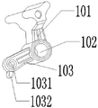
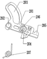
The method comprises the following specific steps: a locking and unlocking structure of a plug-in circuit breaker comprises an operating handle 1, a lock catch 2 and a shell 5, wherein the operating handle 1 comprises a handle part 101, a handle central hole 102 and a connecting part 103, the handle central hole 102 is formed in the middle of the operating handle 1, the operating handle 1 is installed on a shaft in the shell 5 through the handle central hole 102 and can rotate around the shaft, the handle part 101 is arranged outside the shell 5, and the connecting part 103 is wrapped on the shell 5; the lock catch 2 comprises a lock catch body 201, the lock catch body 201 is provided with a lock catch central hole 202, a sliding groove 203, a lock tooth 204, the lock catch 2 is rotatably arranged on the shell 5 through the handle central hole 102, the sliding groove 203 is in sliding connection with the connecting portion 103, and the lock tooth 204 extends out of the shell 5.
Preferably, the end of the connecting portion 103 is provided with a clamping boss 1032, the housing 5 is correspondingly provided with a clamping seat 5021, and when the circuit breaker is in an unlocking state, the clamping boss 1032 touches the clamping seat 5021 and is in interference fit, so that the circuit breaker is stabilized in the unlocking state.
Preferably, the latch body 201 is provided with a spring mounting groove 206, the spring mounting groove 206 is internally sleeved with a return spring 207, one end of the return spring 207 is fixed in the spring mounting groove 206, and the other end of the return spring is connected to the housing 5 in a clamping manner, so that the latch 2 is always in a locking state under the action of no external force or returns to the locking state after the external force is removed.
Preferably, a first connecting port 1031 is formed on the connecting portion 103, a mechanism link 4 is connected to the first connecting port 1031, the other end of the mechanism link 4 is connected to the rotating member 3, and the rotating member 3 is rotatably disposed on the housing 5.
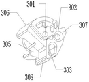
Preferably, the rotating member 3 is provided with a rotating member center hole 301, the rotating member 3 is rotatably disposed on the housing 5 through the rotating member center hole 301, the rotating member 3 is connected with the locking assembly through a connecting rod, and the rotating member 3 rotatably controls the closing and opening of the locking assembly.
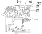
Preferably, the first limit piece 5012 and the second limit piece 5011 are disposed on the housing 5, the first limit step 307 is disposed on the right side of the rotating piece 3, the first limit step 307 abuts against the first limit piece 5012 when the circuit breaker is in the closing state, the second limit step 308 is disposed on the left side of the rotating piece 3, and the second limit step 308 abuts against the second limit piece 5011 when the circuit breaker is in the opening state, so as to limit the rotation angle of the rotating piece 3.
Preferably, the rotation member 3 on the left side of the second limit step 308 is provided with a receding groove 305, a limit surface 306 is formed between the receding groove 305 and the first limit step 307, the tail end of the lock catch body 201 is provided with an arc surface 205, when the circuit breaker is in a closing state, the first limit step 307 abuts against the first limit part 5012, at this time, the limit surface 306 faces upwards, when the lock catch body 201 retracts inwards due to an external force, the arc surface 205 abuts against the arc surface 205, the lock catch body 201 is limited from retracting inwards due to the external force, unlocking of the lock catch is prevented, when the circuit breaker is in a switching-off state, the second limit step 308 abuts against the second limit part 5011, at this time, the receding groove 305 faces upwards, when the lock catch body 201 retracts inwards due to the operating handle 1, the arc surface 205 does not touch the receding groove 305, and unlocking is easy.
Preferably, a bar-shaped sliding groove 303 is formed in the rotating part 3, the mechanism connecting rod 4 is inserted into the bar-shaped sliding groove 303 to be connected, when the breaker is in the opening and closing states, the mechanism connecting rod 4 contacts with the upper end of the bar-shaped sliding groove 303, when the breaker is in the unlocking state, the mechanism connecting rod 4 contacts with the lower end of the bar-shaped sliding groove 303, when the breaker is changed from the closing state to the unlocking state, the operating handle 1 needs to be pulled upwards, the lock catch 2 is driven to forget to retract, at the moment, the two limiting steps 308 and the two limiting parts 5011 are abutted to rotate the rotating part 2, the operating handle 1 drives the mechanism connecting rod 4 to move leftwards, and the mechanism connecting rod 4 slides in the bar-shaped sliding groove 303, so that the operating handle 1, the mechanism connecting rod 4 and the lock catch 2 have enough movement space.
Advantageous effects
1. The locking and unlocking structure of the circuit breaker is matched with the external handle, so that the circuit breaker can be unlocked only at the opening position, and compared with the existing structure on the market, the structure has fewer parts and more reliable functions;
2. the operating handle has three states, and the operating personnel is guaranteed to be very clear in state when operating the circuit breaker.
3. When the breaker is in a closing state and the breaker is inserted into the machine frame 6 in place in the closing state, the lock catch of the breaker cannot be completely retracted in the closing state, so that the limit is always kept between the lock catch and the machine frame 6, the switch can be guaranteed to be permanently detached in the closing state, and the use safety is guaranteed;
4. when the circuit breaker is in the unblock state, at this state, there is the extension characteristic cooperation of spacing boss and well seat on the handle for it can keep at this state, unless artificial square drive handle, then handle and hasp can keep the position always, makes things convenient for operating personnel to dismantle, has the bar spout on rotating the piece, can make handle and connecting rod can continue to move certain displacement, treats the return after, can continue to treat and rotate the piece motion.
Drawings
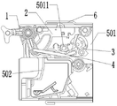
FIG. 1 is a schematic structural diagram of the brake-off state of the present invention;
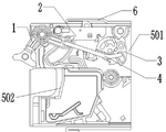
FIG. 2 is a schematic structural diagram of a closing state of the present invention;
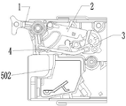
FIG. 3 is a structural diagram illustrating an unlocked state of the present invention;
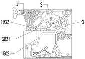
FIG. 4 is a structural diagram of the unlocking state of the present invention;
FIG. 5 is a schematic structural diagram of a closing state of the present invention;
FIG. 6 is a schematic view of the operating handle of the present invention;
FIG. 7 is a schematic view of a locking structure of the present invention;
FIG. 8 is a schematic view of a rotating member according to the present invention;
FIG. 9 is a schematic side cross-sectional view of the present invention;
fig. 10 is a schematic structural diagram of a closing state of the circuit breaker according to the present invention;
FIG. 11 is a schematic structural diagram of the circuit breaker in an open state according to the present invention;
Detailed Description
The technical solutions in the embodiments of the present invention will be described clearly and completely with reference to the accompanying drawings in the embodiments of the present invention, and it is obvious that the described embodiments are only a part of the embodiments of the present invention, rather than all embodiments, and all other embodiments obtained by a person of ordinary skill in the art without creative efforts based on the embodiments of the present invention belong to the protection scope of the present invention.
In addition, it should be understood that the terms "longitudinal", "lateral", "upper", "lower", "front", "rear", "left", "right", "top", "bottom", "inner", "outer", and the like, which indicate orientations or positional relationships based on the orientations or positional relationships illustrated in the drawings, are only used for convenience in describing the present invention, and do not indicate or imply that the device or element indicated must have the specific orientation and be operated in the specific orientation, and thus, the present invention is not limited thereto.
As shown in figures 1 to 11:
a locking and unlocking structure of a plug-in circuit breaker comprises an operating handle 1, a lock catch 2 and a shell 5, wherein the operating handle 1 comprises a handle part 101, a handle central hole 102 and a connecting part 103, the handle central hole 102 is formed in the middle of the operating handle 1, the operating handle 1 is installed on a shaft in the shell 5 through the handle central hole 102 and can rotate around the shaft, the handle part 101 is arranged outside the shell 5, and the connecting part 103 is wrapped on the shell 5; the lock catch 2 comprises a lock catch body 201, the lock catch body 201 is provided with a lock catch central hole 202, a sliding groove 203, a lock tooth 204, the lock catch 2 is rotatably arranged on the shell 5 through the handle central hole 102, the sliding groove 203 is in sliding connection with the connecting portion 103, and the lock tooth 204 extends out of the shell 5.
Wherein, connecting portion 103 end is provided with joint boss 1032, casing 5 includes shell 501 and well seat 502, and the correspondence is provided with extension characteristic joint seat 5021 on the well seat 502, and when the circuit breaker was in the unblock state, joint boss 1032 touched and interference fit with joint seat 5021, made the circuit breaker stabilize in the unblock state, need exert certain thrust when removing the unblock state, and the feedback is obvious during the installation, and the operation of being convenient for is confirmed, and of course it can also set up on shell 501 to extend characteristic joint seat 5021.
Wherein, seted up spring mounting groove 206 on the hasp body 201, the spring mounting groove 206 endotheca is equipped with reset spring 207, and reset spring 207 one end is fixed in spring mounting groove 206, and the other end joint is on casing 5 for hasp 2 is in locking state or the external force returns the back locking state after cooling down all the time under no exogenic action.
Wherein, a first connecting port 1031 is arranged on the connecting portion 103, a mechanism connecting rod 4 is connected on the first connecting port 1031, the other end of the mechanism connecting rod 4 is connected with a rotating piece 3, and the rotating piece 3 is rotatably arranged on the shell 5.
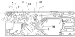
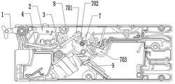
Wherein, rotating 3 and being provided with a rotation centre bore 301, rotating 3 and rotating through rotating a centre bore 301 and set up on casing 5, rotate 3 and be connected with the hasp subassembly through the connecting rod to through the combined floodgate and the separating brake of rotating 3 rotation control hasp subassemblies, specific: the rotating part 3 is provided with a balance pull rod connecting hole 302, the balance pull rod 8 is connected to the balance pull rod connecting hole 302, the other end of the balance pull rod 8 is connected with a lock catch component 7, the lock catch component 7 comprises a lock catch shell, a trip 701, a middle base 702 and a moving contact 703, when the circuit breaker is in a switching-on state, the rotating part 3 is in a balance state through the balance pull rod 8, the trip 701 and the lock catch shell, the moving contact 703 is in contact with a static contact 9 for conducting electricity, when the circuit breaker is in a switching-off state, the rotating part 3 rotates to drive the lock catch component 7 to rotate, and the moving contact 703 is separated from the static contact 9 for power failure.
The first limit piece 5012 and the second limit piece 5011 are arranged on the housing 5, the first limit step 307 is arranged on the right side of the rotating piece 3, the first limit step 307 abuts against the first limit piece 5012 when the circuit breaker is in a closing state, the second limit step 308 is arranged on the left side of the rotating piece 3, and the second limit step 308 abuts against the second limit piece 5011 when the circuit breaker is in an opening state, so that the rotating angle of the rotating piece 3 is limited.
The rotation part 3 on the left side of the second limiting step 308 is provided with a receding groove 305, a limiting surface 306 is formed between the receding groove 305 and the first limiting step 307, the tail end of the lock catch body 201 is provided with an arc surface 205, when the breaker is in a closing state, the first limiting step 307 abuts against the first limiting part 5012, the limiting surface 306 faces upwards, when the lock catch body 201 retracts inwards due to external force, the arc surface 205 abuts against the arc surface 205 to limit the lock catch body 201 from retracting inwards due to the external force, so that the lock catch is prevented from being unlocked, when the breaker is in a breaking state, the second limiting step 308 abuts against the second limiting part 5011, the receding groove 305 faces upwards, when the lock catch body 201 retracts inwards due to the operation handle 1, the arc surface 205 does not touch the receding groove 305, and the breaker is unlocked easily.
Wherein, rotating and having seted up bar spout 303 on 3, mechanism connecting rod 4 inserts and connects in the bar spout 303, and mechanism connecting rod 4 contacts bar spout 303 upper end when the circuit breaker is in separating brake and combined floodgate state, when the circuit breaker is in the unblock state mechanism connecting rod 4 contacts bar spout 303 lower extreme, when the circuit breaker is by the combined floodgate state change for the unblock state, need break off with the fingers and thumb operating handle 1 up, drive hasp 2 and inwards receive, spacing step two 308 and two locating part 5011 inconsistent rotation piece 2 can't rotate this moment, operating handle 1 will drive mechanism connecting rod 4 and move left, mechanism connecting rod 4 will slide in bar spout 303 for operating handle 1, mechanism connecting rod 4 and hasp 2 have sufficient space of movement.
In the embodiment, the sliding groove 203 is slidably connected to the connecting portion 103, and in the embodiment, it is shown that the mechanism connecting rod 4 extends into the sliding groove 203 to drive the buckle to move, but it is within the ability of those skilled in the art to replace the connecting portion 103 with a protruding feature to drive the sliding groove, or to integrate the connecting portion 103 and the mechanism connecting rod 4 without creative work, without departing from the scope of the invention.
Claims (8)
1. The utility model provides a plug-in circuit breaker locks and unlocks structure, includes operating handle (1), hasp (2), casing (5), its characterized in that: the operating handle (1) comprises a handle part (101), a handle center hole (102) and a connecting part (103), the handle center hole (102) is formed in the middle of the operating handle (1), the operating handle (1) is mounted on a shaft in the shell (5) through the handle center hole (102) and can rotate around the shaft, the handle part (101) is arranged outside the shell (5), and the connecting part (103) is wrapped on the shell (5); the lock catch (2) comprises a lock catch body (201), the lock catch body (201) is provided with a lock catch center hole (202), a sliding groove (203) and a lock tooth (204), the lock catch (2) is rotatably arranged on the shell (5) through a handle center hole (102), the sliding groove (203) is in sliding connection with the connecting portion (103), and the lock tooth (204) extends out of the shell (5).
2. The plug-in circuit breaker locking and unlocking structure of claim 1, wherein: connecting portion (103) end is provided with joint boss (1032), it is provided with joint seat (5021) to correspond on casing (5), and when the circuit breaker was in the unblock state, joint boss (1032) touched and interference fit with joint seat (5021), made the circuit breaker stabilize at the unblock state.
3. The locking and unlocking structure of the plug-in type circuit breaker according to claim 1, wherein the latch body (201) is provided with a spring mounting groove (206), a return spring (207) is sleeved in the spring mounting groove (206), one end of the return spring (207) is fixed in the spring mounting groove (206), and the other end is clamped on the housing (5).
4. The plug-in circuit breaker locking and unlocking structure according to claim 1, wherein: a first connecting port (1031) is formed in the connecting portion (103), a mechanism connecting rod (4) is connected to the first connecting port (1031), and a rotating piece (3) is connected to the other end of the mechanism connecting rod (4) and is rotatably arranged on the shell (5).
5. The structure for locking and unlocking a plug-in circuit breaker according to claim 4, wherein the rotating member (3) is provided with a rotating member center hole (301), the rotating member (3) is rotatably provided on the housing (5) through the rotating member center hole (301), the rotating member (3) is connected with the latch assembly through a connecting rod, and the closing and opening of the latch assembly are controlled by the rotation of the rotating member (3).
6. The locking and unlocking structure of the plug-in type circuit breaker according to claim 4, wherein a first limit piece (5012) and a second limit piece (5011) are provided on the housing (5), a first limit step (307) is provided on the right side of the rotating piece (3), the first limit step (307) is abutted against the first limit piece (5012) when the circuit breaker is in the closing state, a second limit step (308) is provided on the left side of the rotating piece (3), and the second limit step (308) is abutted against the second limit piece (5011) when the circuit breaker is in the opening state, thereby limiting the rotation angle of the rotating piece (3).
7. The locking and unlocking structure of the plug-in type circuit breaker according to claim 6, wherein the rotation member (3) on the left side of the second limiting step (308) is provided with a yielding groove (305), a limiting surface (306) is formed between the yielding groove (305) and the first limiting step (307), the tail end of the lock catch body (201) is provided with an arc surface (205), the first limiting step (307) is abutted against the first limiting member (5012) when the circuit breaker is in a closing state, and the second limiting step (308) is abutted against the second limiting member (5011) when the circuit breaker is in an opening state.
8. The locking and unlocking structure of the plug-in type circuit breaker according to claim 7, wherein the rotating member (3) is provided with a bar-shaped sliding slot (303), the mechanism connecting rod (4) is inserted into the bar-shaped sliding slot (303) for connection, the mechanism connecting rod (4) contacts with the upper end of the bar-shaped sliding slot (303) when the circuit breaker is in the opening and closing state, and the mechanism connecting rod (4) contacts with the lower end of the bar-shaped sliding slot (303) when the circuit breaker is in the unlocking state.
Priority Applications (1)
| Application Number | Priority Date | Filing Date | Title |
|---|---|---|---|
| CN202220391041.8U CN217361476U (en) | 2022-02-25 | 2022-02-25 | Locking and unlocking structure of plug-in circuit breaker |
Applications Claiming Priority (1)
| Application Number | Priority Date | Filing Date | Title |
|---|---|---|---|
| CN202220391041.8U CN217361476U (en) | 2022-02-25 | 2022-02-25 | Locking and unlocking structure of plug-in circuit breaker |
Publications (1)
| Publication Number | Publication Date |
|---|---|
| CN217361476U true CN217361476U (en) | 2022-09-02 |
Family
ID=83046925
Family Applications (1)
| Application Number | Title | Priority Date | Filing Date |
|---|---|---|---|
| CN202220391041.8U Active CN217361476U (en) | 2022-02-25 | 2022-02-25 | Locking and unlocking structure of plug-in circuit breaker |
Country Status (1)
| Country | Link |
|---|---|
| CN (1) | CN217361476U (en) |
Cited By (1)
| Publication number | Priority date | Publication date | Assignee | Title |
|---|---|---|---|---|
| CN114496672A (en) * | 2022-02-25 | 2022-05-13 | 江西航同电气科技有限公司 | Locking and unlocking structure of plug-in circuit breaker |
-
2022
- 2022-02-25 CN CN202220391041.8U patent/CN217361476U/en active Active
Cited By (2)
| Publication number | Priority date | Publication date | Assignee | Title |
|---|---|---|---|---|
| CN114496672A (en) * | 2022-02-25 | 2022-05-13 | 江西航同电气科技有限公司 | Locking and unlocking structure of plug-in circuit breaker |
| CN114496672B (en) * | 2022-02-25 | 2024-05-17 | 江西航同电气科技有限公司 | Plug-in circuit breaker locking and unlocking structure |
Similar Documents
| Publication | Publication Date | Title |
|---|---|---|
| CN217361476U (en) | Locking and unlocking structure of plug-in circuit breaker | |
| CN110965859B (en) | Full-automatic electronic door lock | |
| CN111485767A (en) | Electronic cabinet lock | |
| CN212517095U (en) | Locking device and circuit breaker | |
| CN210692391U (en) | Circuit breaker with anti-misoperation closing device | |
| CN210040100U (en) | Miniature circuit breaker operating device and miniature circuit breaker | |
| CN106691149B (en) | Fruit juice mixer | |
| CN210575764U (en) | Installation mechanism of plug-in circuit breaker | |
| CN109273302B (en) | Electric operating mechanism of circuit breaker | |
| CN114496672A (en) | Locking and unlocking structure of plug-in circuit breaker | |
| CN215332038U (en) | Intelligent panel lock | |
| CN213877980U (en) | Reset indicating device of residual current circuit breaker | |
| CN212934472U (en) | Vacuum circuit breaker program lock | |
| CN215332080U (en) | Intelligent cabinet lock | |
| CN212934498U (en) | Oblique slider type mounting mechanism of plug-in circuit breaker | |
| CN217239362U (en) | Plug-in circuit breaker state indicator and operating mechanism | |
| CN209958921U (en) | Door lock and electronic anti-peephole device thereof | |
| CN108565185B (en) | Leakage indication protection mechanism and leakage indication protection method of leakage circuit breaker | |
| CN210152446U (en) | Power storage type electric opening type door lock switch | |
| CN111663856A (en) | Intelligent mortise lock body | |
| CN207879056U (en) | Single tongue lock body | |
| CN212583443U (en) | Lock beam and lock | |
| CN220933989U (en) | Electric operating mechanism with locking function | |
| CN209780458U (en) | Electronic puzzle lock capable of being mechanically unlocked | |
| CN213234622U (en) | Novel sharing treasured tool to lock that charges |
Legal Events
| Date | Code | Title | Description |
|---|---|---|---|
| GR01 | Patent grant | ||
| GR01 | Patent grant |