CN217317350U - Edge grinding machine based on toughened glass production - Google Patents
Edge grinding machine based on toughened glass production Download PDFInfo
- Publication number
- CN217317350U CN217317350U CN202221288564.6U CN202221288564U CN217317350U CN 217317350 U CN217317350 U CN 217317350U CN 202221288564 U CN202221288564 U CN 202221288564U CN 217317350 U CN217317350 U CN 217317350U
- Authority
- CN
- China
- Prior art keywords
- sliding
- plate
- fixedly connected
- motor
- base
- Prior art date
- Legal status (The legal status is an assumption and is not a legal conclusion. Google has not performed a legal analysis and makes no representation as to the accuracy of the status listed.)
- Active
Links
Images


Classifications
-
- Y—GENERAL TAGGING OF NEW TECHNOLOGICAL DEVELOPMENTS; GENERAL TAGGING OF CROSS-SECTIONAL TECHNOLOGIES SPANNING OVER SEVERAL SECTIONS OF THE IPC; TECHNICAL SUBJECTS COVERED BY FORMER USPC CROSS-REFERENCE ART COLLECTIONS [XRACs] AND DIGESTS
- Y02—TECHNOLOGIES OR APPLICATIONS FOR MITIGATION OR ADAPTATION AGAINST CLIMATE CHANGE
- Y02P—CLIMATE CHANGE MITIGATION TECHNOLOGIES IN THE PRODUCTION OR PROCESSING OF GOODS
- Y02P40/00—Technologies relating to the processing of minerals
- Y02P40/50—Glass production, e.g. reusing waste heat during processing or shaping
- Y02P40/57—Improving the yield, e-g- reduction of reject rates
Landscapes
- Grinding And Polishing Of Tertiary Curved Surfaces And Surfaces With Complex Shapes (AREA)
Abstract
The utility model discloses an edging machine based on toughened glass production in the technical field of edging machines, which comprises a base, wherein a circular chute is arranged in the middle of the left side of the upper surface of the base, a pillar is fixedly connected with the middle of the left end of the upper surface of the base, a first motor is fixedly installed at the middle of the right side of the upper surface of the base, a placing plate is fixedly connected with the top end of a first motor transmission shaft, a circular sliding plate is fixedly connected with the outer edge of the bottom of the placing plate, the circular sliding plate is slidably connected with the inner cavity of the circular chute, a supporting plate is fixedly connected with the top end of the pillar, the edging machine based on toughened glass production polishes glass by moving a first sliding rod and a second sliding rod along the first sliding hole and the second sliding hole to conveniently adjust the left and right positions of a polishing wheel, and polishes glass by sliding the first sliding block and the second sliding block along the first sliding groove and the second sliding groove to drive the polishing wheel to move back and forth, the operation of being convenient for, it places the board through first motor drive and rotates and trade the limit.
Description
Technical Field
The utility model relates to an edging machine technical field specifically is an edging machine based on toughened glass production.
Background
The edging machine divide into strap edging machine, glass edging machine, stone material edging machine etc. porcelain material edging machine, toughened glass need cut former ordinary glass material when producing, and the cutting process needs polish.
Present glass edging machine has some weak points, and present polisher is polishing at present, and the dynamics of polishing and the angle of polishing is not convenient for control, leads to efficiency lower, and when using, the clamping is comparatively troublesome, and the four sides of polishing need a lot of clamping, and the operation is too loaded down with trivial details, for this reason we have proposed the edging machine based on toughened glass production.
SUMMERY OF THE UTILITY MODEL
An object of the utility model is to provide an edging machine based on toughened glass production to having proposed the present polisher of having now in solving above-mentioned background and being polished, the dynamics of polishing and angle are not convenient for control, lead to efficiency lower, and when using, the clamping is comparatively troublesome, and the four sides of polishing need clamping many times, operate too loaded down with trivial details problem.
In order to achieve the above object, the utility model provides a following technical scheme: the edge grinding machine based on toughened glass production comprises a base, wherein a circular sliding groove is formed in the middle of the left side of the upper surface of the base, a supporting column is fixedly connected to the middle of the left end of the upper surface of the base, a first motor is fixedly mounted in the middle of the right side of the upper surface of the base, a placing plate is fixedly connected to the top end of a first motor transmission shaft, a circular sliding plate is fixedly connected to the outer edge of the bottom of the placing plate and is slidably connected to the inner cavity of the circular sliding groove, a supporting plate is fixedly connected to the top end of the supporting column, an electric push rod is fixedly mounted in the middle of the right side of the bottom of the supporting plate, a rotating disc is rotatably connected to the bottom of the electric push rod, a pressing plate is fixedly connected to the bottom of the rotating disc, a first sliding hole is formed in the middle of the right side of the supporting plate, and a first sliding rod is slidably connected to the inner cavity of the first sliding hole, the utility model discloses a grinding machine, including base, first slide bar, first mounting panel, first spout, second spout, first spout, second spout, first motor shaft, second motor shaft, first mounting panel, second mounting panel, first spout, second slider's top fixedly connected with bracing piece, the top of bracing piece with the bottom fixed connection of first slider, the middle fixedly connected with mount pad of bracing piece left surface, the left surface fixed mounting of mount pad has the second motor, the left end fixed mounting of second motor shaft has the wheel of polishing.
Preferably, the middle of the right side of the upper surface of the base is provided with a first mounting groove, and the first motor is fixedly mounted in an inner cavity of the first mounting groove.
Preferably, the grinding wheel is located above the placing plate, and the placing plate is located on the same vertical line as the pressing plate.
Preferably, rubber protection pads are fixedly bonded on the upper surface of the placing plate and the bottom of the pressing plate.
Preferably, the control panel is fixedly installed at the front left end of the base, and the first motor, the electric push rod and the second motor are electrically connected with the control panel through electric wires.
Preferably, the middle of the right side surface of the support rod is fixedly connected with a handle, and the surface of the handle is sleeved with an anti-slip sleeve.
Compared with the prior art, the beneficial effects of the utility model are that:
1. this edging machine based on toughened glass production, through removing first slide bar and second slide bar along first slide opening and second slide opening, thereby adjust and remove the position about first mounting panel and second mounting panel, be convenient for adjust the bracing piece according to glass's size position about, thereby be convenient for adjust the position about the wheel of polishing, be convenient for polish the glass of equidimension not, through sliding first slider and second slider along first spout and second spout, thereby adjust the front and back position of bracing piece, the bracing piece drives the wheel of polishing and removes, thereby polish glass's edge, be convenient for operate.
2. This edging machine based on toughened glass production, through starting electric push rod, electric push rod promotes the fixed glass of clamp plate to the user of being convenient for carries out the clamping, through starting first motor, first motor drives places the board and rotates, and through the ring spout that the ring slide that places the board bottom and be equipped with and base surface were equipped with, stability when the board rotates is placed in the improvement, places the board and drives glass and rotate, and the glass of being convenient for changes limit and polishes, need not clamping once more, thereby improves the efficiency of polishing.
Drawings
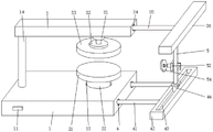
FIG. 1 is a schematic view of the present invention;
FIG. 2 is a front cross-sectional view of the present invention;
FIG. 3 is a schematic view of the base of the present invention;
fig. 4 is an enlarged schematic view of the structure of the polishing wheel adjusting mechanism of the present invention;
fig. 5 is a schematic diagram of the structure of the placing plate of the present invention.
In the figure: 1. a base; 11. a control panel; 12. a first mounting groove; 13. a circular chute; 14. a pillar; 2. a first motor; 21. placing the plate; 22. a circular ring sliding plate; 3. a support plate; 31. electrically pushing the rod; 32. rotating the disc; 33. pressing a plate; 34. a first slide hole; 35. a first slide bar; 36. a first mounting plate; 37. a first chute; 38. a first slider; 4. a second slide hole; 41. a second slide bar; 42. a second mounting plate; 43. a second chute; 44. a second slider; 5. a support bar; 51. a grip; 52. a mounting seat; 53. a second motor; 54. and (5) grinding the wheel.
Detailed Description
The technical solutions in the embodiments of the present invention will be described clearly and completely with reference to the accompanying drawings in the embodiments of the present invention, and it is obvious that the described embodiments are only some embodiments of the present invention, not all embodiments. Based on the embodiments in the present invention, all other embodiments obtained by a person skilled in the art without creative work belong to the protection scope of the present invention.
The utility model provides an edge grinding machine based on toughened glass production, which is convenient for grinding the glass with different sizes by moving a first slide bar and a second slide bar along a first slide hole and a second slide hole and adjusting the left and right positions of a grinding wheel, is convenient for grinding the glass by sliding a first slide block and a second slide block along a first slide groove and a second slide groove to drive the grinding wheel to move, is convenient for operating, pushes a pressing plate to fix the glass by starting an electric push bar, drives a placing plate to rotate to change the edge by a first motor, drives the glass to rotate by the placing plate, is convenient for grinding the glass to change the edge without clamping again, thereby improving the grinding efficiency, and please refer to figure 1-5, comprising a base 1, wherein a circular slide groove 13 is arranged in the middle of the left side of the upper surface of the base 1, a pillar 14 is fixedly connected at the middle of the left end of the upper surface of the base 1, a first motor 2 is fixedly installed at the middle of the right side of the upper surface of the base 1, the top end of a transmission shaft of the first motor 2 is fixedly connected with a placing plate 21, the outer edge of the bottom of the placing plate 21 is fixedly connected with a circular sliding plate 22, the circular sliding plate 22 is connected with an inner cavity of a circular sliding groove 13 in a sliding mode, the first motor 2 is started through the control panel 11, the first motor 2 drives the placing plate 21 to rotate, the circular sliding plate 22 arranged at the bottom of the placing plate 21 and the circular sliding groove 13 formed in the surface of the base 1 facilitate rotation of the placing plate 21, stability of the placing plate 21 during rotation is improved, and the placing plate 21 drives glass to rotate, so that edges are changed;
the top end of the pillar 14 is fixedly connected with a support plate 3, the middle part of the right side of the bottom of the support plate 3 is fixedly provided with an electric push rod 31, the bottom of the push rod of the electric push rod 31 is rotatably connected with a rotating disc 32, the bottom of the rotating disc 32 is fixedly connected with a pressing plate 33, the electric push rod 31 is started through a control panel 11, the electric push rod 31 pushes the pressing plate 33 to fix glass, the middle part of the right side of the support plate 3 is provided with a first slide hole 34, the inner cavity of the first slide hole 34 is slidably connected with a first slide rod 35, the right end of the first slide rod 35 is fixedly connected with a first mounting plate 36, the bottom of the first mounting plate 36 is provided with a first slide groove 37, the inner cavity of the first slide groove 37 is slidably connected with a first slide block 38, the front end and the rear end of the right side of the base 1 are provided with second slide holes 4, the inner cavity of the second slide holes 4 is slidably connected with a second slide rod 41, the right end of the second slide rod 41 is fixedly connected with a second mounting plate 42, and the top of the second mounting plate 42 is provided with a second slide groove 43, the inner cavity of the second sliding chute 43 is connected with a second sliding block 44 in a sliding manner, the top of the second sliding block 44 is fixedly connected with a supporting rod 5, the top of the supporting rod 5 is fixedly connected with the bottom of the first sliding block 38, the middle of the left side surface of the supporting rod 5 is fixedly connected with an installation seat 52, the left side surface of the installation seat 52 is fixedly provided with a second motor 53, the left end of a transmission shaft of the second motor 53 is fixedly provided with a polishing wheel 54, the first sliding rod 35 and the second sliding rod 41 move along the first sliding hole 34 and the second sliding hole 4, the first sliding rod 35 and the second sliding rod 41 drive the first mounting plate 36 and the second mounting plate 42 to move left and right, the first mounting plate 36 and the second mounting plate 42 drive the supporting rod 5 to move left and right, the supporting rod 5 drives the polishing wheel 54 to move left and right, so as to adjust the left and right positions of the polishing wheel 54, and the first sliding block 38 and the second sliding block 44 slide along the first sliding chute 37 and the second sliding chute 43, the first slider 38 and the second slider 44 move the support rod 5 back and forth, and the support rod 5 moves the polishing wheel 54, thereby polishing the edge of the glass.
Referring to fig. 1-5 again, a first mounting groove 12 is formed in the middle of the right side of the upper surface of the base 1, the first motor 2 is fixedly mounted in the inner cavity of the first mounting groove 12, and the first mounting groove 12 is used for mounting the first motor 2.
Referring again to fig. 1-2, the grinding wheel 54 is positioned above the placement plate 21, and the placement plate 21 is positioned on the same vertical line as the position of the pressing plate 33.
Referring to fig. 1-2 again, rubber protective pads are fixedly bonded to the upper surface of the placing plate 21 and the bottom of the pressing plate 33, and are used for preventing the glass surface from being scratched when the glass is clamped.
Referring to fig. 1, fig. 2 and fig. 4 again, a control panel 11 is fixedly installed at the left end of the front surface of the base 1, the first motor 2, the electric push rod 31 and the second motor 53 are electrically connected to the control panel 11 through electric wires, and the control panel 11 is used for controlling the start and stop of the first motor 2, the electric push rod 31 and the second motor 53.
Referring to fig. 1, 2 and 4 again, a handle 51 is fixedly connected to the middle of the right side of the support rod 5, an anti-slip sleeve is sleeved on the surface of the handle 51, and the handle 51 is used for supporting the movable support rod 5.
In specific use, when a person skilled in the art uses the glass, firstly, the glass is placed on the placing plate 21, the electric push rod 31 is started through the control panel 11, the electric push rod 31 pushes the pressing plate 33 to fix the glass, the glass is clamped, the first slide bar 35 and the second slide bar 41 are moved along the first slide hole 34 and the second slide hole 4, the first slide bar 35 and the second slide bar 41 drive the first mounting plate 36 and the second mounting plate 42 to move left and right, the first mounting plate 36 and the second mounting plate 42 drive the supporting rod 5 to move left and right, the supporting rod 5 drives the polishing wheel 54 to move left and right, so as to adjust the left and right positions of the polishing wheel 54, the polishing wheel 54 is adjusted to be attached to the edge of the glass, the second motor 53 is started through the control panel 11, the second motor 53 drives the polishing wheel 54 to rotate, the first slide block 38 and the second slide block 44 are slid along the first slide groove 37 and the second slide groove 43, the first slide block 38 and the second slide block 44 drive the supporting rod 5 to move back and forth, bracing piece 5 drives the wheel 54 of polishing and removes to polish glass's edge, accomplish the back of polishing on one side, will polish wheel 54 and put aside, start first motor 2 through control panel 11, first motor 2 drives places board 21 and rotates, through the ring spout 13 that the ring slide 22 and the base 1 surface that place board 21 bottom was equipped with were equipped with, be convenient for place board 21 and rotate, place board 21 and drive glass and rotate, thereby trade the limit, polish once more can.
It is noted that, herein, relational terms such as first and second, and the like may be used solely to distinguish one entity or action from another entity or action without necessarily requiring or implying any actual such relationship or order between such entities or actions. Also, the terms "comprises," "comprising," or any other variation thereof, are intended to cover a non-exclusive inclusion, such that a process, method, article, or apparatus that comprises a list of elements does not include only those elements but may include other elements not expressly listed or inherent to such process, method, article, or apparatus.
While the invention has been described above with reference to an embodiment, various modifications may be made and equivalents may be substituted for elements thereof without departing from the scope of the invention. In particular, as long as there is no structural conflict, the various features of the disclosed embodiments of the present invention can be used in any combination with each other, and the description of such combinations is not exhaustive in the present specification only for the sake of brevity and resource conservation. Therefore, it is intended that the invention not be limited to the particular embodiments disclosed, but that the invention will include all embodiments falling within the scope of the appended claims.
Claims (6)
1. Edging machine based on toughened glass production, including base (1), its characterized in that: the middle of the left side of the upper surface of the base (1) is provided with a circular chute (13), the middle of the left end of the upper surface of the base (1) is fixedly connected with a pillar (14), the middle of the right side of the upper surface of the base (1) is fixedly provided with a first motor (2), the top end of a transmission shaft of the first motor (2) is fixedly connected with a placing plate (21), the outer edge of the bottom of the placing plate (21) is fixedly connected with a circular sliding plate (22), the circular sliding plate (22) is slidably connected with an inner cavity of the circular chute (13), the top end of the pillar (14) is fixedly connected with a supporting plate (3), the middle of the right side of the bottom of the supporting plate (3) is fixedly provided with an electric push rod (31), the bottom of the electric push rod (31) is rotatably connected with a rotating disc (32), and the bottom of the rotating disc (32) is fixedly connected with a pressing plate (33), a first sliding hole (34) is formed in the middle of the right side of the supporting plate (3), a first sliding rod (35) is connected to an inner cavity of the first sliding hole (34) in a sliding mode, a first mounting plate (36) is fixedly connected to the right end of the first sliding rod (35), a first sliding groove (37) is formed in the bottom of the first mounting plate (36), a first sliding block (38) is connected to an inner cavity of the first sliding groove (37) in a sliding mode, second sliding holes (4) are formed in the front end and the rear end of the right side of the base (1), a second sliding rod (41) is connected to the inner cavity of the second sliding hole (4) in a sliding mode, a second mounting plate (42) is fixedly connected to the right end of the second sliding rod (41), a second sliding groove (43) is formed in the top of the second mounting plate (42), a second sliding block (44) is connected to the inner cavity of the second sliding groove (43), and a supporting rod (5) is fixedly connected to the top of the second sliding block (44), the top of bracing piece (5) with the bottom fixed connection of first slider (38), fixedly connected with mount pad (52) are located to the centre of bracing piece (5) left surface, the left surface fixed mounting of mount pad (52) has second motor (53), the left end fixed mounting of second motor (53) transmission shaft has grinding wheel (54).
2. The edging machine based on the production of toughened glass according to claim 1, characterized in that: the middle of base (1) upper surface right side is opened there is first mounting groove (12), first motor (2) fixed mounting in the inner chamber of first mounting groove (12).
3. The edging machine based on the production of toughened glass according to claim 1, characterized in that: the grinding wheel (54) is positioned above the placing plate (21), and the placing plate (21) and the pressing plate (33) are positioned on the same vertical line.
4. The edging machine based on the production of toughened glass according to claim 1, characterized in that: rubber protective pads are fixedly bonded on the upper surface of the placing plate (21) and the bottom of the pressing plate (33).
5. The edging machine based on the production of toughened glass according to claim 1, characterized in that: the positive left end fixed mounting of base (1) has control panel (11), first motor (2) electric push rod (31) with second motor (53) all through the electric wire with control panel (11) electric connection.
6. The edging machine based on the production of toughened glass according to claim 1, characterized in that: the middle of the right side surface of the support rod (5) is fixedly connected with a grip (51), and the surface of the grip (51) is sleeved with an anti-skid sleeve.
Priority Applications (1)
| Application Number | Priority Date | Filing Date | Title |
|---|---|---|---|
| CN202221288564.6U CN217317350U (en) | 2022-05-27 | 2022-05-27 | Edge grinding machine based on toughened glass production |
Applications Claiming Priority (1)
| Application Number | Priority Date | Filing Date | Title |
|---|---|---|---|
| CN202221288564.6U CN217317350U (en) | 2022-05-27 | 2022-05-27 | Edge grinding machine based on toughened glass production |
Publications (1)
| Publication Number | Publication Date |
|---|---|
| CN217317350U true CN217317350U (en) | 2022-08-30 |
Family
ID=82986946
Family Applications (1)
| Application Number | Title | Priority Date | Filing Date |
|---|---|---|---|
| CN202221288564.6U Active CN217317350U (en) | 2022-05-27 | 2022-05-27 | Edge grinding machine based on toughened glass production |
Country Status (1)
| Country | Link |
|---|---|
| CN (1) | CN217317350U (en) |
-
2022
- 2022-05-27 CN CN202221288564.6U patent/CN217317350U/en active Active
Similar Documents
| Publication | Publication Date | Title |
|---|---|---|
| CN112405269A (en) | Grinding and polishing device | |
| CN217317350U (en) | Edge grinding machine based on toughened glass production | |
| CN214237510U (en) | Corner polishing device for processing waterproof lens of lamp | |
| CN108927718B (en) | Take locating support's hand-held type polisher | |
| CN212496900U (en) | Angle grinding device for processing prism base cover plate | |
| CN214922826U (en) | Grinding machine is used in cutter production convenient to overhaul | |
| CN112757092B (en) | Surface polishing device for processing round chopping board | |
| CN211465834U (en) | Grinding machine is used in production of air conditioner injection molding of conveniently taking out material | |
| CN212886711U (en) | Diamond edging tool | |
| CN213438742U (en) | A grinding device for car dysmorphism spinning spare | |
| CN211305729U (en) | Numerical control cutter grinding machine with cutter clamping stability is good | |
| CN211639349U (en) | Self-adjusting automatic polishing machine | |
| CN217255426U (en) | Burnishing device is used in toughened glass production | |
| CN218697273U (en) | Abrasive machine with fixed polishing function | |
| CN216802830U (en) | Machining center for glass production | |
| CN211103246U (en) | Grinding machine | |
| CN214642813U (en) | Semi-automatic composite contact clamping device that polishes | |
| CN213225652U (en) | Polishing machine convenient for replacing polishing disc for plate processing | |
| CN217702754U (en) | Chopping block edging mechanism | |
| CN216731238U (en) | Abrasive grinding tool convenient for grinding and polishing stone plate | |
| CN221871383U (en) | Hardware burr polishing die | |
| CN217619620U (en) | Burr treatment facility of aluminium alloy deep-processing usefulness | |
| CN219562435U (en) | Be used for mining machinery accessory part corner grinding device | |
| CN215788721U (en) | Beryllium window cutting processing is with corner equipment of polishing | |
| CN219444647U (en) | Grinding and polishing type grinding machine adjusting mechanism |
Legal Events
| Date | Code | Title | Description |
|---|---|---|---|
| GR01 | Patent grant | ||
| GR01 | Patent grant |