CN217303007U - Outdoor unit of air conditioner and air conditioner - Google Patents
Outdoor unit of air conditioner and air conditioner Download PDFInfo
- Publication number
- CN217303007U CN217303007U CN202221059342.7U CN202221059342U CN217303007U CN 217303007 U CN217303007 U CN 217303007U CN 202221059342 U CN202221059342 U CN 202221059342U CN 217303007 U CN217303007 U CN 217303007U
- Authority
- CN
- China
- Prior art keywords
- outdoor
- bracket
- air conditioner
- side plate
- outdoor unit
- Prior art date
- Legal status (The legal status is an assumption and is not a legal conclusion. Google has not performed a legal analysis and makes no representation as to the accuracy of the status listed.)
- Active
Links
Images


Abstract
The utility model discloses an outdoor unit of an air conditioner and the air conditioner, wherein the outdoor unit comprises an outdoor side shell, a first refrigerant pipeline, a compressor, an outdoor side heat exchanger and a valve body; the first refrigerant pipeline is arranged in the outdoor shell; the compressor and the outdoor heat exchanger are both arranged in the outdoor shell and are connected in series with the first refrigerant pipeline; the valve body is connected to the end of the first refrigerant pipeline and arranged at the top of the outdoor side shell, wherein the refrigerant circulating system of the air conditioner comprises the first refrigerant pipeline and a second refrigerant pipeline positioned at the indoor side, and the valve body is suitable for being connected between the first refrigerant pipeline and the second refrigerant pipeline. According to the utility model discloses an outdoor unit, convenience of customers installs the connecting pipe that links to each other with the valve body by oneself, has practiced thrift hire professional installer's expense, has reduced the installation cost of outdoor unit.
Description
Technical Field
The utility model belongs to the technical field of the air conditioning equipment technique and specifically relates to an outdoor unit and air conditioner of air conditioner is related to.
Background
In the prior art, the heat exchanger of the outdoor unit of the air conditioner generally adopts an L-shaped heat exchanger (the cross section of the heat exchanger is L-shaped), the compressor of the outdoor unit of the air conditioner is positioned at one side of the heat exchanger and is separated from the heat exchanger by an independent space, so that the overall size of the outdoor unit of the air conditioner is larger, the utilization rate of the spatial layout is lower, and in addition, the valve body of the outdoor unit of the air conditioner is arranged at the side of the box body, which is not beneficial to a user to install an indoor unit and outdoor unit connecting pipeline by himself.
SUMMERY OF THE UTILITY MODEL
The utility model discloses aim at solving one of the technical problem that exists among the prior art at least. Therefore, the utility model provides an outdoor unit of air conditioner, outdoor unit convenience of customers installs the connecting pipe that links to each other with the valve body by oneself, has practiced thrift the expense of hiring professional installer, has reduced the installation cost of outdoor unit.
The utility model discloses still provide an air conditioner that has above-mentioned outdoor unit.
According to the utility model discloses outdoor unit of air conditioner of first aspect embodiment includes: an outdoor-side housing; the first refrigerant pipeline is arranged in the outdoor shell; the compressor and the outdoor heat exchanger are both arranged in the outdoor shell, and are connected in series with the first refrigerant pipeline; the valve body is connected to the end part of the first refrigerant pipeline and arranged at the top of the outdoor side shell, wherein the refrigerant circulating system of the air conditioner comprises the first refrigerant pipeline and a second refrigerant pipeline positioned at the indoor side, and the valve body is suitable for being connected between the first refrigerant pipeline and the second refrigerant pipeline.
According to the utility model discloses outdoor unit, convenience of customers installs the connecting pipe that links to each other with the valve body by oneself, has practiced thrift the expense of hiring professional installer, has reduced the installation cost of outdoor unit.
In some embodiments, the valve body includes a low pressure valve and a high pressure valve, and the low pressure valve and the high pressure valve are respectively connected to two ends of the first refrigerant pipeline.
In some embodiments, the valve body is disposed opposite the compressor from above and below.
In some embodiments, the outdoor side housing is formed with an access opening opposite to a length end of the outdoor side heat exchanger, and the access opening is provided with a detachable cover plate.
In some embodiments, the outdoor heat exchanger includes a first heat exchanging portion and two second heat exchanging portions, and the two second heat exchanging portions are respectively connected to two opposite ends of the first heat exchanging portion in a bent manner, so that the first heat exchanging portion and the two second heat exchanging portions jointly define a receiving cavity, and at least part of the compressor is disposed in the receiving cavity.
In some embodiments, the outdoor side housing is formed with a first air inlet and two second air inlets, the two second air inlets are respectively disposed at two opposite sides of the first air inlet, the first air inlet and the first heat exchanging portion are disposed opposite to each other, and each of the second air inlets and the second heat exchanging portion are disposed opposite to each other.
In some embodiments, the outdoor side housing includes a first side plate, a second side plate, a third side plate and a fourth side plate connected end to end in sequence, the first side plate and the third side plate are disposed opposite to each other, the second side plate and the fourth side plate are disposed opposite to each other, the first air inlet is formed in the first side plate, the two second air inlets are formed in the second side plate and the fourth side plate, respectively, and the first side plate, the second side plate and the fourth side plate are an integrated piece.
In some embodiments, the outdoor unit further includes: and the outdoor side fan is arranged opposite to the accommodating cavity and is positioned on the downstream side of the outdoor side heat exchanger in the airflow direction.
In some embodiments, the outdoor side casing includes a first side plate, a second side plate, a third side plate and a fourth side plate which are sequentially connected end to end, the first side plate and the third side plate are arranged oppositely, the second side plate and the fourth side plate are arranged oppositely, the first air inlet is formed in the first side plate, the two second air inlets are respectively formed in the second side plate and the fourth side plate, the third side plate is formed with an air outlet, an air guiding ring is arranged on the outer side of the outdoor side fan, and the air guiding ring and the third side plate are an integral piece.
In some embodiments, the outdoor unit further includes: the chassis is fixedly connected with the outdoor side shell; the bracket assembly comprises a fan bracket and an electric control module, the fan bracket comprises a first bracket and a second bracket, the first bracket is provided with a fan installation part, the two opposite ends of the fan installation part respectively correspond to a first plane and a second plane in a first direction, the first plane and the second plane are arranged in parallel at intervals and are both vertical to the first direction, the first direction is vertical to the axial direction of the fan installation part, the second bracket is arranged on the first bracket, the second bracket is provided with the electric control installation part, the electric control module is fixedly arranged on the electric control installation part, at least part of the electric control module is positioned between the first plane and the second plane, wherein the two ends of the first bracket in the second direction are respectively and fixedly connected with the outdoor side shell and the chassis, and one end of the second bracket, which is far away from the first bracket, is fixedly matched with the outdoor side heat exchanger, the second direction with the axial of fan installation department with first direction is perpendicular respectively.
In some embodiments, the second bracket further has a first fixing portion, the first fixing portion is disposed at an end of the electric control installation portion, the end is far away from the first bracket, and is fixedly matched with the outdoor heat exchanger, and the first fixing portion and the first bracket are respectively fixedly connected with the electric control module.
In some embodiments, the wind turbine support further comprises a third support disposed on the first support, the third support having a reactance mounting, the support assembly further comprising: and the reactance module is fixedly arranged on the electric control installation part.
In some embodiments, the reactance module and the electronic control module are located on the same side of the first bracket in a third direction, and the third direction is parallel to the axial direction of the fan mounting portion.
According to the utility model discloses air conditioner of second aspect embodiment, including indoor unit and according to the utility model discloses the outdoor unit of above-mentioned first aspect embodiment.
According to the utility model discloses air conditioner, through adopting foretell outdoor unit, be convenient for save air conditioner 300's installation cost.
In some embodiments, the indoor unit includes an indoor-side heat exchanger, and the air conditioner further includes: the water receiving tray is arranged on the lower side of the outdoor heat exchanger; and the water pumping part is used for pumping water in the water receiving tray to the indoor side heat exchanger.
In some embodiments, the air conditioner is a window air conditioner.
Additional aspects and advantages of the invention will be set forth in part in the description which follows and, in part, will be obvious from the description, or may be learned by practice of the invention.
Drawings
The above and/or additional aspects and advantages of the present invention will become apparent and readily appreciated from the following description of the embodiments, taken in conjunction with the accompanying drawings of which:
fig. 1 is a schematic view of an outdoor unit according to an embodiment of the present invention;
FIG. 2 is another schematic view of the outdoor unit shown in FIG. 1;
FIG. 3 is yet another schematic illustration of the outdoor unit shown in FIG. 1;
FIG. 4 is yet another schematic view of the outdoor unit shown in FIG. 1;
FIG. 5 is a schematic view of the blower mount shown in FIG. 4;
FIG. 6 is an assembled schematic view of the blower mount shown in FIG. 6;
FIG. 7 is another assembled schematic view of the blower mount shown in FIG. 6;
FIG. 8 is a further assembled schematic view of the blower mount shown in FIG. 7;
FIG. 9 is a cross-sectional view taken along line A-A of FIG. 8;
FIG. 10 is yet another assembled schematic view of the blower mount shown in FIG. 8;
FIG. 11 is a cross-sectional view taken along line B-B of FIG. 10;
FIG. 12 is a further assembled schematic view of the blower mount shown in FIG. 7;
FIG. 13 is a further assembled schematic view of the blower mount shown in FIG. 12;
FIG. 14 is a schematic diagram of an air conditioner according to one embodiment of the present invention;
fig. 15 is a schematic view of an air conditioner according to another embodiment of the present invention.
Reference numerals:
an air conditioner 300,
A water receiving tray 101, a water pumping piece 102,
An outdoor unit 100,
An outdoor side casing 1, a compressor 2, an outdoor side heat exchanger 3, a valve body 4, an outdoor side fan 5,
A chassis 6, a bracket assembly 7, an access hole 1a, a cover plate 1b,
A first side plate 11, a second side plate 12, a third side plate 13, a fourth side plate 14, a top cover 15,
A first heat exchanging part 31, a second heat exchanging part 32, a housing chamber 3a, a low pressure valve 41, a high pressure valve 42,
A first air inlet 111, a second air inlet 121, an air guiding ring 131, an air outlet net cover 132,
A fan bracket 71, an electric control module 72, a positioning bulge 72a, a reactance module 73,
A first bracket 711, a second bracket 712, a third bracket 713,
A first plate 711a, a second plate 711b,
A fan mounting part 7111, a first vent hole 7112, a second vent hole 7113,
A flange portion 7114, a third ventilation hole 7115, a second fixing portion 7116,
An electric control installation part 7121, an installation groove 7121a, a first fixing part 7122,
Detailed Description
Reference will now be made in detail to embodiments of the present invention, examples of which are illustrated in the accompanying drawings, wherein like reference numerals refer to the same or similar elements or elements having the same or similar function throughout. The embodiments described below with reference to the drawings are exemplary only for the purpose of explaining the present invention, and should not be construed as limiting the present invention.
The following disclosure provides many different embodiments, or examples, for implementing different features of the invention. In order to simplify the disclosure of the present invention, the components and arrangements of specific examples are described below. Of course, they are merely examples and are not intended to limit the present invention. Furthermore, the present invention may repeat reference numerals and/or letters in the various examples. This repetition is for the purpose of simplicity and clarity and does not in itself dictate a relationship between the various embodiments and/or configurations discussed. In addition, the present disclosure provides examples of various specific processes and materials, but one of ordinary skill in the art may recognize the applicability of other processes and/or the use of other materials.
Next, with reference to the drawings, an outdoor unit 100 according to an embodiment of the present invention is described.
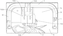
As shown in fig. 1 to 4, the outdoor unit 100 includes an outdoor side housing 1, a first refrigerant pipeline, a compressor 2, an outdoor side heat exchanger 3, and a valve body 4, the first refrigerant pipeline is disposed in the outdoor side housing 1, the compressor 2 and the outdoor side heat exchanger 3 are both disposed in the outdoor side housing 1, and the compressor 2 and the outdoor side heat exchanger 3 are both connected in series to the first refrigerant pipeline.
The refrigerant circulation system of the air conditioner 300 includes a first refrigerant pipeline and a second refrigerant pipeline located at an indoor side, and the valve body 4 is adapted to be connected between the first refrigerant pipeline and the second refrigerant pipeline.
As shown in fig. 1 to 4, the valve body 4 is connected to the end of the first refrigerant pipeline, and the valve body 4 is disposed at the top of the outdoor side housing 1, so that after the outdoor unit 100 is installed, when an operator installs a connection pipe connected to the valve body 4, since the distance between the valve body 4 and the operator is short, the operator can install the connection pipe to the connection pipe connected to the valve body 4 by himself, thereby improving the assembly convenience of the operator, saving the cost of hiring a professional installer, and reducing the installation cost of the air conditioning unit 100.
For example, for a user in a north american area, the user may install a connection pipe connected to the valve body 4 by himself/herself, and the connection pipe connects the first refrigerant pipe of the outdoor unit 100 and the second refrigerant pipe of the indoor unit, so that a professional installer is not required, the cost of hiring the professional installer is saved, and the installation cost is greatly reduced.
According to the utility model discloses outdoor unit through the top with valve body 4 design at outdoor side casing 1, has made things convenient for the user to install air conditioner 300 by oneself, has reduced air conditioner 300's installation cost.
For example, as shown in fig. 1 and 2, the outdoor side casing 1 includes a top cover 15 and a plurality of side plates, the top cover 15 and the plurality of side plates are fixed to each other, and the valve body 4 is fixed to an upper side of the top cover 15.
In some embodiments of the utility model, as shown in fig. 1 and fig. 2, valve body 4 includes low-pressure valve 41 and high-pressure valve 42, low-pressure valve 41 and high-pressure valve 42 are connected respectively at the both ends of first refrigerant pipeline, then low-pressure valve 41 is connected between the one end of first refrigerant pipeline and the one end of second refrigerant pipeline, high-pressure valve 42 is connected between the other end of first refrigerant pipeline and the other end of second refrigerant pipeline, the connecting pipe that the user of being convenient for installed by oneself and link to each other with low-pressure valve 41, install in the connecting pipe that high-pressure valve 42 links to each other, the convenience that the user installed outdoor unit 100 by oneself has further been promoted.
In some embodiments of the present invention, as shown in fig. 1 to 4, the valve body 4 and the compressor 2 are disposed opposite to each other from top to bottom, which is beneficial to reduce the distance between the valve body 4 and the compressor 2, and facilitates the arrangement of the connecting pipeline between the valve body 4 and the compressor 2; especially when the valve body 4 includes the low pressure valve 41, the low pressure valve 41 is connected between the compressor 2 and the indoor side heat exchanger in the refrigerant circulation system of the air conditioner 300, and the low pressure valve 41 is disposed opposite to the compressor 2 up and down, which is advantageous for appropriately shortening the connection line between the low pressure valve 41 and the compressor 2, saving the internal space of the outdoor side housing 1 occupied by the connection line, and facilitating the arrangement of the connection line between the low pressure valve 41 and the compressor 2.
The valve body 4 and the compressor 2 are arranged opposite to each other up and down, and it can be understood that an orthographic projection of the valve body 4 and an orthographic projection of the compressor 2 at least partially overlap on a horizontal plane.
Of course, the present application is not so limited; in other embodiments, the valve body 4 may be provided at other positions on the top of the outdoor side casing 1.
In some embodiments of the present invention, as shown in fig. 1 and fig. 2, the outdoor side housing 1 is formed with an access opening 1a, the access opening 1a can penetrate through the outdoor side housing 1 along the thickness direction of the outdoor side housing 1, the access opening 1a is opposite to one end of the length of the outdoor side heat exchanger 3, and a detachable cover plate 1b is arranged at the access opening 1 a; when the cover plate 1b is detached from the outdoor lesson housing 1, at least a part of one end of the outdoor heat exchanger 3 with the length is exposed to the access opening 1a, so that a user can clean dirt such as dust or mud on the outdoor heat exchanger 3 through the access opening 1a, or can perform maintenance operations such as maintenance on the outdoor heat exchanger 3 through the access opening 1a, thereby reducing the failure rate of the outdoor heat exchanger 3 and ensuring the normal use of the air conditioner 300.
It can be understood that the opening area of the access hole 1a can be specifically set according to actual requirements; for example, the height of the service opening 1a may be substantially the same as the height of the outdoor side heat exchanger 3 in order to ensure sufficient operation space and to facilitate cleaning and the like of the entire outdoor side heat exchanger 3.
Optionally, an air inlet (for example, a second air inlet 121 described later) is formed on the cover plate 1 b.
Optionally, in the example of fig. 3 and 4, a water pan 101 is disposed at a lower side of the outdoor heat exchanger 3 for receiving condensed water generated by the outdoor heat exchanger 3, a water pumping member 102 is further disposed in the outdoor housing 1, the water pumping member 102 is configured to pump water in the water pan 101 to the indoor heat exchanger to recycle the condensed water generated by the outdoor heat exchanger 3, so as to implement the humidification function of the air conditioner 300, and evaporate and consume the condensed water generated by the outdoor heat exchanger 3 inside the air conditioner 300, so that the outdoor unit 100 does not need to separately provide a drain pipe connected to the water pan 101 to drain the condensed water onto the outer wall, which is convenient for effectively solving the problem that the drained water may be blown to the home of a user with a low floor when the building has no special drain pipe on the outer wall, so as to avoid complaints. At this time, the access opening 1a may be further disposed opposite to the water pumping member 102, so that a portion of the access opening 1a may be exposed at the access opening 1a, so that a user may maintain the water pumping member 102 through the access opening 1a, for example, clean the water pumping member 102 to avoid the water pumping member 102 being blocked.
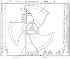
In some embodiments of the present invention, as shown in fig. 3 and 4, the outdoor heat exchanger 3 includes a first heat exchanging portion 31 and two second heat exchanging portions 32, and the two second heat exchanging portions 32 are respectively connected to two opposite ends of the first heat exchanging portion 31 in a bending manner, so that the first heat exchanging portion 31 and the two second heat exchanging portions 32 define the accommodating cavity 3a together, and the outdoor heat exchanger 3 can generally define a U-shaped structure, so that the outdoor heat exchanger 3 makes full use of the space in the outdoor side housing 1, thereby increasing the heat exchange area of the outdoor heat exchanger 3, facilitating the improvement of the heat exchange performance of the outdoor heat exchanger 3, and further improving the heat exchange performance of the air conditioner 300.
In addition, it can be understood that, compared to the technology in which the valve body is disposed at the side of the outdoor side housing, the position inside the outdoor side housing opposite to the valve body needs to provide a little space for the connection of the valve body and the pipeline, and the valve body 4 is disposed at the top of the outdoor side housing 1 in the present application, so that the valve body 4 makes more space for the outdoor side heat exchanger 3 to facilitate the arrangement of the outdoor side heat exchanger 3.
At least part of the compressor 2 is arranged in the accommodating cavity 3a, and then part of the compressor 2 is arranged in the accommodating cavity 3a, or the whole compressor 2 is arranged in the accommodating cavity 3a, so that the space in the accommodating cavity 3a is conveniently and fully utilized, the occupied spaces of the outdoor heat exchanger 3 and the compressor 2 are favorably reduced, the overall size of the outdoor unit 100 is effectively reduced under the condition that the outdoor unit 100 has the same components, and particularly the size of the outdoor unit 100 in the arrangement direction of the two second heat exchange parts 32 is reduced; of course, if the overall size of the outdoor unit 100 is not changed, the occupied space of the outdoor heat exchanger 3 and the compressor 2 is small, so that more layout space is conveniently vacated for other components, and therefore the cabinet loading capacity of the outdoor unit 100 is increased, the cabinet loading capacity of the outdoor unit 100 under the same capacity section is increased, the reasonable layout of the components is conveniently realized, and the function of the outdoor unit 100 is favorably enriched.
In some embodiments of the present invention, as shown in fig. 1 to 4, the outdoor side housing 1 is formed with a first air inlet 111 and two second air inlets 121, two second air inlets 121 are respectively disposed at two opposite sides of the first air inlet 111, and the first air inlet 111 and the first heat exchanging portion 31 are disposed relatively, each second air inlet 121 and the second heat exchanging portion 32 are disposed relatively, then the air flow at the first air inlet 111 can flow to the first heat exchanging portion 31 and exchange heat with the first heat exchanging portion 31, the air flow at the second air inlet 121 can flow to the second heat exchanging portion 32 and exchange heat with the second heat exchanging portion 32, which is beneficial to improving the heat exchange uniformity of the outdoor side heat exchanger 3, and improving the heat exchange efficiency of the outdoor side heat exchanger 3, thereby facilitating to achieve the purpose of energy saving.
It can be seen that, by arranging the first air inlet 111 opposite to the first heat exchanging portion 31 and the second air inlet 121 opposite to the second heat exchanging portion 32, the air duct inside the outdoor housing 1 can be formed into an air suction type air duct, so that both the first heat exchanging portion 31 and the second heat exchanging portion 32 exchange heat with the air flow sufficiently, the contact area between the outdoor heat exchanger 103 and the air flow is increased, and the heat exchange uniformity of the outdoor heat exchanger 103 is increased.
In some embodiments of the present invention, as shown in fig. 1-4, the outdoor side casing 1 includes a first side plate 11, a second side plate 12, a third side plate 13 and a fourth side plate 14 connected end to end in sequence, the first side plate 11 and the third side plate 13 are disposed oppositely, the second side plate 12 and the fourth side plate 14 are disposed oppositely, the first air inlet 111 is formed on the first side plate 11, the two second air inlets 121 are respectively formed on the second side plate 12 and the fourth side plate 14, the first side plate 11, the second side plate 12 and the fourth side plate 14 are an integrated piece, which facilitates saving of a connection procedure between the first side plate 11 and the second side plate 12, saving of a connection procedure between the first side plate 11 and the fourth side plate 14, and does not need to process a connection structure, which facilitates processing and assembling of the outdoor side casing 1, and simultaneously makes the overall structure of the outdoor side casing 1 more stable, and improves the structural strength of the outdoor side casing 1, thereby improving the reliability of the outdoor unit 100.
In some embodiments of the present invention, as shown in fig. 4, the outdoor unit 100 further includes an outdoor fan 5, the outdoor fan 5 is disposed opposite to the accommodating cavity 3a, and in the airflow direction, the outdoor fan 5 is located at the downstream side of the outdoor heat exchanger 3, so as to further ensure that the airflow flowing into the outdoor casing 1 from the first air inlet 111 fully contacts with the first heat exchanging portion 31, and the airflow flowing into the outdoor casing 1 from the second air inlet 121 fully contacts with the second heat exchanging portion 32, so as to ensure the air volume of the outdoor fan 5, so that the air supply effect of the outdoor fan 5 is stronger, thereby improving the cooling or heating efficiency of the air conditioner 300.
In some embodiments of the present invention, as shown in fig. 3, the outdoor side casing 1 includes a first side plate 11, a second side plate 12, a third side plate 13, and a fourth side plate 14 which are sequentially connected end to end, the first side plate 11 and the third side plate 13 are relatively disposed, the second side plate 12 and the fourth side plate 14 are relatively disposed, the first air inlet 111 is formed on the first side plate 11, the two second air inlets 121 are respectively formed on the second side plate 12 and the fourth side plate 14, the outside of the outdoor side fan 5 is provided with the air guiding ring 131, the air guiding ring 131 can guide the air flow, which is convenient for realizing the centralized blowing of the air flow, and is favorable for improving the air volume of the outdoor side fan 5.
The third side plate 13 is provided with an air outlet, the air guide ring 131 and the third side plate 13 are integrated, so that the connection procedure of the air guide ring 131 and the third side plate 13 is saved, a connection structure does not need to be processed, and the air guide ring 131 and the third side plate 13 are integrally more stable.
Optionally, in the example of fig. 1 and 3, an air outlet mesh enclosure 132 is provided at the air outlet.
In some embodiments of the present invention, as shown in fig. 3 to 5, the outdoor unit 100 further includes a chassis 6 and a bracket assembly 7, the chassis 6 is fixedly connected to the outdoor side housing 1, the bracket assembly 7 includes a blower bracket 71, the blower bracket 71 includes a first bracket 711 and a second bracket 712, the first bracket 711 has a blower mounting portion 7111, in a first direction, opposite ends of the blower mounting portion 7111 respectively correspond to a first plane and a second plane, the first plane and the second plane are arranged at a parallel interval, and the first plane and the second plane are perpendicular to the first direction, the first direction is perpendicular to an axial direction of the blower mounting portion 7111, and then the first plane and the second plane can be arranged at a radial interval along the blower mounting portion 7111, and the second bracket 712 is arranged on the first bracket 711.
Here, the axial direction of the fan installation part 7111 may be understood as the axial direction of the outdoor fan 5 installed in the fan installation part 7111. The two ends of the first bracket 711 in the second direction are fixedly connected with the outdoor side housing 1 and the chassis 102, respectively, one end of the second bracket 12 far away from the first bracket 11 is fixedly matched with the outdoor heat exchanger 103, and the second direction is perpendicular to the axial direction and the first direction of the fan mounting part 111, respectively.
For example, the first direction is a left-right direction, the axial direction of the fan installation part 7111 is a front-back direction, the second direction is an up-down direction, the left end of the fan installation part 7111 corresponds to a first plane, the first plane can pass through the left end edge of the fan installation part 7111, the right end of the fan installation part 7111 corresponds to a second plane, and the second plane can pass through the right end edge of the fan installation part 7111, so that the fan installation part 7111 is located between the first plane and the second plane in the left-right direction, the upper end of the first bracket 11 can be fixedly connected with the outdoor side housing 1, for example, the upper end of the first bracket 11 is fixedly connected with the front side plate of the outdoor side housing 1, and the lower end of the first bracket 11 can be fixedly connected with the chassis 102, so as to ensure that the bracket assembly 100 is firmly installed. Of course, the first direction is not limited thereto.
As shown in fig. 3 and 7, the bracket assembly 7 further includes an electronic control module 72, the second bracket 712 has an electronic control mounting portion 7121, the electronic control module 72 is fixedly mounted on the electronic control mounting portion 7121, and the electronic control module 72 and the electronic control mounting portion 7121 may be directly and/or indirectly fixedly connected. Wherein, at least part of the electronic control module 72 is located between the first plane and the second plane, at least part of the electronic control module 72 can be arranged opposite to the blower fan mounting part 7111 along the direction perpendicular to the first direction, and along the direction perpendicular to the first direction, the projection of the electronic control module 72 is at least partially overlapped with the projection of the blower fan mounting part 7111, so as to effectively reduce the length of the bracket assembly 7 in the first direction, and save the occupied space of the bracket assembly 7 in the first direction.
In addition, the fan mounting portion 7111 is used for mounting the outdoor fan 5, the outdoor fan 5 is used for driving airflow to flow, and at least part of the electronic control module 72 is located between the first plane and the second plane, so that at least part of the electronic control module 72 is located in a flow field generated by the airflow driven by the outdoor fan 5, and peripheral airflow of the electronic control module 72 has a certain flow velocity, so that heat of the electronic control module 72 is taken away, and the heat dissipation effect of the electronic control module 72 is improved.
When the bracket component 7 is applied to the outdoor unit 100, under the condition that the outdoor unit 100 has the same components, the length of the outdoor unit 100 in the first direction can be effectively reduced, the occupied space of the outdoor unit 100 in the first direction is saved, of course, if the length of the outdoor unit 100 in the first direction is unchanged, because the occupied space of the bracket component 7 is small, more arrangement space is convenient to vacate for other components, thereby the cabinet loading amount of the outdoor unit 100 is improved, the promotion of the cabinet loading amount of the outdoor unit 100 in the same capacity section is realized, the rationalization layout of each component is convenient to realize, and the function of the outdoor unit 100 is favorably enriched.
In some embodiments of the present invention, as shown in fig. 3-7, the second bracket 712 further has a first fixing portion 7122, the first fixing portion 7122 is disposed at an end of the electronic control installation portion 7121 away from the first bracket 711, and the first fixing portion 7122 and the first bracket 711 are respectively fixedly connected to the electronic control module 72; it can be seen that the electronic control module 72 is not only fixed to the first bracket 711, but also fixed to the second bracket 712, so as to ensure that the electronic control module 72 is firmly and reliably mounted, so as to avoid the electronic control module 72 from falling off and being damaged easily due to vibration generated by the operation of the outdoor unit 100, and meanwhile, the electronic control module 72 is fixed without affecting the matching between the electronic control module 72 and the electronic control mounting part 7121, which is beneficial to improving the mounting efficiency of the electronic control module 72.
For example, in the example of fig. 3 to 7, at least a portion of the electronic control mounting portion 7121 is supported at the bottom of the electronic control module 72, so that the electronic control mounting portion 7121 is used for carrying the electronic control module 72, and the electronic control module 72 is fixed to the first bracket 711 and the first fixing portion 7122, when the electronic control module 72 is mounted, the electronic control module 72 may be firstly placed on the electronic control mounting portion 7121, and then the electronic control module 72 is fixed to the first bracket 711 and the first fixing portion 7122; it can be seen that, in the installation process of the electronic control module 72, the electronic control installation part 7121 may have a certain limiting effect on the electronic control module 72, so as to facilitate subsequent quick fixing of the electronic control module 72, and in the subsequent fixing process of the electronic control module 72, the electronic control module 72 may not need to change positions, place postures, and the like, so as to facilitate quick installation of the electronic control module 72.
It can be understood that the fixing connection manner between the electronic control module 72 and the first bracket 711 and the fixing connection manner between the electronic control module 72 and the first fixing portion 7122 can be specifically configured according to actual requirements.
For example, in the example of fig. 5 and 7, the electronic control module 72 is fixedly coupled to the first bracket 711 by a threaded fastener; the first bracket 711 includes a first plate 711a and a second plate 711b, the first plate 711a is vertically disposed, the blower mounting part 7111 is formed on the first plate 711a, the second plate 711b is horizontally disposed, and the second plate 711b is coupled to the top of the first plate 711 a; the first plate 711a is formed with at least one second fixing portion 7116, and each second fixing portion 7116 is fixedly coupled to the electronic control module 72 by a fastener, such as a screw connection, respectively. The first fixing portion 7122 is formed with a fixing hole 71221, and a fastener is inserted through the electronic control module 72 and the fixing hole 71221 to fix the first fixing portion 7122 and the electronic control module 72.
Alternatively, in the example of fig. 3 to 5, two second fixing portions 7116 are provided, two second fixing portions 7116 are spaced along the first direction, and two second fixing portions 7116 are respectively provided at two ends of the first bracket 711 in the first direction, so that the electronic control module 72 can be firmly mounted with a smaller number of second fixing portions 7116.
In some embodiments of the utility model, as shown in fig. 4-6 and fig. 9, automatically controlled installation department 7121 passes through location structure location fit with automatically controlled module 72, location structure includes protruding 2a and locating hole 71211 in location, protruding 2a in location cooperates in locating hole 71211, in order to realize automatically controlled module 72 and automatically controlled installation department 7121's relative spacing, so that the follow-up quick fixed of automatically controlled module 72, simultaneously in the follow-up fixed process of automatically controlled module 72, can need not to adopt other devices or the manual work to realize spacing of automatically controlled module 72, be favorable to promoting the installation effectiveness of automatically controlled module 72.
It is to be understood that the positioning projection 2a is formed on the electronic control mounting portion 7121, and the positioning hole 71211 is formed on the electronic control module 72; alternatively, the positioning projection 2a is formed on the electronic control module 72, and the positioning hole 71211 is formed on the electronic control mounting part 7121; alternatively, when there are a plurality of positioning protrusions 2a, at least one of the positioning protrusions 2a is formed on the electronic control module 72 and the rest is formed on the electronic control mounting portion 7121, and at this time, at least one of the positioning holes 71211 is formed on the electronic control mounting portion 7121 and the rest is formed on the electronic control module 72. The number of the positioning protrusions 2a and the positioning holes 71211 may be the same or different, one or more positioning protrusions 2a may be provided, and one or more positioning holes 71211 may be provided.
For example, in the example of fig. 4-6 and 9, the positioning structure includes a plurality of positioning protrusions 2a and a plurality of positioning holes 71211, each positioning protrusion 2a is correspondingly engaged with one positioning hole 71211, a plurality of positioning holes 71211 are formed on the electronic control mounting portion 7121, and the plurality of positioning holes 71211 include a first positioning hole and a second positioning hole, which may be spaced apart substantially along a diagonal direction of the electronic control mounting portion 7121, so as to achieve the position limitation of the electronic control module 72 relative to the electronic control mounting portion 7121 in two mutually perpendicular directions, and ensure the position limitation of the electronic control module 72 is reliable.
In some embodiments of the present disclosure, as shown in fig. 3-7, the second bracket 712 cooperates with the first bracket 711 to define a mounting groove 7121a, the mounting groove 7121a is recessed toward a direction near a central axis of the blower mounting portion 7111 in a second direction, the electronic control module 72 cooperates with the mounting groove 7121a, and the second direction is perpendicular to the axial direction and the first direction of the blower mounting portion 7111, respectively. Therefore, the radial distance between the central axes of the electric control module 72 and the fan mounting part 7111 can be properly reduced, the airflow around the electric control module 72 can have proper flow velocity, the heat dissipation effect of the electric control module 72 can be ensured, the blocking effect of the electric control module 72 on the airflow can be weakened, and the blocking of the electric control module 72 on the airflow and the heat dissipation of the electric control module 72 can be considered conveniently.
For example, taking the first direction as the left-right direction, the axial direction of the fan mounting portion 7111 as the front-back direction, and the second direction as the up-down direction, in the example of fig. 3 to 7, the second bracket 712 is disposed on the upper portion of the first bracket 711, the second bracket 712 is located above the fan mounting portion 7111, and the mounting groove 7121a is recessed downward, which is beneficial to properly reduce the distance between the electronic control module 72 and the central axis of the fan mounting portion 7111 in the up-down direction, so that the electronic control module 72 is in a relatively proper position with respect to the central axis of the fan mounting portion 7111.
Of course, the second bracket 712 may also be provided at a lower portion of the first bracket 711, and the mounting groove 7121a may still be constructed in a groove structure having an open top side.
It is understood that, in the present application, the mounting groove 7121a may be defined by the second bracket 712 alone or the second bracket 712 and the first bracket 711 together.
In some embodiments, as shown in fig. 3-7, the second bracket 712 cooperates with the first bracket 711 to define a mounting groove 7121a, in the second direction, the mounting groove 7121a is recessed toward a direction close to the central axis of the blower mounting portion 7111, the electronic control module 72 is fitted in the mounting groove 7121a, a wall surface of the mounting groove 7121a is in positioning fit with the electronic control module 72 through a positioning structure, the positioning structure includes a positioning protrusion 2a and a positioning hole 71211, and the positioning protrusion 2a is fitted in the positioning hole 71211, so as to achieve quick positioning fit of the electronic control module 72 and the mounting groove 7121a, which is beneficial to improving the assembly efficiency of the electronic control module 72.
In the example of fig. 3-7, the positioning hole 71211 is formed on the bottom wall of the mounting groove 7121a, and the positioning protrusion 2a is formed on the bottom surface of the electronic control module 72, so that when the electronic control module 72 is fitted in the mounting groove 7121a, the positioning protrusion 2a can be fitted in the positioning hole 71211a, and the electronic control module 72 can be quickly limited. Of course, the positioning projection 2a may also be formed on the wall surface of the mounting groove 7121a, and the positioning hole 71211 may be formed on the electronic control module 72.
In some embodiments of the utility model, as shown in fig. 5 and 7, first support 711 is formed with first ventilation hole 7112, first ventilation hole 7112 sets up with fan installation department 7111 interval, and first ventilation hole 7112 sets up with electronic control module 72 relatively, make at least part of electronic control module 72 can expose in first ventilation hole 7112 department, be favorable to reducing the area that covers of first support 711 to electronic control module 72, and the air current of first ventilation hole 7112 department can carry out the heat exchange to the part of exposing at the electronic control module 72 of first ventilation hole 7112 department, in order to take away the heat of electronic control module 72 in time, realize the good heat dissipation of electronic control module 72, be favorable to reducing the temperature of electronic control module 72, guarantee that electronic control module 72 normally works.
For example, the first vent holes 7112 and the blower mounting portion 7111 may be spaced apart in a radial direction of the blower mounting portion 7111; in the example of FIGS. 5 and 7, the first vent 7112 is spaced above the blower mounting portion 7111 and the electronic control module 72 is spaced above the blower mounting portion 7111; of course, the first ventilation holes 7112 may be disposed below the blower mounting portion 7111 at intervals, and the electronic control module 72 may be disposed below the blower mounting portion 7111 at intervals.
In some embodiments of the present invention, as shown in fig. 5, the second frame 712 and the first frame 711 are separate components, and then the second frame 712 and the first frame 711 are separately formed, which is favorable for simplifying the structure of the first frame 711 and the second frame 712, and reduces the processing difficulty.
Of course, the second frame 712 may also be a single piece with the first frame 711, such as a single bent piece of the first frame 711 and the second frame 712.
In some embodiments of the present invention, as shown in fig. 7 and 11, the blower support 71 further includes a third support 713, the third support 713 is disposed on the first support 711, and the third support 713 has a reactance mounting portion 7131, the support assembly 7 further includes a reactance module 3, the reactance module 3 is fixedly disposed on the reactance mounting portion 7131, so that the reactance module 3 and the reactance mounting portion 7131 may be directly and fixedly connected, and/or indirectly and fixedly connected; it can be seen that the electronic control module 72 and the electronic control module 3 are both indirectly fixed to the first bracket 711, which facilitates reasonable utilization of the arrangement space on the first bracket 711, and meanwhile, since the outdoor fan 5 of the outdoor unit 100 is installed on the fan installation part 7111, the first bracket 711, the second bracket 712 and the third bracket 713 are provided, which facilitates realization of the modular installation of the outdoor fan 5, the electronic control module 72 and the reactance module 3, facilitates realization of the modular design of the outdoor unit 100, and facilitates assembly of the outdoor unit 100.
In some embodiments of the present invention, as shown in fig. 7 and 11, the reactance module 3 and the electronic control module 72 are located at the same side of the first bracket 711 in the third direction, the third direction is parallel to the axial direction of the fan mounting portion 7111, and then the third direction is perpendicular to the first direction, which facilitates the compact arrangement of the reactance module 3 and the electronic control module 72, and is beneficial to saving the occupied space of the bracket assembly 7, so as to vacate more arrangement space for other components of the outdoor unit 100.
In some embodiments of the utility model, as shown in fig. 5 and 7, first support 711 is formed with second through-air hole 7113, second through-air hole 7113 sets up with fan installation department 7111 interval, and second through-air hole 7113 sets up with reactance module 3 relatively, make at least part of reactance module 3 can expose in second through-air hole 7113 department, be favorable to reducing the area that covers of first support 711 to reactance module 3, and the air current of second through-air hole 7113 department can carry out the heat exchange to the part of exposing reactance module 3 in second through-air hole 7113 department, and the heat of electric reactance module 3 is walked away in time, realize the good heat dissipation of reactance module 3, be favorable to reducing reactance module 3's temperature, guarantee reactance module 3 normal work.
For example, the second vent holes 7113 and the fan mounting portion 7111 may be spaced apart in a radial direction of the fan mounting portion 7111; in the example of fig. 1 and 4, the second ventilation holes 7113 are spaced above the fan mounting portion 7111, and the reactance module 2 is also disposed above the fan mounting portion 7111; of course, the second ventilation hole 7113 may be disposed below the fan mounting portion 7111 at an interval, and in this case, the reactance module 3 may be disposed below the fan mounting portion 7111.
For example, in the example of fig. 5 and 7, the first bracket 711 is formed with a first vent hole 7112, a second vent hole 7113, and a third vent hole 7115, the first vent hole 7112 and the second vent hole 113 are spaced above the blower mounting portion 7111, and the third vent hole 7115 is spaced below the blower mounting portion 7111 to further weaken the blocking of the air flow by the first bracket 711.
In some embodiments of the utility model, as shown in fig. 5, third support 713 and first support 711 are for dividing the body spare, then third support 713 and first support 711 are the shaping of processing alone respectively, are favorable to simplifying the structure of first support 711 and third support 713, reduce the processing degree of difficulty.
Of course, the present application is not limited thereto; in other embodiments, the third supporting frame 713 and the first supporting frame 711 may be a single piece, for example, the first supporting frame 711 and the second supporting frame 712 are an integral bending piece.
In some embodiments of the present invention, as shown in fig. 5, 7 and 11, the first bracket 711 has the flange portions 7114 at two ends in the first direction respectively, and two flange portions 7114 are all fixedly connected to the third bracket 713, for example, each flange portion 7114 is fixed to the third bracket 713 through a threaded fastener, so as to ensure that the third bracket 713 is stably fixed to the first bracket 711, so that the first bracket 711 and the third bracket 713 are connected as a whole, thereby ensuring that the reactance module 3 is reliably installed.
Optionally, in the example of fig. 5, the surface of the flange portion 7114 is formed with ribs to enhance the structural strength of the flange portion 7114, and further ensure that the third support 713 is firmly installed.
In some embodiments of the present invention, as shown in fig. 4, 5, 7 and 9, the bracket assembly 7 further includes an outdoor fan 5, the outdoor fan 5 is mounted on the fan mounting portion 7111, the outdoor fan 5 is electrically connected to the electronic control module 72, the outdoor fan 5 and the electronic control module 72 are respectively located on two sides of the first bracket 711 in a third direction, the third direction is parallel to the axial direction of the fan mounting portion 7111, and then the third direction is perpendicular to the first direction; that is to say, in the axial of fan installation department 7111, outdoor side fan 5 and electric control module 72 are located the heterolateral of first support 711 respectively, then electric control module 72's setting is difficult for taking place to interfere with outdoor side fan 5, be convenient for guarantee that outdoor side fan 5 has sufficient running space, be favorable to avoiding simultaneously making occupation space of bracket component 7 great because of guaranteeing that electric control module 72 does not interfere with outdoor side fan 5, thereby through the relative position of reasonable setting outdoor side fan 5 and electric control module 72, be convenient for rational utilization and arrange the space, save occupation space of bracket component 7.
In some embodiments, as shown in fig. 4, 5, 7 and 9, the bracket assembly 7 includes an electronic control module 72, a reactance module 3 and an outdoor side fan 5, the outdoor side fan 5 and the electronic control module 72 are respectively located at two sides of the first bracket 711 in the third direction, the reactance module 3 and the electronic control module 72 are located at the same side of the first bracket 711 in the third direction, and then the reactance module 3 and the outdoor side fan 5 are also respectively located at opposite sides of the first bracket 711 in the third direction, so that the reactance module 3 is also not easily interfered with the outdoor side fan 5, and it is further convenient to ensure that the outdoor side fan 5 has a sufficient operating space.
In some embodiments of the present invention, as shown in fig. 4, fig. 8 and fig. 13, the minimum distance between the central axes of the electronic control module 72 and the outdoor side fan 5 is smaller than the radius of the outdoor side fan 5, and then the preset cylindrical surface coaxial with the outdoor side fan 5 is made, the radius of the preset cylindrical surface is equal to the radius of the outdoor side fan 5, at least a part of the electronic control module 72 is located inside the preset cylindrical surface, so that the air fluidity of the position where the electronic control module 72 is located is better, which is beneficial to better heat dissipation of the electronic control module 72, and is convenient for properly weakening the blocking effect of the electronic control module 72 on the air flow of the outdoor side fan 5, and is particularly suitable for an axial flow fan.
It is to be understood that the fixing manner between the end of the second bracket 712 far from the first bracket 711 and the outdoor heat exchanger 103 is not particularly limited, and for example, the fixing of the second bracket 712 and the outdoor heat exchanger 103 may be achieved by a fastener, or the fixing of the second bracket 712 and the outdoor heat exchanger 103 may be achieved by the fitting (e.g., the snap fit, etc.) of the second bracket 712 and the outdoor heat exchanger 103.
In some embodiments of the present invention, as shown in fig. 3, 4, 7 and 10, the outdoor heat exchanger 103 includes a first heat exchanging portion 1031 and two second heat exchanging portions 1032, and the two second heat exchanging portions 1032 are respectively connected to two opposite ends of the first heat exchanging portion 1031 in the first direction in a bending manner, so that the first heat exchanging portion 1031 and the two second heat exchanging portions 1032 define the accommodating chamber 103a together, the outdoor heat exchanger 103 may generally define a U-shaped structure, and the accommodating chamber 103a is located in the U-shaped structure; at least part of the electronic control module 72 and at least part of the compressor 104 of the outdoor unit 100 are disposed in the accommodating chamber 103 a.
Compare in some techniques, the L type structure is injectd to the outdoor heat exchanger, the outdoor side casing 1 inner space is convenient for utilize better in the arrangement of outdoor heat exchanger 103 in this application, reduce the length of outdoor unit 100 on the first direction, save the space that outdoor unit 100 took up on the first direction, perhaps, the length of outdoor unit 100 on the first direction is unchangeable, be favorable to vacating more arrangement space for other parts, promote the dress cabinet volume of outdoor unit 100, thereby further realize the obvious promotion of the dress cabinet volume of outdoor unit 100 under the same ability section. In addition, this application is convenient for increase outdoor heat exchanger 103's heat transfer area, is favorable to promoting outdoor heat exchanger 103's heat transfer performance to promote outdoor unit 100's performance.
For example, in the example of fig. 4, the outdoor heat exchanger 103 is fixedly connected to both the outdoor side housing 1 and the chassis 102, no partition plate is provided between the outdoor side fan 5 and the compressor 104, and the outdoor side fan 5 and the compressor 104 are located between the two second heat exchange portions 1032 in the first direction.
Optionally, in the examples of fig. 3 and 4, the outdoor side housing 1 is formed with a first air inlet 111 and two second air inlets 121, the two second air inlets 121 are respectively disposed at two opposite sides of the first air inlet 111 in the first direction, and the first air inlet 111 is disposed opposite to the first heat exchange portion 1031, so that the airflow at the first air inlet 111 flows to the first heat exchange portion 1031, each second air inlet 121 is disposed opposite to the second heat exchange portion 1032, so that the airflow at each second air inlet 121 flows to the corresponding second heat exchange portion 1032, which is beneficial to improving the heat exchange uniformity of the outdoor heat exchanger 103, improving the heat exchange efficiency of the outdoor heat exchanger 103, and thus facilitating achieving the purpose of saving energy.
It can be seen that, because the outdoor fan 5 is arranged opposite to the accommodating cavity 103a, and in the airflow direction, the outdoor fan 5 may be located at the downstream side of the outdoor heat exchanger 103, that is, the airflow flowing into the outdoor housing 1 from the air inlet first flows through the outdoor heat exchanger 103 and then flows toward the outdoor fan 5, so that the air duct of the outdoor unit 100 is configured as an air suction type air duct, so as to increase the contact area between the outdoor heat exchanger 103 and the airflow, thereby increasing the heat exchange uniformity of the outdoor heat exchanger 103 and increasing the heat exchange efficiency.
It is understood that, in the present application, the outdoor unit 100 may be used for the single type air conditioner 300 as well as the split type air conditioner 300.
The air conditioner 300 according to the embodiment of the second aspect of the present invention includes an indoor unit 200 and an outdoor unit 100 according to the embodiment of the first aspect of the present invention.
According to the embodiment of the present invention, the air conditioner 300 is convenient to save the installation cost of the air conditioner 300 by adopting the outdoor unit 100.
In some embodiments of the present invention, referring to fig. 4, the indoor unit 200 includes an indoor side heat exchanger, the air conditioner 300 further includes a water pan 101 and a water pumping member 102, the water pan 101 is disposed at the lower side of the outdoor side heat exchanger 3; the water pumping piece 102 is used for pumping water in the water pan 101 to the indoor side heat exchanger, the risk that the water in the water pan 101 is frozen in the cold weather is reduced by consuming the water in the water pan 101, the water pan 101 is prevented from being blocked, and in addition, the water in the water pan 101 is pumped to the indoor side heat exchanger, so that the indoor humidification can be realized, the humidity of indoor air is increased, and the comfort of users is improved; in addition, by circulating and consuming the water of the drip pan 101 in the air conditioner 300, the water of the drip pan 101 does not need to be discharged, and a problem that the discharged water is blown or flowed to the home of a user in a low floor by wind to cause complaints is avoided.
Optionally, a plurality of water pumping members 102 (for example, water pumps) are provided, and the plurality of water pumping members 102 includes a first water pumping member provided at one end of the length of the water collector 101 and a second water pumping member provided at the other end of the length of the water collector 101; of course, the water pumping member 102 may be one.
In some embodiments, as shown in fig. 3 and 4, the outdoor heat exchanger 3 includes a first heat exchanging portion 31 and two second heat exchanging portions 32, and the two second heat exchanging portions 32 are respectively connected to two opposite ends of the first heat exchanging portion 31 in a bent manner, so that the outdoor heat exchanger 3 substantially defines a U-shaped structure, the water receiving tray 101 matches with the shape of the outdoor heat exchanger 3, and the water receiving tray 101 also defines the U-shaped structure.
In some embodiments of the present invention, the air conditioner 300 is a window type air conditioner. Of course, the air conditioner 300 may also be a wall-mounted air conditioner 300, a mobile air conditioner 300, or the like.
In some embodiments of the present invention, referring to fig. 14 and 15, the window type air conditioner is supported on a window of a wall body, a movable window is provided in the window, and a receiving groove 300a is defined between the indoor unit 200 and the outdoor unit 100. In the example of fig. 14, the top side, the left side, and the right side of the receiving groove 300a are open such that at least a portion of the window may protrude into the receiving groove 300 a; in the example of fig. 15, the bottom side, the left side, and the right side of the receiving groove 300a are opened so that a portion of the wall body at the window may be inserted into the receiving groove 300a, in which case the window type air conditioner may be formed in a substantially saddle shape.
In the description of the present invention, it should be understood that the terms "length", "upper", "lower", "front", "left", "right", "top", "bottom", "inner", "outer", and the like indicate orientations or positional relationships based on the orientations or positional relationships shown in the drawings, and are only for convenience of description and simplicity of description, but do not indicate or imply that the device or element referred to must have a particular orientation, be constructed and operated in a particular orientation, and therefore, should not be construed as limiting the present invention. Furthermore, a feature defined as "first" or "second" may explicitly or implicitly include one or more of that feature. In the description of the present invention, "a plurality" means two or more unless otherwise specified.
In the description of the present invention, it is to be noted that, unless otherwise explicitly specified or limited, the terms "mounted," "connected," and "connected" are to be construed broadly, and may be, for example, fixedly connected, detachably connected, or integrally connected; can be mechanically or electrically connected; they may be connected directly or indirectly through intervening media, or they may be interconnected between two elements. The specific meaning of the above terms in the present invention can be understood in specific cases to those skilled in the art.
In the description herein, references to the description of the term "one embodiment," "some embodiments," "an illustrative embodiment," "an example," "a specific example," or "some examples" or the like mean that a particular feature, structure, material, or characteristic described in connection with the embodiment or example is included in at least one embodiment or example of the present invention. In this specification, the schematic representations of the terms used above do not necessarily refer to the same embodiment or example. Furthermore, the particular features, structures, materials, or characteristics described may be combined in any suitable manner in any one or more embodiments or examples.
While embodiments of the present invention have been shown and described, it will be understood by those of ordinary skill in the art that: various changes, modifications, substitutions and alterations can be made to the embodiments without departing from the principles and spirit of the invention, the scope of which is defined by the claims and their equivalents.
Claims (16)
1. An outdoor unit of an air conditioner, comprising:
an outdoor-side housing;
the first refrigerant pipeline is arranged in the outdoor shell;
the compressor and the outdoor heat exchanger are both arranged in the outdoor shell, and are connected in series with the first refrigerant pipeline;
a valve body connected to an end of the first refrigerant pipe and disposed at a top of the outdoor side housing,
the refrigerant circulating system of the air conditioner comprises a first refrigerant pipeline and a second refrigerant pipeline positioned at the indoor side, and the valve body is suitable for being connected between the first refrigerant pipeline and the second refrigerant pipeline.
2. The outdoor unit of an air conditioner according to claim 1, wherein the valve body includes a low pressure valve and a high pressure valve, and the low pressure valve and the high pressure valve are respectively connected to both ends of the first refrigerant pipe.
3. The outdoor unit of an air conditioner according to claim 1, wherein the valve body is disposed opposite to the compressor in an up-down direction.
4. The outdoor unit of an air conditioner according to claim 1, wherein said outdoor side casing is formed with an access opening which is opposed to a length end of said outdoor side heat exchanger, and said access opening is provided with a detachable cover plate.
5. The outdoor unit of the air conditioner according to any one of claims 1 to 4, wherein the outdoor side heat exchanger includes a first heat exchanging portion and two second heat exchanging portions, and the two second heat exchanging portions are respectively connected to opposite ends of the first heat exchanging portion in a bent manner, so that the first heat exchanging portion and the two second heat exchanging portions together define a receiving cavity, and at least part of the compressor is disposed in the receiving cavity.
6. The outdoor unit of an air conditioner according to claim 5, wherein said outdoor side housing is formed with a first air inlet and two second air inlets, said two second air inlets are respectively provided at opposite sides of said first air inlet, and said first air inlet is provided opposite to said first heat exchanging portion, and each of said second air inlets is provided opposite to said second heat exchanging portion.
7. The outdoor unit of an air conditioner according to claim 6, wherein said outdoor side casing includes a first side plate, a second side plate, a third side plate and a fourth side plate which are connected end to end, said first side plate and said third side plate being disposed opposite to each other, said second side plate and said fourth side plate being disposed opposite to each other, said first air intake opening is formed in said first side plate, and two said second air intake openings are formed in said second side plate and said fourth side plate, respectively,
the first side panel, the second side panel, and the fourth side panel are one piece.
8. The outdoor unit of an air conditioner according to claim 6, further comprising:
and the outdoor side fan is arranged opposite to the accommodating cavity and is positioned on the downstream side of the outdoor side heat exchanger in the airflow direction.
9. The outdoor unit of an air conditioner according to claim 8, wherein said outdoor side casing includes a first side plate, a second side plate, a third side plate and a fourth side plate which are connected end to end, said first side plate and said third side plate being disposed opposite to each other, said second side plate and said fourth side plate being disposed opposite to each other, said first air intake opening is formed in said first side plate, two of said second air intake openings are formed in said second side plate and said fourth side plate, respectively, said third side plate is formed with an air outlet opening,
and an air guide ring is arranged on the outer side of the outdoor fan, and the air guide ring and the third side plate are integrated.
10. The outdoor unit of an air conditioner according to claim 1, further comprising:
the chassis is fixedly connected with the outdoor side shell;
a bracket assembly, the bracket assembly includes a fan bracket and an electric control module, the fan bracket includes a first bracket and a second bracket, the first bracket has a fan installation part, in a first direction, the opposite ends of the fan installation part correspond to a first plane and a second plane respectively, the first plane and the parallel interval of the second plane are arranged and all perpendicular to the first direction, the first direction is perpendicular to the axial direction of the fan installation part, the second bracket is arranged on the first bracket, the second bracket has an electric control installation part, the electric control module is fixedly arranged on the electric control installation part, and at least part of the electric control module is positioned between the first plane and the second plane,
the two ends of the first bracket in the second direction are respectively and fixedly connected with the outdoor side shell and the chassis, one end of the second bracket, which is far away from the first bracket, is fixedly matched with the outdoor side heat exchanger, and the second direction is respectively vertical to the axial direction of the fan installation part and the first direction.
11. The outdoor unit of an air conditioner according to claim 10, wherein the second bracket further has a first fixing portion, the first fixing portion is provided at an end of the electric control mounting portion, which is far from the first bracket, and is fixedly engaged with the outdoor side heat exchanger, and the first fixing portion and the first bracket are respectively fixedly connected with the electric control module.
12. The outdoor unit of an air conditioner according to claim 10, wherein said fan bracket further includes a third bracket provided on said first bracket and having a reactance mounting portion,
the bracket assembly further includes:
and the reactance module is fixedly arranged on the reactance installation part.
13. The outdoor unit of an air conditioner according to claim 12, wherein the reactance module and the electric control module are located on the same side of the first bracket in a third direction, and the third direction is parallel to the axial direction of the fan mounting portion.
14. An air conditioner characterized by comprising an indoor unit and an outdoor unit of the air conditioner according to any one of claims 1 to 13.
15. The air conditioner of claim 14, wherein the indoor unit includes an indoor-side heat exchanger, the air conditioner further comprising:
the water receiving tray is arranged on the lower side of the outdoor heat exchanger;
and the water pumping part is used for pumping water in the water receiving tray to the indoor side heat exchanger.
16. An air conditioner according to claim 14 or 15 wherein the air conditioner is a window air conditioner.
Priority Applications (1)
| Application Number | Priority Date | Filing Date | Title |
|---|---|---|---|
| CN202221059342.7U CN217303007U (en) | 2022-04-30 | 2022-04-30 | Outdoor unit of air conditioner and air conditioner |
Applications Claiming Priority (1)
| Application Number | Priority Date | Filing Date | Title |
|---|---|---|---|
| CN202221059342.7U CN217303007U (en) | 2022-04-30 | 2022-04-30 | Outdoor unit of air conditioner and air conditioner |
Publications (1)
| Publication Number | Publication Date |
|---|---|
| CN217303007U true CN217303007U (en) | 2022-08-26 |
Family
ID=82915949
Family Applications (1)
| Application Number | Title | Priority Date | Filing Date |
|---|---|---|---|
| CN202221059342.7U Active CN217303007U (en) | 2022-04-30 | 2022-04-30 | Outdoor unit of air conditioner and air conditioner |
Country Status (1)
| Country | Link |
|---|---|
| CN (1) | CN217303007U (en) |
-
2022
- 2022-04-30 CN CN202221059342.7U patent/CN217303007U/en active Active
Similar Documents
| Publication | Publication Date | Title |
|---|---|---|
| CN108224566B (en) | Air supply assembly and cabinet air conditioner indoor unit with same | |
| KR20170020146A (en) | Indoor unit for air conditoiner | |
| CN111059627A (en) | Wall-hung type cabinet air conditioner | |
| CN216557834U (en) | Refrigeration device | |
| JP3315317B2 (en) | Air conditioner | |
| CN217303007U (en) | Outdoor unit of air conditioner and air conditioner | |
| CN216644353U (en) | Air conditioner indoor unit and air conditioner | |
| CN216557833U (en) | Refrigeration device | |
| CN212179060U (en) | Air conditioner | |
| CN212179049U (en) | Integral air conditioner | |
| CN117006523A (en) | Outdoor unit of air conditioner and air conditioner | |
| CN212618756U (en) | Cabinet air conditioner and air conditioner | |
| CN217303013U (en) | Bracket component for air conditioner outdoor unit, air conditioner outdoor unit and air conditioner | |
| CN220624361U (en) | Water pan and air conditioner indoor unit | |
| CN212179061U (en) | Integrated air conditioner | |
| CN113007815A (en) | Air conditioner | |
| CN219841590U (en) | Suspended ceiling type indoor unit | |
| CN219063598U (en) | Indoor unit of air conditioner | |
| CN220689209U (en) | Pipeline type air conditioner indoor unit | |
| CN211695167U (en) | Integrated air conditioner | |
| CN219494244U (en) | Air duct machine | |
| CN219433468U (en) | Heat exchange device and air conditioner | |
| CN214501457U (en) | Indoor unit of air conditioner | |
| CN218033382U (en) | Air duct machine | |
| CN216522070U (en) | Integrated air conditioner |
Legal Events
| Date | Code | Title | Description |
|---|---|---|---|
| GR01 | Patent grant | ||
| GR01 | Patent grant |