CN217291808U - Aluminum product processing grinding device - Google Patents
Aluminum product processing grinding device Download PDFInfo
- Publication number
- CN217291808U CN217291808U CN202220803412.9U CN202220803412U CN217291808U CN 217291808 U CN217291808 U CN 217291808U CN 202220803412 U CN202220803412 U CN 202220803412U CN 217291808 U CN217291808 U CN 217291808U
- Authority
- CN
- China
- Prior art keywords
- threaded rod
- platform
- driving
- gear
- belt
- Prior art date
- Legal status (The legal status is an assumption and is not a legal conclusion. Google has not performed a legal analysis and makes no representation as to the accuracy of the status listed.)
- Active
Links
Images


Classifications
-
- Y—GENERAL TAGGING OF NEW TECHNOLOGICAL DEVELOPMENTS; GENERAL TAGGING OF CROSS-SECTIONAL TECHNOLOGIES SPANNING OVER SEVERAL SECTIONS OF THE IPC; TECHNICAL SUBJECTS COVERED BY FORMER USPC CROSS-REFERENCE ART COLLECTIONS [XRACs] AND DIGESTS
- Y02—TECHNOLOGIES OR APPLICATIONS FOR MITIGATION OR ADAPTATION AGAINST CLIMATE CHANGE
- Y02P—CLIMATE CHANGE MITIGATION TECHNOLOGIES IN THE PRODUCTION OR PROCESSING OF GOODS
- Y02P70/00—Climate change mitigation technologies in the production process for final industrial or consumer products
- Y02P70/10—Greenhouse gas [GHG] capture, material saving, heat recovery or other energy efficient measures, e.g. motor control, characterised by manufacturing processes, e.g. for rolling metal or metal working
Abstract
The utility model discloses an aluminum product processing grinding device relates to the aluminum product technical field that polishes, include: the clamping assembly comprises a platform, a threaded rod, clamping blocks and a first driving part, wherein the threaded rod is rotatably connected to the platform, two sections of external threads with opposite directions are arranged on the threaded rod, the two clamping blocks are respectively in threaded connection with two ends of the threaded rod, the first driving part is used for driving the threaded rod to rotate, a sliding rod is arranged on the platform, and one end of the sliding rod is inserted into the clamping blocks; the subassembly of polishing, the subassembly of polishing is including pneumatic cylinder, mounting panel, first support, second support, driven voller, drive roll and the area of polishing, the beneficial effects of the utility model are that: the grip block interval is conveniently adjusted to not unidimensional aluminum plate carries out the centre gripping, and the centre gripping is stable, and the pine takes off when avoiding polishing, and the security is high.
Description
Technical Field
The utility model relates to an aluminum product technical field that polishes specifically is an aluminum product processing grinding device.
Background
Articles made of aluminum and other alloying elements. Usually, the steel is processed into casting products, forging products, foils, plates, strips, pipes, bars, section bars and the like, and then the steel is manufactured by the processes of cold bending, saw cutting, drilling, assembling, coloring and the like. Sanding is a process of removing material from the surface of a workpiece by using a tool operation to obtain a desired shape or surface roughness of the workpiece, and removing localized irregular surface pits and surface defects by sanding.
The publication number is: CN210335382U A high-efficiency double-side polishing device for aluminum processing discloses, which comprises a workbench, the outer wall of the top of the workbench is fixedly connected with a frame, the outer walls of the left and right sides of the frame are respectively provided with a motor, the output ends of one side of two groups of motors close to each other are respectively provided with a telescopic rod, the ends of two groups of telescopic rods close to each other are respectively extended to the inner cavity of the frame, the grinding disc is respectively arranged at the end of two groups of telescopic rods close to each other, the outer wall of the top of the frame is fixedly connected with a pneumatic cylinder, the output end of the bottom of the pneumatic cylinder is fixedly connected with the pneumatic cylinder, the bottom end of the pneumatic cylinder and the outer wall of the top of the workbench are respectively provided with a support rod, the ends of two groups of support rods close to each other are respectively provided with a clamping block, the outer wall of one side of two groups of clamping blocks far away from each other is respectively provided with a sleeve, the sleeves are sleeved on the outer walls of the left and right sides of the support rods are respectively provided with guide rods, the one end outer wall that the bracing piece was kept away from to the guide bar has cup jointed the gag lever post, and the one end that the bracing piece was kept away from to the gag lever post extends to the sleeve pipe outer wall, and the spacing groove has been seted up at the position of being connected of sleeve pipe and gag lever post, and the guide way has all been seted up to one side inner wall that upper and lower both sides spacing groove kept away from each other.
Current aluminum plate is when polishing, and is convenient inadequately to the aluminum plate centre gripping, and aluminum plate generally places on the platform, carries out the centre gripping to aluminum plate through the clamp plate, polishes through the emery wheel of polishing, but aluminum plate is stable inadequately after fixed, produces easily when the atress is too big and drops, and the security is not enough, and fixes comparatively difficultly to not unidimensional aluminum plate, and the installation is wasted time and energy.
SUMMERY OF THE UTILITY MODEL
An object of the utility model is to provide an aluminum product processing grinding device, the grip block interval is conveniently adjusted to in not unidimensional aluminum plate carries out the centre gripping, the centre gripping is stable, and the pine takes off when avoiding polishing, and the security is high, with the above-mentioned weak point of solving among the prior art.
In order to achieve the above object, the utility model provides a following technical scheme: an aluminum product processing grinding device includes:
the clamping assembly comprises a platform, a threaded rod, clamping blocks and a first driving part, wherein the threaded rod is rotationally connected to the platform and is provided with two sections of external threads in opposite directions;
the subassembly of polishing, the subassembly of polishing is including pneumatic cylinder, mounting panel, first support, second support, driven voller, drive roll and the area of polishing, the piston rod fixed mounting of pneumatic cylinder is in on the mounting panel, first support fixed mounting is in on the mounting panel, the driven voller rotates to be connected on the first support, second support fixed mounting is in on the mounting panel, the drive roll rotates to be connected on the second support, the area of polishing cup joints simultaneously the driven voller with the drive roll is outside, be provided with the drive on the mounting panel the rotatory second drive division of drive roll.
Preferably, a positioning seat is arranged inside the platform, and the threaded rod is rotatably connected to the positioning seat.
Preferably, the threaded rod is provided with a limiting block, and one side of the limiting block is attached to the positioning seat.
Preferably, the first driving part comprises a first gear, a second gear, a substrate and a first motor, the first gear is fixedly mounted on the threaded rod, and the substrate is fixedly mounted inside the platform.
Preferably, a transmission shaft is arranged on an output shaft of the first motor, the second gear is fixedly mounted on the transmission shaft, and the first gear and the second gear are meshed with each other.
Preferably, the second driving part comprises a second motor, belt wheels and a belt, the second motor is fixedly mounted on the mounting plate, the two belt wheels are respectively mounted on the output shaft of the second motor and the drive roll, and the belt is simultaneously sleeved on the two belt wheels.
Compared with the prior art, the beneficial effects of the utility model are that: this aluminum product processing grinding device: the aluminum product is placed on the platform, drives the threaded rod through first motor and rotates, and the threaded rod can make the grip block atress when rotating, and the grip block is close to towards the aluminum product to the realization is to the centering and the centre gripping of aluminum product, aluminum product both sides centre gripping, and the grip block is located the direction of motion in the area of polishing, makes the centre gripping comparatively stable, and the security is high.
It is to be understood that both the foregoing general description and the following detailed description are exemplary and explanatory only and are not restrictive of the disclosure.
This document provides an overview of various implementations or examples of the technology described in this disclosure, and is not a comprehensive disclosure of the full scope or all features of the disclosed technology.
Drawings
In order to more clearly illustrate the embodiments of the present application or the technical solutions in the prior art, the drawings needed to be used in the embodiments will be briefly described below, and it is obvious that the drawings in the following description are only some embodiments described in the present invention, and other drawings can be obtained by those skilled in the art according to these drawings.
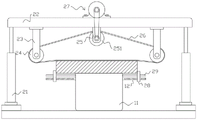
Fig. 1 is a schematic view of an overall structure provided by an embodiment of the present invention;
fig. 2 is a schematic structural diagram of an overall working state provided by the embodiment of the present invention;
fig. 3 is a schematic structural view of a first driving portion according to an embodiment of the present invention.
In the figure: 11. a platform; 12. a threaded rod; 13. positioning seats; 14. a limiting block; 15. a first gear; 16. a substrate; 17. a first motor; 18. a drive shaft; 19. a second gear; 21. a hydraulic cylinder; 22. mounting a plate; 23. a first bracket; 24. a driven roller; 25. a second bracket; 251. a drive roll; 26. polishing the belt; 27. a second driving section; 271. a second motor; 272. a pulley; 273. a belt; 28. a clamping block; 29. a slide bar.
Detailed Description
In order to make the objects, technical solutions and advantages of the embodiments of the present disclosure more apparent, the technical solutions of the embodiments of the present disclosure will be described clearly and completely with reference to the drawings of the embodiments of the present disclosure. It is to be understood that the described embodiments are only a few embodiments of the present disclosure, and not all embodiments. All other embodiments, which can be derived by a person skilled in the art from the described embodiments of the disclosure without any inventive step, are within the scope of protection of the disclosure.
Unless otherwise defined, technical or scientific terms used herein shall have the ordinary meaning as understood by one of ordinary skill in the art to which this disclosure belongs. The use of the word "comprising" or "comprises", and the like, in this disclosure is intended to mean that the elements or items listed before that word, include the elements or items listed after that word, and their equivalents, without excluding other elements or items. The terms "connected" and "coupled" and the like are not restricted to physical or mechanical connections, but may also include electrical connections, whether direct or indirect. "upper", "lower", "left", "right", and the like are used only to indicate relative positional relationships, and when the absolute position of the object being described is changed, the relative positional relationships may also be changed accordingly.
Referring to fig. 1-3, the present invention provides a technical solution: an aluminum product processing grinding device includes:
the clamping assembly comprises a clamping part and a clamping part, wherein the clamping part comprises a platform 11, a threaded rod 12, clamping blocks 28 and a first driving part, the threaded rod 12 is rotatably connected onto the platform 11, two sections of external threads with opposite directions are arranged on the threaded rod 12, the two clamping blocks 28 are respectively in threaded connection with two ends of the threaded rod 12, when the threaded rod 12 rotates, the clamping blocks 28 are acted by a threaded force and can move along the axial direction of the threaded rod 12, and because the external threads are opposite in direction, the two clamping blocks 28 can simultaneously approach or keep away from each other, the first driving part is used for driving the threaded rod 12 to rotate, a sliding rod 29 is arranged on the platform 11, one end of the sliding rod 29 is inserted into the clamping blocks 28, and through the arrangement of the sliding rod 29, the clamping blocks 28 can be positioned, so that the clamping blocks can only move along the axial direction of the threaded rod 12;
the polishing assembly comprises a hydraulic cylinder 21, a mounting plate 22, a first bracket 23, a second bracket 25, a driven roller 24, a driving roller 251 and a polishing belt 26, wherein a piston rod of the hydraulic cylinder 21 is fixedly mounted on the mounting plate 22, the height of the mounting plate 22 is controlled by the extension and retraction of the hydraulic cylinder 21, the first bracket 23 is fixedly mounted on the mounting plate 22, the driven roller 24 is rotatably connected to the first bracket 23, the second bracket 25 is fixedly mounted on the mounting plate 22, the driving roller 251 is rotatably connected to the second bracket 25, the polishing belt 26 is simultaneously sleeved outside the driven roller 24 and the driving roller 251, the polishing belt 26 is positioned at two sides of the platform 11, the mounting plate 22 descends to drive the polishing belt 26 to be close to the platform 11, the polishing belt 26 can be driven to rotate by the rotation of the driving roller 251, the polishing belt 26 can be polished by the contact of the aluminum plate, a second driving part 27 for driving the rotation of the driving roller 251 is arranged on the mounting plate 22, the driving of the second driving portion 27 may be provided to rotate the driving roller 251.
Please look up fig. 1, the inside of platform 11 is provided with positioning seat 13, and threaded rod 12 rotates to be connected on positioning seat 13, can fix a position threaded rod 12 through positioning seat 13, guarantees the stability of threaded rod 12 when rotatory, is provided with stopper 14 on threaded rod 12, and one side laminating of stopper 14 is on positioning seat 13, through stopper 14's setting, can guarantee that threaded rod 12 can only rotate, and can not carry out the displacement of other modes.
Please refer to fig. 1, the first driving portion includes a first gear 15, a second gear 19, a substrate 16 and a first motor 17, the first gear 15 is fixedly installed on the threaded rod 12, the substrate 16 is fixedly installed inside the platform 11, a transmission shaft 18 is disposed on an output shaft of the first motor 17, the second gear 19 is fixedly installed on the transmission shaft 18, the first gear 15 and the second gear 19 are engaged with each other, the transmission shaft 18 can be driven to rotate by the first motor 17, the transmission shaft 18 can drive the second gear 19 to rotate when rotating, the second gear 19 can drive the first gear 15 to rotate when rotating, so that the first gear 15 can drive the threaded rod 12 to rotate, the substrate 16 can position the transmission shaft 18, so as to increase the stability of the rotation, and both the first gear 15 and the second gear 19 are helical gears.
Referring to fig. 1 and 3, the second driving portion 27 includes a second motor 271, belt pulleys 272 and a belt 273, the second motor 271 is fixedly installed on the mounting plate 22, the two belt pulleys 272 are respectively installed on the output shaft of the second motor 271 and the driving roller 251, the belt 273 is simultaneously sleeved on the two belt pulleys 272, the belt pulleys 272 are respectively installed on the output shaft of the second motor 271 and the driving roller 251, and the two belt pulleys 272 are connected by the belt 273, so that the driving roller 251 can be driven to rotate when the second motor 271 rotates, and the polishing belt 26 can be driven to rotate.
Certain exemplary embodiments of the present invention have been described above by way of illustration only, and it will be apparent to those of ordinary skill in the art that the described embodiments may be modified in various different ways without departing from the spirit and scope of the present invention. Accordingly, the drawings and description are illustrative in nature and should not be construed as limiting the scope of the invention.
Claims (6)
1. The utility model provides an aluminum product processing grinding device which characterized in that includes:
the clamping assembly comprises a platform (11), a threaded rod (12), clamping blocks (28) and a first driving part, wherein the threaded rod (12) is rotatably connected to the platform (11), two sections of external threads in opposite directions are arranged on the threaded rod (12), the two clamping blocks (28) are respectively in threaded connection with two ends of the threaded rod (12), the first driving part is used for driving the threaded rod (12) to rotate, a sliding rod (29) is arranged on the platform (11), and one end of the sliding rod (29) is inserted into the clamping blocks (28);
a grinding component which comprises a hydraulic cylinder (21), a mounting plate (22), a first bracket (23), a second bracket (25), a driven roller (24), a driving roller (251) and a grinding belt (26), a piston rod of the hydraulic cylinder (21) is fixedly arranged on the mounting plate (22), the first bracket (23) is fixedly arranged on the mounting plate (22), the driven roller (24) is rotationally connected to the first bracket (23), the second bracket (25) is fixedly arranged on the mounting plate (22), the driving roller (251) is rotationally connected to the second bracket (25), the grinding belt (26) is sleeved outside the driven roller (24) and the driving roller (251) at the same time, the mounting plate (22) is provided with a second driving part (27) for driving the driving roller (251) to rotate.
2. An aluminum material working grinding apparatus as set forth in claim 1, wherein: the inner part of the platform (11) is provided with a positioning seat (13), and the threaded rod (12) is rotatably connected to the positioning seat (13).
3. An aluminum product processing grinding device as set forth in claim 2, characterized in that: the threaded rod (12) is provided with a limiting block (14), and one side of the limiting block (14) is attached to the positioning seat (13).
4. An aluminum material working grinding apparatus as set forth in claim 1, wherein: the first driving part comprises a first gear (15), a second gear (19), a base plate (16) and a first motor (17), the first gear (15) is fixedly installed on the threaded rod (12), and the base plate (16) is fixedly installed inside the platform (11).
5. An aluminum material working grinding apparatus as set forth in claim 4, wherein: a transmission shaft (18) is arranged on an output shaft of the first motor (17), the second gear (19) is fixedly installed on the transmission shaft (18), and the first gear (15) and the second gear (19) are meshed with each other.
6. An aluminum material working grinding apparatus as set forth in claim 1, wherein: the second driving part (27) comprises a second motor (271), belt wheels (272) and a belt (273), the second motor (271) is fixedly installed on the installation plate (22), the two belt wheels (272) are respectively installed on an output shaft of the second motor (271) and the driving roller (251), and the belt (273) is sleeved on the two belt wheels (272) at the same time.
Priority Applications (1)
| Application Number | Priority Date | Filing Date | Title |
|---|---|---|---|
| CN202220803412.9U CN217291808U (en) | 2022-04-08 | 2022-04-08 | Aluminum product processing grinding device |
Applications Claiming Priority (1)
| Application Number | Priority Date | Filing Date | Title |
|---|---|---|---|
| CN202220803412.9U CN217291808U (en) | 2022-04-08 | 2022-04-08 | Aluminum product processing grinding device |
Publications (1)
| Publication Number | Publication Date |
|---|---|
| CN217291808U true CN217291808U (en) | 2022-08-26 |
Family
ID=82937310
Family Applications (1)
| Application Number | Title | Priority Date | Filing Date |
|---|---|---|---|
| CN202220803412.9U Active CN217291808U (en) | 2022-04-08 | 2022-04-08 | Aluminum product processing grinding device |
Country Status (1)
| Country | Link |
|---|---|
| CN (1) | CN217291808U (en) |
-
2022
- 2022-04-08 CN CN202220803412.9U patent/CN217291808U/en active Active
Similar Documents
| Publication | Publication Date | Title |
|---|---|---|
| CN215036218U (en) | Stainless steel parts machining is with equipment of polishing convenient to adjust | |
| CN111300267B (en) | Multifunctional clamp for machining | |
| CN112355349A (en) | Machining device for multi-station forklift wheels | |
| CN111975379A (en) | High-efficient aluminum alloy rod processing equipment | |
| CN217291808U (en) | Aluminum product processing grinding device | |
| CN211760551U (en) | Grinding device is used in automobile parts processing | |
| CN219485450U (en) | Multifunctional clamp for magnetic material production and processing | |
| CN218592519U (en) | Grinding device convenient to height-adjusting | |
| CN116690258A (en) | Manufacturing device and process for machining high-torque universal joint fork | |
| CN217890472U (en) | Burr removing device based on mechanical automation | |
| CN216859012U (en) | Clamp for numerical control machining | |
| CN214771184U (en) | Translation phosphorus removal device for mechanical phosphorus removal | |
| CN214642029U (en) | Clamp for piston ring machining | |
| CN211027733U (en) | Quick and efficient punching device for processing building curtain wall aluminum profile stand column | |
| CN115070588A (en) | High-precision automatic polishing equipment | |
| CN210189116U (en) | Gear sleeve machining device | |
| CN219526796U (en) | High-speed laser cladding equipment | |
| CN212762540U (en) | Surface grinding device for aluminum plate machining | |
| CN219005340U (en) | Vertical machining center fixture of numerical control machine tool | |
| CN213380276U (en) | Main sliding table unit of gantry vertical numerical control milling machine machining center | |
| CN219094042U (en) | Laser cutting clamp | |
| CN219094649U (en) | Metal part processing grinding device | |
| CN220144860U (en) | Novel cutting equipment | |
| CN220427540U (en) | Milling machine processing auxiliary support clamp | |
| CN219005843U (en) | Positioning fixture of two-way centre gripping |
Legal Events
| Date | Code | Title | Description |
|---|---|---|---|
| GR01 | Patent grant | ||
| GR01 | Patent grant |