CN217211481U - Pathological section cutter with wax chip anti-splashing structure - Google Patents
Pathological section cutter with wax chip anti-splashing structure Download PDFInfo
- Publication number
- CN217211481U CN217211481U CN202123401437.0U CN202123401437U CN217211481U CN 217211481 U CN217211481 U CN 217211481U CN 202123401437 U CN202123401437 U CN 202123401437U CN 217211481 U CN217211481 U CN 217211481U
- Authority
- CN
- China
- Prior art keywords
- pass
- pivot
- seat
- wax
- pathological
- Prior art date
- Legal status (The legal status is an assumption and is not a legal conclusion. Google has not performed a legal analysis and makes no representation as to the accuracy of the status listed.)
- Active
Links
Images


Classifications
-
- Y—GENERAL TAGGING OF NEW TECHNOLOGICAL DEVELOPMENTS; GENERAL TAGGING OF CROSS-SECTIONAL TECHNOLOGIES SPANNING OVER SEVERAL SECTIONS OF THE IPC; TECHNICAL SUBJECTS COVERED BY FORMER USPC CROSS-REFERENCE ART COLLECTIONS [XRACs] AND DIGESTS
- Y02—TECHNOLOGIES OR APPLICATIONS FOR MITIGATION OR ADAPTATION AGAINST CLIMATE CHANGE
- Y02P—CLIMATE CHANGE MITIGATION TECHNOLOGIES IN THE PRODUCTION OR PROCESSING OF GOODS
- Y02P70/00—Climate change mitigation technologies in the production process for final industrial or consumer products
- Y02P70/10—Greenhouse gas [GHG] capture, material saving, heat recovery or other energy efficient measures, e.g. motor control, characterised by manufacturing processes, e.g. for rolling metal or metal working
Abstract
The utility model belongs to the pathological section machine field specifically is a pathological section machine with wax bits prevent splash structure, including pathology fixture, removal slice mechanism, be convenient for produce the wax bits to the section and shelter from the mechanism that splashes that prevents that retrieves from different angles, pathology fixture one side is provided with prevent splash mechanism, prevent that splash mechanism inboard is provided with remove slice mechanism, prevent that splash mechanism includes collection box, fixing base, pivot, rotating electrical machines, cassette, protection casing, receiver, suction fan. Through the utility model discloses a prevent mechanism that splashes drives pivot and protection casing through starting rotating electrical machines and carries out rotary motion, and the convenience shelters from pathological section machine in cutting process from different position rotation protection casing angles, prevents the condition that the wax bits splashes, and the effect of receiver and suction fan is being deuterogamied, retrieves the clearance to cutting back wax bits, reduces personnel's operation, improves work efficiency.
Description
Technical Field
The utility model belongs to the pathological section machine field specifically relates to a pathological section machine with wax bits prevent splash structure.
Background
Pathological section is prepared by taking pathological tissues of a certain size, making pathological section by histopathology method (usually, the pathological tissues are embedded in paraffin block, cut into thin slices by a microtome, and stained with hematoxylin-eosin (H-E)), and further examining the pathological section by microscope. Present pathological section machine in market is adding man-hour, because pathological paraffin section can produce a lot of wax bits and splash each position, influences equipment normal operating very easily, often needs the staff constantly to clear up with the brush to lead to the section time long, work efficiency is low.
SUMMERY OF THE UTILITY MODEL
An object of the utility model is to provide a pathological section machine with structure of splashing is prevented to wax bits.
The utility model discloses the technical scheme who adopts as follows:
the utility model provides a pathology slicer with wax bits prevent splash structure, includes pathology fixture, removes the slicing mechanism, is convenient for produce the mechanism that splashes that prevents that wax bits shelter from and retrieve from different angles to the section, pathology fixture one side is provided with prevent splash mechanism, prevent that splash mechanism inboard is provided with remove slicing mechanism, prevent splash mechanism including collection box, fixing base, pivot, rotating electrical machines, cassette, protection casing, receiver, suction fan, the collection box outside is provided with the fixing base, the fixing base inboard is provided with the pivot, pivot one side is provided with the rotating electrical machines, the pivot outside is provided with the cassette, the cassette inboard is provided with the protection casing, the protection casing below is provided with the receiver, receiver one side is provided with the suction fan.
Preferably: pathological clamping mechanism includes slicer body, adjustment tank, regulation seat, paraffin grip slipper, handle, slicer body one side is provided with the adjustment tank, adjustment tank one side is provided with the regulation seat, regulation seat one side is provided with the paraffin grip slipper, slicer body front side is provided with the handle.
Preferably: the adjusting groove is formed in the inner side of the slicing machine body, the adjusting groove is connected with the adjusting seat in a sliding mode, the adjusting seat is connected with the paraffin clamping seat through bolts, and the slicing machine body is connected with the handle through a bearing.
So set up, make things convenient for the dismouting to change adjust the seat paraffin grip slipper maintains.
Preferably: the movable slicing mechanism comprises a sliding groove, a screw rod, a movable motor, a movable seat, a knife rest base, a knife pressing plate and an adjusting bolt, wherein the screw rod is arranged on the inner side of the sliding groove, the movable motor is arranged on one side of the screw rod, the movable seat is arranged above the sliding groove, the knife rest base is arranged above the movable seat, the knife pressing plate is arranged above the knife rest base, and the adjusting bolt is arranged on the outer side of the knife pressing plate.
Preferably: the sliding groove is connected with the screw rod through a bearing, the screw rod is connected with the movable motor in a key connection mode, the sliding groove is connected with the movable seat in a sliding mode, the movable seat is connected with the tool rest base through a bolt, the tool rest base is connected with the tool pressing plate through a bolt, and the tool pressing plate is connected with the adjusting bolt through a thread.
So set up, the bearing is connected and is convenient for the screw rod is nimble to be rotated, makes things convenient for the dismouting to change the pressure cutting board adjusting bolt maintains.
Preferably: the recycling bin with the fixing base passes through welded connection, the fixing base with the pivot passes through the bearing and connects, the pivot with the rotating electrical machines key-type connection, the pivot with the cassette passes through welded connection, the cassette with the protection casing passes through bolted connection, the recycling bin with the receiver passes through bolted connection, the receiver with the suction fan passes through bolted connection.
So set up, the bearing is connected and is convenient for the pivot is nimble to be rotated, makes things convenient for the dismouting to change the protection casing receiver the suction fan maintains.
In the structure, firstly, a technician clamps a wax block in the paraffin clamping seat, utilizes the adjusting groove to lift and move the position of the adjusting seat to adjust the distance between the paraffin clamping seat and the cutter pressing plate, starts the moving motor to drive the screw rod to rotate, so that the moving seat drives the cutter frame base to move the position to be sliced, then controls the angle of the blade on the cutter pressing plate to process by using the adjusting bolt, generates wax scraps in the slicing process, drives the rotating shaft and the protective cover to rotate by starting the rotating motor, is convenient to rotate at different positions to shield the protective cover angle in the cutting process, prevents the wax scraps from splashing, and is matched with the effects of the storage box and the suction fan which are arranged at the two sides of the recovery box to collect and clean the cut wax scraps so as to reduce the operation of the technician, the working efficiency is improved.
The utility model has the advantages that: adopt and prevent the mechanism that splashes, drive pivot and protection casing through starting rotating electrical machines and carry out rotary motion, conveniently shelter from pathological section machine at the cutting in-process from different position rotation protection casing angles, prevent the condition that the wax bits splashes, the effect of deuterogamying receiver and suction fan, retrieves the clearance to cutting back wax bits, and the reduction personnel operate, improves work efficiency.
Drawings
The accompanying drawings, which are included to provide a further understanding of the invention and are incorporated in and constitute a part of this specification, illustrate embodiments of the invention and together with the description serve to explain the principles of the invention. In the drawings:
fig. 1 is a schematic front view of a pathological section cutter with a wax chip splash-proof structure according to the present invention;
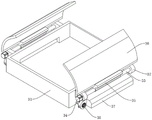
fig. 2 is a schematic perspective view of a pathological section cutter with a wax chip splash-proof structure according to the present invention;
fig. 3 is a schematic view of a pathological clamping mechanism of a pathological microtome with a wax chip splash-proof structure according to the present invention;
fig. 4 is a schematic view of a moving slicing mechanism of a pathological section machine with a wax chip splash-proof structure according to the present invention;
fig. 5 is a schematic view of the splash-proof mechanism of the pathological section machine with the splash-proof structure for wax scraps.
The reference numerals are explained below:
1. a pathology gripping mechanism; 2. a mobile slicing mechanism; 3. an anti-splash mechanism; 11. a slicer body; 12. an adjustment groove; 13. an adjusting seat; 14. a paraffin wax clamping seat; 15. a handle; 21. a chute; 22. a screw; 23. a moving motor; 24. a movable seat; 25. a tool holder base; 26. pressing a cutter plate; 27. adjusting the bolt; 31. a recycling bin; 32. a fixed seat; 33. a rotating shaft; 34. a rotating electric machine; 35. a card holder; 36. a protective cover; 37. a storage box; 38. a suction fan.
Detailed Description
The present invention will be further described with reference to the following examples and drawings.
As shown in figures 1, 2, 3, 4 and 5, the pathological section cutter with the wax chip anti-splashing structure comprises a pathological clamping mechanism 1 and a movable section cutting mechanism 2, the anti-splashing mechanism 3 is convenient for shielding and recovering wax chips generated by a section from different angles, the anti-splashing mechanism 3 is arranged on one side of the pathological clamping mechanism 1, the movable section cutting mechanism 2 is arranged on the inner side of the anti-splashing mechanism 3, the pathological clamping mechanism 1 comprises a section cutter body 11, an adjusting groove 12, an adjusting seat 13, a paraffin clamping seat 14 and a handle 15, the adjusting groove 12 is arranged on one side of the section cutter body 11, the adjusting seat 13 is arranged on one side of the adjusting groove 12, the paraffin clamping seat 14 is arranged on one side of the adjusting seat 13, the handle 15 is arranged on the front side of the section cutter body 11, the movable section cutting mechanism 2 comprises a sliding groove 21, a screw 22, a movable motor 23, a movable seat 24, a cutter rest base 25, a cutter pressing plate 26, Adjusting bolt 27, spout 21 inboard is provided with screw rod 22, screw rod 22 one side is provided with moving motor 23, spout 21 top is provided with removes seat 24, it is provided with knife rest base 25 to remove seat 24 top, knife rest base 25 top is provided with cutting board 26, the cutting board 26 outside is provided with adjusting bolt 27, prevent that mechanism 3 that splashes includes collection box 31, fixing base 32, pivot 33, rotating electrical machines 34, cassette 35, protection casing 36, receiver 37, suction fan 38, the collection box 31 outside is provided with fixing base 32, fixing base 32 inboard is provided with pivot 33, pivot 33 one side is provided with rotating electrical machines 34, the pivot 33 outside is provided with cassette 35, cassette 35 inboard is provided with protection casing 36, protection casing 36 below is provided with receiver 37, receiver 37 one side is provided with suction fan 38.
Preferably: the adjusting groove 12 is formed in the inner side of the slicer body 11, the adjusting groove 12 is connected with the adjusting seat 13 in a sliding mode, the adjusting seat 13 is connected with the paraffin clamping seat 14 through bolts, and the slicer body 11 is connected with the handle 15 through a bearing; the sliding chute 21 is connected with the screw rod 22 through a bearing, the screw rod 22 is connected with the movable motor 23 in a key mode, the sliding chute 21 is connected with the movable seat 24 in a sliding mode, the movable seat 24 is connected with the tool rest base 25 through a bolt, the tool rest base 25 is connected with the tool pressing plate 26 through a bolt, and the tool pressing plate 26 is connected with the adjusting bolt 27 through a thread; recycling bin 31 passes through welded connection with fixing base 32, and fixing base 32 passes through the bearing with pivot 33 and is connected, pivot 33 and 34 key-type connections of rotating electrical machines, and pivot 33 passes through welded connection with cassette 35, and cassette 35 passes through bolted connection with protection casing 36, and recycling bin 31 passes through bolted connection with receiver 37, and receiver 37 passes through bolted connection with suction fan 38.
The working principle is as follows: firstly, a technician clamps a wax block in a paraffin clamping seat 14, utilizes a position of an adjusting groove 12 to lift and move an adjusting seat 13 to adjust the distance between the paraffin clamping seat 14 and a knife pressing plate 26, starts a moving motor 23 to drive a screw rod 22 to rotate, so that a moving seat 24 drives a knife rest base 25 to move a position needing to be sliced, then controls the angle of a blade on the knife pressing plate 26 by using an adjusting bolt 27 to process, generates wax scraps in the slicing process, drives a rotating shaft 33 and a protective cover 36 to rotate by starting a rotating motor 34, is convenient to shield the blade from different positions by rotating the protective cover 36 in the cutting process, prevents the wax scraps from splashing, and is matched with the effects of a storage box 37 and a suction fan 38 which are arranged at two sides of a recovery box 31 to collect and clean the cut wax scraps, so that the operation of the technician is reduced, and the working efficiency is improved.
The preferred embodiments of the present invention have been described in detail with reference to the accompanying drawings, but the present invention is not limited to the above embodiments, and various changes can be made without departing from the gist of the present invention within the knowledge of those skilled in the art.
Claims (6)
1. The utility model provides a pathology slicer with splash structure is prevented to wax bits, includes pathology fixture (1), removes section mechanism (2), its characterized in that: the anti-splashing mechanism (3) is convenient for shielding and recovering wax scraps generated by slicing from different angles, the anti-splashing mechanism (3) is arranged on one side of the pathological clamping mechanism (1), and the movable slicing mechanism (2) is arranged on the inner side of the anti-splashing mechanism (3);
prevent mechanism of splashing (3) including collection box (31), fixing base (32), pivot (33), rotating electrical machines (34), cassette (35), protection casing (36), receiver (37), suction fan (38), collection box (31) outside is provided with fixing base (32), fixing base (32) inboard is provided with pivot (33), pivot (33) one side is provided with rotating electrical machines (34), the pivot (33) outside is provided with cassette (35), cassette (35) inboard is provided with protection casing (36), protection casing (36) below is provided with receiver (37), receiver (37) one side is provided with suction fan (38).
2. The pathological microtome having a wax chip splash guard structure as defined in claim 1, wherein: pathological clamping mechanism (1) is including slicer body (11), adjustment tank (12), regulation seat (13), paraffin grip slipper (14), handle (15), slicer body (11) one side is provided with adjustment tank (12), adjustment tank (12) one side is provided with regulation seat (13), regulation seat (13) one side is provided with paraffin grip slipper (14), slicer body (11) front side is provided with handle (15).
3. The pathological microtome with a wax chip splash prevention structure as claimed in claim 2, wherein: the shaping of adjustment tank (12) is in slicer body (11) are inboard, adjustment tank (12) with adjust seat (13) sliding connection, adjust seat (13) with paraffin grip slipper (14) pass through bolted connection, slicer body (11) with handle (15) pass through the bearing and connect.
4. The pathological microtome with a wax chip splash guard according to claim 1, wherein: remove slicer mechanism (2) and include spout (21), screw rod (22), moving motor (23), remove seat (24), knife rest base (25), pressure knife board (26), adjusting bolt (27), spout (21) inboard is provided with screw rod (22), screw rod (22) one side is provided with moving motor (23), spout (21) top is provided with remove seat (24), it is provided with to remove seat (24) top knife rest base (25), knife rest base (25) top is provided with pressure knife board (26), the pressure knife board (26) outside is provided with adjusting bolt (27).
5. The pathological microtome according to claim 4, wherein the wax chip splash guard is configured to: spout (21) with screw rod (22) pass through the bearing and connect, screw rod (22) with remove motor (23) key-type connection, spout (21) with remove seat (24) sliding connection, remove seat (24) with knife rest base (25) pass through bolted connection, knife rest base (25) with pressure cutting board (26) pass through bolted connection, pressure cutting board (26) with adjusting bolt (27) pass through threaded connection.
6. The pathological microtome with a wax chip splash guard according to claim 1, wherein: recovery box (31) with fixing base (32) pass through welded connection, fixing base (32) with pivot (33) pass through the bearing and connect, pivot (33) with rotating electrical machines (34) key-type connection, pivot (33) with welded connection is passed through in cassette (35), cassette (35) with protection casing (36) pass through bolted connection, recovery box (31) with receiver (37) pass through bolted connection, receiver (37) with suction fan (38) pass through bolted connection.
Priority Applications (1)
| Application Number | Priority Date | Filing Date | Title |
|---|---|---|---|
| CN202123401437.0U CN217211481U (en) | 2021-12-30 | 2021-12-30 | Pathological section cutter with wax chip anti-splashing structure |
Applications Claiming Priority (1)
| Application Number | Priority Date | Filing Date | Title |
|---|---|---|---|
| CN202123401437.0U CN217211481U (en) | 2021-12-30 | 2021-12-30 | Pathological section cutter with wax chip anti-splashing structure |
Publications (1)
| Publication Number | Publication Date |
|---|---|
| CN217211481U true CN217211481U (en) | 2022-08-16 |
Family
ID=82787981
Family Applications (1)
| Application Number | Title | Priority Date | Filing Date |
|---|---|---|---|
| CN202123401437.0U Active CN217211481U (en) | 2021-12-30 | 2021-12-30 | Pathological section cutter with wax chip anti-splashing structure |
Country Status (1)
| Country | Link |
|---|---|
| CN (1) | CN217211481U (en) |
Cited By (2)
| Publication number | Priority date | Publication date | Assignee | Title |
|---|---|---|---|---|
| CN115213728A (en) * | 2022-08-24 | 2022-10-21 | 余江县恒欣精密元件有限公司 | Metal tailstock processing is with repairing type equipment |
| CN116448479A (en) * | 2023-04-14 | 2023-07-18 | 中国人民解放军总医院第三医学中心 | Automatic slicing device for general sampling of pathology biopsy |
-
2021
- 2021-12-30 CN CN202123401437.0U patent/CN217211481U/en active Active
Cited By (4)
| Publication number | Priority date | Publication date | Assignee | Title |
|---|---|---|---|---|
| CN115213728A (en) * | 2022-08-24 | 2022-10-21 | 余江县恒欣精密元件有限公司 | Metal tailstock processing is with repairing type equipment |
| CN115213728B (en) * | 2022-08-24 | 2023-10-31 | 余江县恒欣精密元件有限公司 | Repair equipment for metal tailstock machining |
| CN116448479A (en) * | 2023-04-14 | 2023-07-18 | 中国人民解放军总医院第三医学中心 | Automatic slicing device for general sampling of pathology biopsy |
| CN116448479B (en) * | 2023-04-14 | 2024-01-16 | 中国人民解放军总医院第三医学中心 | Automatic slicing device for general sampling of pathology biopsy |
Similar Documents
| Publication | Publication Date | Title |
|---|---|---|
| CN217211481U (en) | Pathological section cutter with wax chip anti-splashing structure | |
| CN210818710U (en) | Machining device with function is collected to sweeps | |
| CN211804186U (en) | Copper bar cutting device | |
| CN214640577U (en) | Efficient semi-automatic cutting machine device | |
| CN216097794U (en) | Combined lathe | |
| CN214557929U (en) | Double-station tool for machining outer edge of brake | |
| CN213135911U (en) | Cnc engraving and milling machine with dust removal function | |
| CN213858301U (en) | Chip breaking device capable of achieving reciprocating cutting and adjustable in distance | |
| CN211729544U (en) | Multifunctional electric tool for woodworker | |
| CN112439950A (en) | Double-station tool for machining outer edge of brake and machining method of double-station tool | |
| CN216551037U (en) | Beat limit machine equipment convenient to collect crushed aggregates | |
| CN219444570U (en) | Adjustable trimming machine | |
| CN220679522U (en) | Edge cutter for metal products | |
| CN220806305U (en) | Gong sword processing equipment | |
| CN214602291U (en) | Saw blade gear grinding machine | |
| CN217619463U (en) | A edge of a knife processing apparatus for carbide cutting tool processing | |
| CN219503816U (en) | Cutting machine | |
| CN217121979U (en) | Long service life's cutter | |
| CN217776401U (en) | Lathe pushes down structure | |
| CN211052700U (en) | Aluminum alloy template multi-angle cutting device with piece clearance function | |
| CN219561650U (en) | Cutting device | |
| CN218873959U (en) | Cutting device for machining numerical control tool | |
| CN216831357U (en) | Precise sliding table saw with debris collection function and convenient to clean | |
| CN219648784U (en) | Milling machine for processing edge die | |
| CN213560109U (en) | Punching equipment for hardware machining |
Legal Events
| Date | Code | Title | Description |
|---|---|---|---|
| GR01 | Patent grant | ||
| GR01 | Patent grant |