CN217166996U - Novel decorative paper cutting device - Google Patents
Novel decorative paper cutting device Download PDFInfo
- Publication number
- CN217166996U CN217166996U CN202220024529.7U CN202220024529U CN217166996U CN 217166996 U CN217166996 U CN 217166996U CN 202220024529 U CN202220024529 U CN 202220024529U CN 217166996 U CN217166996 U CN 217166996U
- Authority
- CN
- China
- Prior art keywords
- fixedly connected
- decorative paper
- cutting device
- frame
- plate
- Prior art date
- Legal status (The legal status is an assumption and is not a legal conclusion. Google has not performed a legal analysis and makes no representation as to the accuracy of the status listed.)
- Active
Links
Images


Abstract
The utility model discloses a novel decorative paper cutting device, which comprises a frame, the top of frame is equipped with the installing port, fixedly connected with fretwork piece in the installing port, two risers of the bottom inner wall fixedly connected with of frame, fixedly connected with inclined frame between two risers, fixedly connected with fine mesh in the inclined frame, inclined frame slope setting at the top of two risers, two fixedly connected with connecting strip between the riser, the bottom fixedly connected with fan of connecting strip, two C templates of top fixedly connected with of fretwork piece, the top of C template is pegged graft and is had L form board, the equal fixedly connected with connecting block in both ends of L form board, and the connecting block top is run through to peg graft and is had the bracing piece. The utility model discloses can handle the wastepaper in time, improve the effect of cutting, can also press from both sides the decorative paper that needs the cutting tightly, prevent that the in-process of cutting from taking place the phenomenon of decorative paper slope to in order to avoid causing the cutting error.
Description
Technical Field
The utility model relates to a decorative paper cutting technical field especially relates to a novel decorative paper cutting device.
Background
Decorative paper is essential raw materials among many building materials products, low clamp plate, high-pressure board that furniture, cupboard were used, PLASTIC LAMINATED, floor etc. in addition, decorative paper is put below top layer paper in product structure, mainly plays the decorative effect that provides the decorative pattern and prevents the covering effect that bottom glue solution oozes appearing, for the convenience of the use in later stage, need utilize cutting device with the different standard sizes of decorative paper cutting.
At present, most of the existing decorative paper cutting devices have the following defects: in the decorative paper cutting process, the wastepaper that its cutting produced can not in time be cleared up for the wastepaper easily covers on the decorative paper, influences the cutting effect of decorative paper, and to sum up, current speed reduction casing decorative paper cutting device still can not agree with actual need well mostly.
SUMMERY OF THE UTILITY MODEL
The utility model aims at solving the defects existing in the prior art and providing a novel decorative paper cutting device.
In order to realize the purpose, the utility model adopts the following technical scheme:
the utility model provides a novel decorative paper cutting device, includes the frame, the top of frame is equipped with the installing port, fixedly connected with fretwork piece in the installing port, two risers of the bottom inner wall fixedly connected with of frame, the oblique frame of fixedly connected with between two risers, the thin net of fixedly connected with in the frame to one side, the oblique frame is in the top slope setting of two risers, two fixedly connected with connecting strip between the riser, the bottom fixedly connected with fan of connecting strip.
Further, two C templates of top fixedly connected with of fretwork piece, the top of C template is pegged graft and is had L form board, the equal fixedly connected with connecting block in both ends of L form board, and the grafting has the bracing piece at the connecting block top is run through, and the outer wall of bracing piece has cup jointed the spring, the bottom of bracing piece and the top fixed connection of C template.
Furthermore, one side of the L-shaped plate is rotatably connected with a rotating clamping plate, one side of the C-shaped plate is fixedly connected with a clamping strip, and the clamping strip is clamped with the rotating clamping plate.
Furthermore, the outer wall of bracing piece has cup jointed the spacing ring, and the spacing ring is located the top of connecting block.
Furthermore, a plurality of supporting blocks are fixedly connected to the top of the rack, a guide rod is fixedly connected between the two supporting blocks, a sliding block is connected to the outer wall of the guide rod in a sliding mode, a connecting plate is fixedly connected between the two sliding blocks, two land wheels are fixedly connected to the bottom of the connecting plate, and the land wheels roll at the top of the hollow block.
Furthermore, the top of frame fixedly connected with backup pad, one side fixedly connected with electric putter of backup pad, one end of electric putter passes one side fixed connection of backup pad and connecting plate.
Furthermore, the other side of the connecting plate is fixedly connected with a rodless cylinder, and one side of the rodless cylinder is provided with a laser.
Furthermore, the top of frame fixedly connected with control module, control module and laser instrument, fan, electric putter and rodless cylinder electric connection.
Further, the top fixedly connected with spacing of fretwork piece, spacing be located the one end of two C templates, the equal fixedly connected with blend stop in both sides at bevel connection top, the equal fixedly connected with guard plate in both sides of frame.
The beneficial effects of the utility model are that:
1. the utility model discloses a make the wastepaper that produces when cutting to fall through the fretwork piece and collect on the fine net under the suction effect of fan to can handle the wastepaper in time, improve the effect of cutting.
2. The utility model discloses a C template, L form board, rotation cardboard and the cooperation setting of calorie of strip can press from both sides the decorative paper that needs the cutting tight, prevent that the in-process of cutting from taking place the phenomenon of decorative paper slope to cause the cutting error.
3. The utility model discloses an electric putter drives the land wheel and rolls on the fretwork piece to drive the laser instrument and remove, thereby cut decorative paper, labour saving and time saving, simultaneously, the sliding block slides on the guide bar and leads to the direction of cutting, improves the stability of cutting.
4. The utility model discloses a position of placing of spacing to the decorative paper carries on spacingly to can make the decorative paper put, make things convenient for the cutting in later stage, the guard plate protects the staff, prevents that the staff from missing and bumps cutting device, in order to avoid causing the injury.
Drawings
Fig. 1 is a schematic structural view of a novel decorative paper cutting device in an embodiment 1 of the present invention;
Fig. 2 is a schematic right side perspective view of a novel decorative paper cutting device according to embodiment 1 of the present invention;
fig. 3 is a schematic left side perspective view of a novel decorative paper cutting device according to embodiment 1 of the present invention;
fig. 4 is a schematic view of a partial left-side three-dimensional structure of a novel decorative paper cutting device provided by the present invention in embodiment 1;
fig. 5 is a schematic view of a partial right side three-dimensional structure of a novel decorative paper cutting device according to embodiment 1 of the present invention;
fig. 6 is a schematic view of a three-dimensional structure of the novel decorative paper cutting device provided by the present invention in embodiment 2.
In the figure: 1. a frame; 2. hollowing out the block; 3. a laser; 4. a vertical plate; 5. an inclined frame; 6. a fine mesh; 7. a connecting strip; 8. a fan; 9. a support block; 10. a guide bar; 11. a slider; 12. a connecting plate; 13. a land wheel; 14. a support plate; 15. an electric push rod; 16. a control module; 17. a rodless cylinder; 18. c-shaped plates; 19. an L-shaped plate; 20. a support bar; 21. connecting blocks; 22. a limiting ring; 23. a spring; 24. clamping the strip; 25. rotating the clamping plate; 26. a limiting strip; 27. blocking strips; 28. and (4) a protective plate.
Detailed Description
The technical solutions in the embodiments of the present invention will be described clearly and completely with reference to the accompanying drawings in the embodiments of the present invention, and it is obvious that the described embodiments are only some embodiments of the present invention, not all embodiments.
Example 1
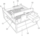
Referring to fig. 1-5, a novel decorative paper cutting device, which comprises a frame 1, the top of frame 1 is equipped with the installing port, there is fretwork piece 2 through the bolt fastening in the installing port, the bottom inner wall of frame 1 has two risers 4 through the bolt fastening, there is oblique frame 5 through the bolt fastening between two risers 4, there is thin net 6 through the bolt fastening in the oblique frame 5, the wastepaper can not pass through the mesh of thin net, only allow wind to pass, oblique frame 5 sets up at the top slope of two risers 4, there is connecting strip 7 through the bolt fastening between two risers 4, there is fan 8 bottom of connecting strip 7 through the bolt fastening, make the wastepaper fall through fretwork piece 2 and collect on thin net 6 under the suction of fan 8, thereby in time clear up the wastepaper.
The top of the hollowed-out block 2 is fixed with two C-shaped plates 18 through bolts, the top of each C-shaped plate 18 is inserted with an L-shaped plate 19, two ends of each L-shaped plate 19 are both fixed with connecting blocks 21 through bolts, the top of each connecting block 21 is penetrated and inserted with a supporting rod 20, the outer wall of each supporting rod 20 is sleeved with a spring 23, the springs 23 facilitate the resetting of the L-shaped plates 19, the bottom ends of the supporting rods 20 are fixedly connected with the top of the C-shaped plates 18, one side of each L-shaped plate 19 is rotatably connected with a rotating clamping plate 25, one side of each C-shaped plate 18 is fixed with a clamping strip 24 through bolts, the clamping strips 24 are clamped with the rotating clamping plates 25, the L-shaped plates 19 are pressed downwards to drive the connecting blocks 21 to slide on the supporting rods 20, so that the bottoms of the L-shaped plates 19 are in contact with decorative paper, the rotating clamping plates 25 are clamped on the clamping strips 24, the decorative paper is compressed, the outer walls of the supporting rods 20 are sleeved with limiting rings 22, and the limiting rings 22 are positioned above the connecting blocks 21, the limiting ring 22 prevents the L-shaped plate from completely separating from the C-shaped plate 18 when resetting, the top of the rack 1 is fixed with a plurality of supporting blocks 9 through bolts, a guide rod 10 is fixed between the two supporting blocks 9 through bolts, the outer wall of the guide rod 10 is connected with a sliding block 11 in a sliding manner, the sliding block 11 slides on the guide rod 10 to guide the cutting direction, a connecting plate 12 is fixed between the two sliding blocks 11 through bolts, two land wheels 13 are fixed at the bottom of the connecting plate 12 through bolts, the land wheels 13 roll on the top of the hollow block 2, a supporting plate 14 is fixed at the top of the rack 1 through bolts, an electric push rod 15 is fixed at one side of the supporting plate 14 through bolts, one end of the electric push rod 15 penetrates through the supporting plate 14 to be fixedly connected with one side of the connecting plate 12, the land wheels 13 roll on the hollow block 2 under the driving of the electric push rod 15, so as to drive the supporting plate 12 to move and cut the decorative paper, the other side of the connecting plate 12 is fixed with a rodless cylinder 17 through a bolt, a laser 3 is arranged on one side of the rodless cylinder 17, the laser 3 moves back and forth under the driving of the rodless cylinder 17 to adjust the cutting position, the top of the rack 1 is fixed with a control module 16 through a bolt, the control module 16 is electrically connected with the laser 3, the fan 8, the electric push rod 15 and the rodless cylinder 17, and the type of the laser 3 is Expert-II.
The working principle of the embodiment is as follows: when the laser cutting machine is used, firstly, decorative paper is placed at the top of the hollow block 2 and is positioned between the two C-shaped plates 18, then the L-shaped plate 19 is pressed downwards to drive the connecting block 21 to slide on the supporting rod 20, so that the bottom of the L-shaped plate 19 is contacted with the decorative paper, then the rotating clamping plate 25 is clamped on the clamping strip 24, so that the decorative paper is pressed tightly, then the control module 16 controls the electric push rod 15 to start, the land wheels 13 roll on the hollow block 2 under the driving of the electric push rod 15 to drive the supporting plate 12 to move, further the laser 3 is driven to move, the decorative paper is cut, the sliding block 11 is driven to slide on the guide rod 10 to guide the cutting direction, when the cutting position needs to be adjusted, the control module 16 controls the rodless cylinder 17 to start, the laser 3 moves back and forth under the driving of the rodless cylinder 17, and the cutting position is adjusted, meanwhile, the control module 16 controls the fan 8 to start, and paper scraps are made to fall onto the fine net 6 through the hollow blocks 2 to be collected under the action of suction of the fan 8, so that the paper scraps are cleaned in time.
Example 2
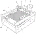
Referring to fig. 6, a novel decorative paper cutting device, there is spacing 26 at the top that still includes fretwork piece 2 through the bolt fastening, spacing 26 is spacing to the position of placing of decorative paper, so that decorative paper sets, spacing 26 is located the one end of two C template 18, the both sides at 5 tops of oblique frame all have blend stop 27 through the bolt fastening, blend stop 27 prevents that the wastepaper from falling beyond fine mesh 6, the both sides of frame 1 all have guard plate 28 through the bolt fastening, guard plate 28 protects the staff, prevent that the staff from missing and touch cutting device, in order to avoid causing the injury.
The working principle of the embodiment is as follows: during the use, spacing 26 is spacing to the position that decorative paper was placed, prevents that decorative paper from placing the slope, and guard plate 28 prevents that the staff from touching cutting device by mistake to cause the injury.
The above, only be the concrete implementation of the preferred embodiment of the present invention, but the protection scope of the present invention is not limited thereto, and any person skilled in the art is in the technical scope of the present invention, according to the technical solution of the present invention and the utility model, the concept of which is equivalent to replace or change, should be covered within the protection scope of the present invention.
Claims (9)
1. The utility model provides a novel decorative paper cutting device, includes frame (1), its characterized in that, the top of frame (1) is equipped with the installing port, fixedly connected with fretwork piece (2) in the installing port, two risers (4) of bottom inner wall fixedly connected with of frame (1), fixedly connected with inclined frame (5) between two risers (4), fixedly connected with fine mesh (6) in inclined frame (5), inclined frame (5) are in the top slope setting of two risers (4), two fixedly connected with connecting strip (7), bottom fixedly connected with fan (8) of connecting strip (7) between riser (4).
2. The novel decorative paper cutting device of claim 1, wherein two C-shaped plates (18) are fixedly connected to the top of the hollowed-out block (2), an L-shaped plate (19) is inserted into the top of each C-shaped plate (18), connecting blocks (21) are fixedly connected to both ends of each L-shaped plate (19), a supporting rod (20) is inserted into the top of each connecting block (21) in a penetrating manner, a spring (23) is sleeved on the outer wall of each supporting rod (20), and the bottom end of each supporting rod (20) is fixedly connected with the top of each C-shaped plate (18).
3. The novel decorative paper cutting device of claim 2, wherein one side of the L-shaped plate (19) is rotatably connected with a rotating clamping plate (25), one side of the C-shaped plate (18) is fixedly connected with a clamping strip (24), and the clamping strip (24) is clamped with the rotating clamping plate (25).
4. A novel decorative paper cutting device according to claim 2, characterized in that a limiting ring (22) is sleeved on the outer wall of the support rod (20), and the limiting ring (22) is positioned above the connecting block (21).
5. A novel decorative paper cutting device according to claim 1, characterized in that a plurality of supporting blocks (9) are fixedly connected to the top of the machine frame (1), a guide rod (10) is fixedly connected between two supporting blocks (9), a sliding block (11) is slidably connected to the outer wall of the guide rod (10), a connecting plate (12) is fixedly connected between two sliding blocks (11), two land wheels (13) are fixedly connected to the bottom of the connecting plate (12), and the land wheels (13) roll on the top of the hollow block (2).
6. A novel decorative paper cutting device according to claim 5, characterized in that a supporting plate (14) is fixedly connected to the top of the machine frame (1), an electric push rod (15) is fixedly connected to one side of the supporting plate (14), and one end of the electric push rod (15) penetrates through the supporting plate (14) and is fixedly connected to one side of the connecting plate (12).
7. A novel decorative paper cutting device according to claim 6, characterized in that a rodless cylinder (17) is fixedly connected to the other side of the connecting plate (12), and a laser (3) is arranged on one side of the rodless cylinder (17).
8. The novel decorative paper cutting device of claim 7, wherein a control module (16) is fixedly connected to the top of the machine frame (1), and the control module (16) is electrically connected with the laser (3), the fan (8), the electric push rod (15) and the rodless cylinder (17).
9. A novel decorative paper cutting device according to claim 2, characterized in that the top of the hollow block (2) is fixedly connected with a limiting strip (26), the limiting strip (26) is positioned at one end of the two C-shaped plates (18), the two sides of the top of the inclined frame (5) are fixedly connected with a barrier strip (27), and the two sides of the frame (1) are fixedly connected with a protection plate (28).
Priority Applications (1)
| Application Number | Priority Date | Filing Date | Title |
|---|---|---|---|
| CN202220024529.7U CN217166996U (en) | 2022-01-07 | 2022-01-07 | Novel decorative paper cutting device |
Applications Claiming Priority (1)
| Application Number | Priority Date | Filing Date | Title |
|---|---|---|---|
| CN202220024529.7U CN217166996U (en) | 2022-01-07 | 2022-01-07 | Novel decorative paper cutting device |
Publications (1)
| Publication Number | Publication Date |
|---|---|
| CN217166996U true CN217166996U (en) | 2022-08-12 |
Family
ID=82732772
Family Applications (1)
| Application Number | Title | Priority Date | Filing Date |
|---|---|---|---|
| CN202220024529.7U Active CN217166996U (en) | 2022-01-07 | 2022-01-07 | Novel decorative paper cutting device |
Country Status (1)
| Country | Link |
|---|---|
| CN (1) | CN217166996U (en) |
-
2022
- 2022-01-07 CN CN202220024529.7U patent/CN217166996U/en active Active
Similar Documents
| Publication | Publication Date | Title |
|---|---|---|
| CN109940706B (en) | Wood strip drilling equipment for processing wooden furniture | |
| CN211734822U (en) | Tailoring device for garment material processing | |
| CN108161108B (en) | A kind of tubing length processing unit (plant) | |
| CN113652852A (en) | A tailor device for processing of textile fabric | |
| CN111730695A (en) | Woodworking double-gantry numerical control engraving machine and working method | |
| CN217166996U (en) | Novel decorative paper cutting device | |
| CN209664984U (en) | Three main shaft irregular shape edging machines | |
| CN213259953U (en) | Tree cutting machine convenient to fix timber | |
| CN113000739A (en) | Cutting equipment for steel wire mesh | |
| CN213859725U (en) | Plywood cutting device convenient to use | |
| CN106514267A (en) | Novel sheet metal cutting machine | |
| CN209257074U (en) | Trimming device is used in a kind of production of black matte Kapton | |
| CN208179740U (en) | A kind of plywood cutting device | |
| CN207790131U (en) | Automate novel foam plate engraving machine | |
| CN112853721A (en) | Medical nanometer cloth cuts device | |
| CN219132577U (en) | Feather cutting and positioning device for badminton production | |
| CN220719689U (en) | Edge bonding machine for manufacturing showcase | |
| CN214685669U (en) | End polishing auxiliary device for steel plate machining | |
| CN212420853U (en) | High-efficient china fir indicates fishplate bar burnishing machine | |
| CN218424567U (en) | Dust absorption cleaning device is used in plank processing | |
| CN217668644U (en) | Processing of antibiotic woodwork of environmental protection is with burnishing device that has a bits leveling mechanism that removes | |
| CN218398550U (en) | Perforating equipment is used in furniture production with function is collected to saw-dust | |
| CN219075156U (en) | Foam product grinding device | |
| CN213971637U (en) | Plywood cutting device | |
| CN219824673U (en) | Continuous shaper for fashion |
Legal Events
| Date | Code | Title | Description |
|---|---|---|---|
| GR01 | Patent grant | ||
| GR01 | Patent grant |