CN217010157U - Wire stripping pliers convenient for wiring - Google Patents
Wire stripping pliers convenient for wiring Download PDFInfo
- Publication number
- CN217010157U CN217010157U CN202123265880.XU CN202123265880U CN217010157U CN 217010157 U CN217010157 U CN 217010157U CN 202123265880 U CN202123265880 U CN 202123265880U CN 217010157 U CN217010157 U CN 217010157U
- Authority
- CN
- China
- Prior art keywords
- stripping
- wire
- section
- handle
- jaw
- Prior art date
- Legal status (The legal status is an assumption and is not a legal conclusion. Google has not performed a legal analysis and makes no representation as to the accuracy of the status listed.)
- Active
Links
Images


Landscapes
- Removal Of Insulation Or Armoring From Wires Or Cables (AREA)
Abstract
本实用新型公开了一种方便接线的电线剥线钳,涉及剥线工具技术领域,包括相互铰接的第一钳臂和第二钳臂,第一钳臂包括第一钳口和第一手柄,第二钳臂包括第二钳口和第二手柄,第一钳口包括依次设置的第一切断段、第一剥线段和第一拧紧段,第二钳口包括依次设置的第二切断段、第二剥线段和第二拧紧段,第二剥线段底面设置有安装槽,安装槽内设置有快换剥线组件,快换剥线组件包括剥线刀、调整轴和第一弹簧,剥线刀可调整设置在安装槽内,调整轴穿透第二剥线段与剥线刀固接,第一弹簧套装在调整轴上。本实用新型能够满足多种规格型号电线的剥线工作,适用范围广,剥线效率高,使用的安全性、舒适性高,功能强大,携带方便。

The utility model discloses a wire stripper for convenient wiring, which relates to the technical field of wire stripping tools. The second jaw arm includes a second jaw and a second handle, the first jaw includes a first cutting section, a first stripping section and a first tightening section arranged in sequence, and the second jaw includes a second cutting section, The second stripping segment and the second tightening segment. The bottom surface of the second stripping segment is provided with an installation groove, and a quick-change wire stripping assembly is arranged in the installation groove. The quick-change wire stripping assembly includes a wire stripping knife, an adjustment shaft and a first spring. The knife can be adjusted and arranged in the installation groove, the adjusting shaft penetrates the second stripping section and is fixedly connected with the wire stripping knife, and the first spring is sleeved on the adjusting shaft. The utility model can meet the wire stripping work of various specifications and models, has wide application range, high wire stripping efficiency, high safety and comfort in use, powerful functions and convenient portability.
Description
技术领域technical field
本实用新型涉及剥线工具技术领域,具体是一种方便接线的电线剥线钳。The utility model relates to the technical field of wire stripping tools, in particular to a wire stripper which is convenient for wiring.
背景技术Background technique
在电力建设和检修作业中时常需要用剥线钳剥开电线外表面的绝缘保护层,传统的剥线钳包括两个铰接的切割组件,在工作的时候用力握住把柄,利用切割组件锋利的一侧将电线外表面的绝缘保护层切开,传统的剥线钳一般设置有多个不同半径的切割槽,针对不同型号的电线进行使用,但是一般传统的电工在工作时对各种电线的频率不一样,这就导致有的切割槽仍然很锋利,而有的切割槽因为使用次数过多导致出现钝化的现象,钝化的切割槽工作时费时费力,非常的不方便,直接更换剥线钳又会显得浪费,导致以往的多口径剥线钳使用起来非常的不方便。In power construction and maintenance operations, it is often necessary to use wire strippers to strip the insulation protection layer on the outer surface of the wire. The traditional wire stripper includes two hinged cutting components. When working, hold the handle firmly and use the sharp cutting components of the cutting components. One side cuts the insulating protective layer on the outer surface of the wire. Traditional wire strippers are generally provided with multiple cutting grooves with different radii, which are used for different types of wires. The frequency is different, which results in that some cutting grooves are still very sharp, while some cutting grooves are passivated due to excessive use. Passivated cutting grooves are time-consuming and laborious to work, which is very inconvenient. The wire pliers will be wasteful again, which makes the multi-caliber wire strippers in the past very inconvenient to use.
实用新型内容Utility model content
本实用新型的目的是为了解决现有技术中存在的缺点,而提出的一种方便接线的电线剥线钳。The purpose of the utility model is to provide a wire stripper that is convenient for wiring in order to solve the shortcomings in the prior art.
为解决上述技术问题,本实用新型提供如下技术方案:一种方便接线的电线剥线钳,包括相互铰接的第一钳臂和第二钳臂,第一钳臂包括第一钳口和第一手柄,第二钳臂包括第二钳口和第二手柄,第一钳口包括依次设置的第一切断段、第一剥线段和第一拧紧段,第二钳口包括依次设置的第二切断段、第二剥线段和第二拧紧段,第二切断段与第一切断段相对应,第二剥线段与第一剥线段相对应,第二拧紧段与第一拧紧段相对应,第二剥线段底面设置有安装槽,安装槽内设置有快换剥线组件,快换剥线组件包括剥线刀、调整轴和第一弹簧,剥线刀可调整设置在安装槽内,调整轴穿透第二剥线段与剥线刀固接,第一弹簧套装在调整轴上,且位于第二剥线段的上方。In order to solve the above-mentioned technical problems, the present invention provides the following technical solutions: a wire stripper for easy wiring, comprising a first clamp arm and a second clamp arm that are hinged to each other, and the first clamp arm includes a first jaw and a first clamp arm. The handle, the second jaw arm comprises a second jaw and a second handle, the first jaw comprises a first cutting segment, a first stripping segment and a first tightening segment arranged in sequence, and the second jaw comprises a second cutting segment arranged in sequence Section, the second stripping section and the second tightening section, the second cutting section corresponds to the first cutting section, the second stripping section corresponds to the first stripping section, the second tightening section corresponds to the first tightening section, the second The bottom surface of the stripping section is provided with an installation groove, and a quick-change wire stripping assembly is arranged in the installation groove. The quick-change wire stripping assembly includes a wire stripper, an adjustment shaft and a first spring. The wire stripper can be adjusted and arranged in the installation groove, and the adjustment shaft passes through The second stripping section is fixedly connected with the stripping knife, and the first spring is sleeved on the adjusting shaft and is located above the second stripping section.
采用上述结构,快换剥线组件中设置可调整的剥线刀,当剥线刀的切割槽钝化时,通过更换剥线刀的工作面即可保持剥线钳的工作能力,延长剥线钳的使用寿命,避免频繁更换的浪费,剥线刀调整方便、快捷,结构简单,同时还兼具了断线、剥线和拧紧功能,功能强大,可减少工作过程中工具的携带数量,减轻使用者的劳动轻度。With the above structure, an adjustable wire stripper is set in the quick-change wire stripping assembly. When the cutting groove of the wire stripper is passivated, the working ability of the wire stripper can be maintained by changing the working surface of the wire stripper, and the wire stripping tool can be extended. The service life of the pliers can avoid the waste of frequent replacement. The stripping knife is easy and fast to adjust and has a simple structure. At the same time, it also has the functions of wire breaking, stripping and tightening. The labor of the user is light.
优选的,剥线刀两侧对称设置有若干不同直径的第二剥线口,第一剥线段设置有若干不同直径的第一剥线口,第一剥线口与第二剥线口相匹配,利用不同直径大小的剥线口可满足不同规格电线的剥线作业,适用范围广。Preferably, a plurality of second wire stripping openings with different diameters are symmetrically arranged on both sides of the wire stripper, the first wire stripping segment is provided with a plurality of first wire stripping openings with different diameters, and the first wire stripping openings are matched with the second wire stripping openings. , The use of stripping ports of different diameters can meet the stripping operations of wires of different specifications, and has a wide range of applications.
优选的,剥线刀的上表面设置有若干定位柱,第二剥线段上设置有与定位柱相匹配的若干定位孔,利用相互匹配的定位柱和定位孔提高剥线刀的稳固,保证剥线的效率。Preferably, the upper surface of the wire stripper is provided with several positioning posts, and the second wire stripping segment is provided with several positioning holes matched with the positioning posts. The matched positioning posts and positioning holes are used to improve the stability of the stripper and ensure the stripping. line efficiency.
优选的,第一拧紧段和第二拧紧段的内侧均设置有防滑齿牙,利用防滑齿牙增大拧紧时的摩擦力。Preferably, the inner sides of the first tightening section and the second tightening section are provided with anti-slip teeth, and the anti-slip teeth are used to increase the friction during tightening.
优选的,第一手柄和第二手柄之间设置有第二弹簧,利用弹簧可使第一钳口和第二钳口张开,方便使用。Preferably, a second spring is arranged between the first handle and the second handle, and the first jaw and the second jaw can be opened by the spring, which is convenient for use.
优选的,第一手柄和第二手柄上均设置有防滑凸起,利用防滑凸起增大手与第一手柄和第二手柄间的摩擦力,增强握持的稳定性。Preferably, both the first handle and the second handle are provided with anti-slip bumps, and the anti-slip bumps are used to increase the friction between the hand and the first handle and the second handle, and enhance the grip stability.
优选的,第一手柄的尾端可转动设置有挂钩,第二手柄的尾端设置有与挂钩相匹配的连接槽,利用挂钩可将第一钳口和第二钳口闭合,便于收纳和携带,避免对使用者造成伤害。Preferably, the rear end of the first handle is rotatably provided with a hook, and the rear end of the second handle is provided with a connecting groove matching the hook, the first jaw and the second jaw can be closed by the hook, which is convenient for storage and carrying , to avoid injury to the user.
综上所述,本实用新型通过对剥线刀工作面的快速更换,保持剥线刀的剥线能力,避免因钝化造成频繁更换的浪费,还可满足多种规格型号电线的剥线工作,适用范围广,剥线效率高,使用的安全性、舒适性高,功能强大,携带方便。To sum up, the utility model maintains the wire stripping ability of the wire stripper by rapidly replacing the working surface of the wire stripper, avoids the waste of frequent replacement caused by passivation, and can also meet the wire stripping work of various specifications and types of wires. , Wide application range, high stripping efficiency, high safety and comfort, powerful functions and easy to carry.
附图说明Description of drawings
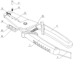
图1为本实用新型立体分解结构示意图;Fig. 1 is the three-dimensional exploded structure schematic diagram of the present utility model;
图2为本实用新型立体结构示意图;Fig. 2 is the three-dimensional structure schematic diagram of the present utility model;
图3为本实用新型主视结构示意图;Fig. 3 is the front view structure schematic diagram of the utility model;
图4为本实用新型的第一钳臂立体结构示意图;FIG. 4 is a schematic diagram of the three-dimensional structure of the first clamp arm of the present invention;
图5为本实用新型的第二钳臂立体结构示意图;FIG. 5 is a schematic three-dimensional structure diagram of the second clamp arm of the present invention;
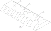
图6为本实用新型的剥线刀立体结构示意图。6 is a schematic diagram of the three-dimensional structure of the wire stripper of the present invention.
图中:1、第一钳臂;2、第一钳口;3、第一手柄;4、第一切断段;5、第一剥线段;6、第一拧紧段;7、第一剥线口;8、挂钩;9、第二钳臂;10、第二钳口;11、第二手柄;12、第二切断段;13、第二剥线段;14、第二拧紧段;15、安装槽;16、剥线刀;17、调整轴;18、第一弹簧;19、第二剥线口;20、定位柱;21、定位孔;22、连接槽;23、第二弹簧;24、防滑齿牙。In the figure: 1. The first clamp arm; 2. The first jaw; 3. The first handle; 4. The first cutting section; 5. The first stripping section; 6. The first tightening section; 7. The first stripping mouth; 8, hook; 9, second clamp arm; 10, second jaw; 11, second handle; 12, second cutting section; 13, second stripping section; 14, second tightening section; 15, installation Slot; 16, stripping knife; 17, adjusting shaft; 18, first spring; 19, second stripping port; 20, positioning post; 21, positioning hole; 22, connecting slot; 23, second spring; 24, Anti-slip teeth.
具体实施方式Detailed ways
为了便于理解本实用新型,下面将参照相关附图对本实用新型进行更全面的描述。In order to facilitate the understanding of the present utility model, the present utility model will be more fully described below with reference to the related drawings.
参照图1-图6,一种方便接线的电线剥线钳,包括第一钳臂1和第二钳臂9,第一钳臂1和第二钳臂9通过销轴相互铰接,第一钳臂1包括第一钳口2和第一手柄3,第二钳臂9包括第二钳口10和第二手柄11,第一手柄3和第二手柄11上均加工有防滑凸起,用于增大手与手柄之间的摩擦力,增强使用时握持的稳定性,在第一手柄3和第二手柄11之间安装有第二弹簧23,第二弹簧23一端顶紧在第一手柄3上,第二弹簧23另一端顶紧在第二手柄11上,通过弹簧的弹力,可使第一钳口2和第二钳口10处于张开状态,方便使用者使用,在第一手柄3的尾端安装有一个可转动的挂钩8,在第二手柄11的尾端加工有连接槽22,当不使用时,可通过转动挂钩8,使挂钩8的活动端卡装在连接槽22内,此时第一钳口2和第二钳口10处于闭合状态,方便放置和携带,可避免钳口对使用者造成伤害,提高收纳和携带的安全性,第一钳口2包括依次加工而成的第一切断段4、第一剥线段5和第一拧紧段6,第二钳口10包括依次加工而成的第二切断段12、第二剥线段13和第二拧紧段14,第二切断段12与第一切断段4相对应,用于电线的截断,第二拧紧段14与第一拧紧段6相对应,可用于剥线后进行接线螺栓的拧紧,无需使用额外的工具,在第一拧紧段6和第二拧紧段14的内侧均加工有防滑齿牙24,通过防滑齿牙24增大拧紧时的摩擦力,使得螺栓能够拧紧更加充分,第二剥线段13与第一剥线段5相对应,在第一剥线段5上加工有若干不同直径的第一剥线口7,可适应多规格电线的剥线要求,在第二剥线段13的底面加工有安装槽15,安装槽15内安装有快换剥线组件,快换剥线组件包括剥线刀16、调整轴17和第一弹簧18,剥线刀16安装在安装槽15内,剥线刀16的两侧加工有若干不同直径的第二剥线口19,第二剥线口19与第一剥线口7相匹配,可满足多规格电箱的剥线要求,调整轴17滑动穿透第二剥线段13与剥线刀16通过螺纹连接,第一弹簧18套装在调整轴17上,且位于第二剥线段13的上方,在剥线刀16的上表面加工有若干定位柱20,第二剥线段13上加工有与定位柱20相匹配的若干定位孔21,利用相互匹配的定位柱20和定位孔21对剥线刀16进行定位,提高剥线刀16的稳固,保证剥线的效率。1-6, a wire stripper for easy wiring includes a first clamp arm 1 and a second clamp arm 9. The first clamp arm 1 and the second clamp arm 9 are hinged to each other through a pin shaft. The first clamp arm The arm 1 includes a
使用时,将挂钩8的活动端从连接槽22中取出,在第二弹簧23的作用下,第一钳口2和第二钳口10张开,根据需要剥线的电线的规格,调整剥线刀16上相应规格的第二剥线口19,调整时,按压调整轴17,压缩第一弹簧18,调整轴17带动剥线刀16从安装槽15中脱出,转动调整轴17带动剥线刀16同步转动,将剥线刀16上所需的第二剥线口19所在的一侧转动至与第一剥线口7相对应的一侧,放松对调整轴17的压紧,调整轴17在第一弹簧18的作用下弹起,使剥线刀16重新安装回安装槽15内,定位柱20卡装入定位孔21内进行定位,将电线放入相对应的第一剥线口7和第二剥线口19内,通过收缩第一手柄3和第二手柄11,完成电线的剥线工作,将剥线完成的电线接入接线处,通过第一拧紧段6和第二拧紧段14将接线螺栓拧紧,并根据电线使用长度的需要,通过第一切断段4和第二切断段12将电线截断,同时完成剥线、断线和拧紧作业。When in use, the movable end of the
需要特别说明的是,在本实用新型的实施例中所述的第一弹簧18、第二弹簧23、销轴和接线螺栓均为现有技术应用。It should be noted that the
在本专利的描述中,需要理解的是,术语“上”、“下”、“内”、“外”、“中心”等指示的方位或位置关系为基于附图所示的方位或位置关系,仅是为了便于描述本专利和简化描述,而不是指示或暗示所指的装置或元件必须具有特定的方位、以特定的方位构造和操作,因此不能理解为对本专利的限制。In the description of this patent, it should be understood that the orientation or positional relationship indicated by the terms "upper", "lower", "inner", "outer", "center", etc. is based on the orientation or positional relationship shown in the accompanying drawings , is only for the convenience of describing the present patent and simplifying the description, rather than indicating or implying that the indicated device or element must have a specific orientation, be constructed and operated in a specific orientation, and therefore should not be construed as a limitation on this patent.
在本专利中,除非另有明确的规定和限定,术语“组合”、“设置”、“连接”、“固定”、“紧密”等术语应做广义理解,例如,可以是固定连接,也可以是可拆卸连接,或成一体;可以是机械连接,也可以是电连接;可以是直接相连,也可以通过中间媒介间接相连,可以是两个元件内部的连通或两个元件的相互作用关系,除非另有明确的限定,对于本领域的普通技术人员而言,可以根据具体情况理解上述术语在本专利中的具体含义。In this patent, unless otherwise expressly specified and limited, the terms "combination", "arrangement", "connection", "fixation", "closeness" and other terms should be understood in a broad sense, for example, it may be a fixed connection, or It is a detachable connection, or integrated; it can be a mechanical connection or an electrical connection; it can be directly connected or indirectly connected through an intermediate medium, it can be the internal connection of two elements or the interaction relationship between the two elements, Unless otherwise clearly defined, those of ordinary skill in the art can understand the specific meanings of the above terms in this patent according to specific situations.
以上所述,仅为本实用新型较佳的具体实施方式,但本实用新型的保护范围并不局限于此,任何熟悉本技术领域的技术人员在本实用新型揭露的技术范围内,根据本实用新型的技术方案及其实用新型构思加以等同替换或改变,都应涵盖在本实用新型的保护范围之内。The above description is only a preferred embodiment of the present invention, but the protection scope of the present invention is not limited to this. Equivalent replacement or modification of the new technical solution and its utility model concept shall be included within the protection scope of the present utility model.
此外,应当理解,虽然本说明书按照实施方式加以描述,但并非每个实施方式仅包含一个独立的技术方案,说明书的这种叙述方式仅仅是为清楚起见,本领域技术人员应当将说明书作为一个整体,各实施例中的技术方案也可以经适当组合,形成本领域技术人员可以理解的其他实施方式。In addition, it should be understood that although this specification is described in terms of embodiments, not each embodiment only includes an independent technical solution, and this description in the specification is only for the sake of clarity, and those skilled in the art should take the specification as a whole , the technical solutions in each embodiment can also be appropriately combined to form other implementations that can be understood by those skilled in the art.
Claims (7)
Priority Applications (1)
| Application Number | Priority Date | Filing Date | Title |
|---|---|---|---|
| CN202123265880.XU CN217010157U (en) | 2021-12-23 | 2021-12-23 | Wire stripping pliers convenient for wiring |
Applications Claiming Priority (1)
| Application Number | Priority Date | Filing Date | Title |
|---|---|---|---|
| CN202123265880.XU CN217010157U (en) | 2021-12-23 | 2021-12-23 | Wire stripping pliers convenient for wiring |
Publications (1)
| Publication Number | Publication Date |
|---|---|
| CN217010157U true CN217010157U (en) | 2022-07-19 |
Family
ID=82387346
Family Applications (1)
| Application Number | Title | Priority Date | Filing Date |
|---|---|---|---|
| CN202123265880.XU Active CN217010157U (en) | 2021-12-23 | 2021-12-23 | Wire stripping pliers convenient for wiring |
Country Status (1)
| Country | Link |
|---|---|
| CN (1) | CN217010157U (en) |
Cited By (1)
| Publication number | Priority date | Publication date | Assignee | Title |
|---|---|---|---|---|
| CN107673593A (en) * | 2017-10-10 | 2018-02-09 | 彩虹(合肥)光伏有限公司 | A kind of solar energy photovoltaic glass cuts the new clamp that machine changes break bar |
-
2021
- 2021-12-23 CN CN202123265880.XU patent/CN217010157U/en active Active
Cited By (2)
| Publication number | Priority date | Publication date | Assignee | Title |
|---|---|---|---|---|
| CN107673593A (en) * | 2017-10-10 | 2018-02-09 | 彩虹(合肥)光伏有限公司 | A kind of solar energy photovoltaic glass cuts the new clamp that machine changes break bar |
| CN107673593B (en) * | 2017-10-10 | 2023-08-22 | 彩虹(合肥)光伏有限公司 | Novel calliper of solar photovoltaic glass cutter change knife flywheel |
Similar Documents
| Publication | Publication Date | Title |
|---|---|---|
| CN218633074U (en) | A wire stripper capable of cutting cables | |
| CN208528879U (en) | Electric energy metering easy positioning lead sealing pliers | |
| CN211163583U (en) | Multifunctional tool pliers | |
| CN222749998U (en) | A diagonal pliers for electrical engineering | |
| CN206225909U (en) | Cable positions wire stripper | |
| CN212399285U (en) | Integrative pincers of trimming wire stripping | |
| CN202742392U (en) | Hand tool for stripping and cutting | |
| CN113681476A (en) | Multifunctional bolt clipper structure based on communication | |
| CN209389588U (en) | A kind of cable stripper | |
| CN205290720U (en) | Novel special vice is unsealed to multi -functional electric power | |
| CN207273153U (en) | A kind of nipper plier | |
| CN206825254U (en) | electrician combination tool | |
| CN211278274U (en) | Be used for high pressure to use power inspection multifunctional tool | |
| CN210379745U (en) | Cable stripping device | |
| CN210443942U (en) | A multifunctional wire stripper | |
| CN222127485U (en) | Multifunctional wire stripper with hooks | |
| CN204741157U (en) | Crimping pliers | |
| CN216851095U (en) | A new type of wire stripper | |
| CN2560135Y (en) | Multifunction cable cutter | |
| CN220575645U (en) | Wire stripper with side wire dividing and spanner functions | |
| CN207069459U (en) | Relay protection wireline operations instrument | |
| CN223246061U (en) | Wire pressing pliers convenient for wiring | |
| CN114678811B (en) | a wire stripper | |
| CN219321944U (en) | Multifunctional electrician pliers | |
| CN211992549U (en) | An easy-to-use insulating shearing pliers |
Legal Events
| Date | Code | Title | Description |
|---|---|---|---|
| GR01 | Patent grant | ||
| GR01 | Patent grant | ||
| TR01 | Transfer of patent right | ||
| TR01 | Transfer of patent right |
Effective date of registration: 20250904 Address after: 321300Zhejiang ProvinceJinhua CityYongkang CityZhiying TownZhiying Third VillageShangxitan Industrial BaseNo. 18-2 Patentee after: Jinhua Zesheng Technology Co.,Ltd. Country or region after: China Address before: 257000 No. 363, Beier Road, Dongying District, Dongying City, Shandong Province Patentee before: DONGYING JUNCHEN PETROLEUM EQUIPMENT Co.,Ltd. Country or region before: China |