CN217002003U - Valve timing adjusting device - Google Patents
Valve timing adjusting device Download PDFInfo
- Publication number
- CN217002003U CN217002003U CN201990001466.XU CN201990001466U CN217002003U CN 217002003 U CN217002003 U CN 217002003U CN 201990001466 U CN201990001466 U CN 201990001466U CN 217002003 U CN217002003 U CN 217002003U
- Authority
- CN
- China
- Prior art keywords
- hole
- cover
- housing
- bolt
- fastening member
- Prior art date
- Legal status (The legal status is an assumption and is not a legal conclusion. Google has not performed a legal analysis and makes no representation as to the accuracy of the status listed.)
- Active
Links
- 230000000149 penetrating effect Effects 0.000 claims abstract description 7
- 230000002093 peripheral effect Effects 0.000 claims description 15
- 238000004381 surface treatment Methods 0.000 description 6
- 239000000446 fuel Substances 0.000 description 3
- 230000037431 insertion Effects 0.000 description 3
- 238000003780 insertion Methods 0.000 description 3
- 230000000694 effects Effects 0.000 description 2
- 238000005452 bending Methods 0.000 description 1
- 238000010586 diagram Methods 0.000 description 1
- 230000035515 penetration Effects 0.000 description 1
- 238000005480 shot peening Methods 0.000 description 1
Images


Classifications
-
- F—MECHANICAL ENGINEERING; LIGHTING; HEATING; WEAPONS; BLASTING
- F01—MACHINES OR ENGINES IN GENERAL; ENGINE PLANTS IN GENERAL; STEAM ENGINES
- F01L—CYCLICALLY OPERATING VALVES FOR MACHINES OR ENGINES
- F01L1/00—Valve-gear or valve arrangements, e.g. lift-valve gear
- F01L1/34—Valve-gear or valve arrangements, e.g. lift-valve gear characterised by the provision of means for changing the timing of the valves without changing the duration of opening and without affecting the magnitude of the valve lift
- F01L1/344—Valve-gear or valve arrangements, e.g. lift-valve gear characterised by the provision of means for changing the timing of the valves without changing the duration of opening and without affecting the magnitude of the valve lift changing the angular relationship between crankshaft and camshaft, e.g. using helicoidal gear
- F01L1/3442—Valve-gear or valve arrangements, e.g. lift-valve gear characterised by the provision of means for changing the timing of the valves without changing the duration of opening and without affecting the magnitude of the valve lift changing the angular relationship between crankshaft and camshaft, e.g. using helicoidal gear using hydraulic chambers with variable volume to transmit the rotating force
- F01L2001/34423—Details relating to the hydraulic feeding circuit
-
- F—MECHANICAL ENGINEERING; LIGHTING; HEATING; WEAPONS; BLASTING
- F16—ENGINEERING ELEMENTS AND UNITS; GENERAL MEASURES FOR PRODUCING AND MAINTAINING EFFECTIVE FUNCTIONING OF MACHINES OR INSTALLATIONS; THERMAL INSULATION IN GENERAL
- F16B—DEVICES FOR FASTENING OR SECURING CONSTRUCTIONAL ELEMENTS OR MACHINE PARTS TOGETHER, e.g. NAILS, BOLTS, CIRCLIPS, CLAMPS, CLIPS OR WEDGES; JOINTS OR JOINTING
- F16B33/00—Features common to bolt and nut
- F16B33/002—Means for preventing rotation of screw-threaded elements
Landscapes
- Engineering & Computer Science (AREA)
- General Engineering & Computer Science (AREA)
- Mechanical Engineering (AREA)
- Valve Device For Special Equipments (AREA)
- Connection Of Plates (AREA)
Abstract
A valve timing adjustment device (1) comprising: a cylindrical housing (2), the housing (2) rotating in synchronization with a crankshaft; a rotor (3) which is housed in the housing (2) and which rotates in synchronization with the camshaft; a first cover (4), wherein the first cover (4) has a first through hole (4a) and seals one opening (2c) of the housing (2); a second cover (5), wherein the second cover (5) has a second through hole (5a) and seals the other opening (2d) of the housing (2); a first fastening member (6) that fixes the first cover (4) and the housing (2) in a state in which the first fastening member (6) penetrates the first through hole (4 a); and a second fastening member (7), wherein the second fastening member (7) fixes the second cover (5) and the housing (2) in a state of penetrating through the second through hole (5 a).
Description
Technical Field
The present invention relates to a valve timing adjustment apparatus.
Background
A variable valve timing adjustment device (hereinafter referred to as "VVT") is a device that adjusts the opening/closing timing of an intake valve or an exhaust valve of an engine of a vehicle, and includes: a cylindrical housing that rotates in synchronization with the crankshaft; a rotor rotating in synchronization with a camshaft; a cover that closes one opening of the case; and a plate that closes the other opening of the case. A conventional VVT has a cover and a plate fixed to a housing by bolts in a state where a rotor is housed in the housing (see, for example, patent document 1).
[ Prior art documents ]
[ patent document ]
[ patent document 1]
Japanese patent laid-open publication No. 2017-101608
SUMMERY OF THE UTILITY MODEL
Technical problem to be solved by the utility model
In the conventional VVT described in patent document 1, a bolt is inserted from the plate side into a through hole of the plate and a through hole of the housing, and is fastened to a female screw portion formed in the cover. In the above configuration, the female screw portion formed in the cap has a shape protruding to the opposite side of the case, and therefore, the thickness of the VVT is increased by the thickness of the female screw portion. On the other hand, in the case where the female screw portion has a shape protruding toward the case, the thickness of the VVT can be reduced because the female screw portion is housed in the case, but since the axial force generated when fastening the bolt acts on the cover from the female screw portion, the entire cover bends, a gap is generated between the cover and the case, and oil leakage through the gap occurs.
The present invention has been made to solve the above-described problems, and an object of the present invention is to avoid a fastening structure by a female screw portion having a shape protruding to the opposite side of the housing and to suppress oil leakage.
Technical scheme for solving technical problem
The valve timing adjusting apparatus of the present invention includes: a cylindrical housing that rotates in synchronization with the crankshaft; a rotor housed in the housing and rotating in synchronization with the camshaft; a first cover having a first through hole and closing one opening of the housing; a second cover having a second through hole and closing the other opening of the housing; a first fastening member that fixes the first cover and the housing in a state of penetrating the first through hole; and a second fastening member that fixes the second cover and the housing in a state of penetrating the second through hole.
Effect of utility model
According to the present invention, since the female screw portions having a shape protruding to the opposite side of the case are not provided in the first cover and the second cover, the VVT can be thinned. Further, since the axial force generated when fastening the bolt does not act on the first cover and the second cover from the internal thread portion, the first cover and the second cover are not easily deformed, and oil leakage can be suppressed.
Drawings
Fig. 1 shows a configuration example of the VVT of embodiment 1, in which fig. 1 (a) is a front view, fig. 1 (B) is a rear view, fig. 1 (C) is a cross-sectional view taken along line a-a, and fig. 1 (D) is an enlarged view of a fastening structure.
Fig. 2 shows an example of a conventional VVT, in which fig. 2 (a) is a front view, fig. 2 (B) is a cross-sectional view taken along line B-B, and fig. 2 (C) is an enlarged view of a fastening structure.
Fig. 3 shows another example of a conventional VVT, in which fig. 3 (a) is a front view, fig. 3 (B) is a cross-sectional view taken along line C-C, and fig. 3 (C) is an enlarged view of a fastening structure.
Fig. 4 shows a configuration example of the VVT of embodiment 2, in which fig. 4 (a) is a front view, fig. 4 (B) is a D-D sectional view, and fig. 4 (C) is an enlarged view of a fastening structure.
Fig. 5 is a front view showing a configuration example of the VVT of embodiment 3, in which a first rotation stopper is provided in a flange portion.
Fig. 6 is a front view showing another configuration example of the VVT according to embodiment 3, in which a second rotation stopper is provided in a cylindrical portion.
Fig. 7 is an external perspective view of a nut having a second rotation stopper provided on a cylindrical portion.
Fig. 8 is an enlarged view of a fastening structure in the VVT of embodiment 4.
Detailed Description
Hereinafter, embodiments for carrying out the present invention will be described in more detail with reference to the accompanying drawings.
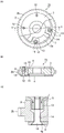
Fig. 1 is a diagram showing a configuration example of a VVT 1 according to embodiment 1, where fig. 1 (a) is a front view of the VVT 1, fig. 1 (B) is a rear view, fig. 1 (C) is a cross-sectional view taken along line a-a, and fig. 1 (D) is an enlarged view of a fastening structure. In fig. 1 (a), a part of the second cover 5 is omitted, and the internal structure of the housing 2 is exposed.
A plurality of hydraulic chambers 2a are formed inside the cylindrical housing 2. The plurality of hydraulic chambers 2a are partitioned into an advanced angle hydraulic chamber and a retarded angle hydraulic chamber by the rotor 3 housed in the housing 2, respectively. In a state where the rotor 3 is housed inside the casing 2, the first cover 4 is fixed to the casing 2 on the side of the first opening 2c, and the second cover 5 is fixed to the casing 2 on the side of the second opening 2 d. The first opening portion 2c and the second opening portion 2d of the housing 2 are closed, so that the hydraulic chamber 2a is sealed. A sprocket 2b is formed on the outer peripheral surface of the housing 2, and a timing belt, not shown, attached to the sprocket 2b transmits the driving force of the crankshaft of the engine to the housing 2, so that the housing 2 rotates in synchronization with the crankshaft. On the other hand, the rotor 3 is fixed to a camshaft, not shown, and rotates in synchronization with the camshaft. By changing the hydraulic pressure of the hydraulic chamber 2a, the rotational phase of the rotor 3 with respect to the housing 2 is changed.
As shown in fig. 1 (D), the case 2, the first cover 4, and the second cover 5 are integrated by bolts 6 and bolts 7. The bolt 6 is a "first fastening member", and the bolt 7 is a "second fastening member".
The first cover 4 has a first through hole 4a through which the bolt 6 passes. The housing 2 has a first screw hole 2e, which is provided at a position opposite to the first through hole 4a and to which the bolt 6 is fastened, 2 e. The bolt 6 passes through the first through hole 4a and is fastened to the first screw hole 2e of the housing 2. The first cover 4 and the housing 2 are fixed by fastening the bolt 6 to the first screw hole 2 e. In the fastened state of the bolt 6, the head of the bolt 6 is accommodated in the first through hole 4a, and therefore does not protrude outside the first cover 4.
The second cover 5 has a second through hole 5a through which the bolt 7 passes. The housing 2 has a second screw hole 2f, and the second screw hole 2f is provided at a position opposite to the second through hole 5a and is fastened by the bolt 7. The bolt 7 passes through the second through hole 5a and is fastened to the second screw hole 2f of the housing 2. The second cover 5 and the housing 2 are fixed by fastening the bolt 7 to the second screw hole 2 f. In the fastened state of the bolt 7, the head of the bolt 7 is accommodated in the second through hole 5a, and therefore does not protrude outside the second cover 5.
In the illustrated example, one end of one screw hole penetrating the housing 2 constitutes the first screw portion 2e, and the other end constitutes the second screw hole 2f, but the first screw hole 2e and the second screw hole 2f may be provided separately. The number of bolts 6 and 7 may be any number. In the illustrated example, the bolts 6 and 7 are countersunk screws, but the shapes of the bolts 6 and 7 may be arbitrary.
Next, effects obtained by the configuration of embodiment 1 will be described with reference to two conventional examples.
Fig. 2 shows an example of a conventional VVT 1a, in which fig. 2 (a) is a front view, fig. 2 (B) is a B-B sectional view, and fig. 2 (C) is an enlarged view of a fastening structure. In fig. 2, the same or corresponding portions as those in fig. 1 are denoted by the same reference numerals, and description thereof is omitted. In fig. 2 (a), a part of the second cover 5 is omitted, and the internal structure of the housing 2 is exposed.
In the conventional VVT 1a, the second cap 5 is provided with a female screw portion 10. The female screw portion 10 is formed to protrude toward the opposite side of the housing 2. The bolt 12 is inserted through the first through hole 4a provided in the first cover 4, and is inserted through the through hole 11 provided in the housing 2, and is fastened to the female screw portion 10. The first cover 4, the second cover 5, and the housing 2 are fixed by fastening the bolt 12 to the female screw portion 10. In the case of the above-described conventional example, since the female screw portion 10 has a shape facing the opposite side of the housing 2, the thickness of the VVT 1a is increased by the thickness of the female screw portion 10. The increase in thickness of the VVT 1a may hinder space saving of the engine.
However, in the case of the conventional example of fig. 2, the entire surface of the case 2 supports the case 2-side surface of the second cover 5, and therefore, even if an axial force generated when fastening the bolt 12 acts on the second cover 5, the second cover 5 is not easily bent. Therefore, a gap is less likely to be formed between the case 2 and the second cover 5, and leakage of oil from the hydraulic chamber 2a to the outside of the VVT 1a can be suppressed.
Fig. 3 shows another example of the existing VVT 1B, in which fig. 3 (a) is a front view, fig. 3 (B) is a cross-sectional view taken along line C-C, and fig. 3 (C) is an enlarged view of the fastening structure. In fig. 3, the same or corresponding portions as those in fig. 1 are denoted by the same reference numerals, and description thereof is omitted. In fig. 3 (a), a part of the second cover 5 is omitted, and the internal structure of the housing 2 is exposed.
In the conventional VVT 1b, the second cover 5 is provided with a female screw portion 13, similarly to the VVT 1 a. The female screw portion 13 is formed to protrude toward the case 2 side and is accommodated in the through hole 14 of the case 2. The bolt 12 is inserted through the first through hole 4a provided in the first cover 4 and the through hole 14 provided in the housing 2, and is fastened to the female screw portion 13. The first cover 4, the second cover 5, and the housing 2 are fixed by fastening the bolt 12 to the female screw portion 13. In the case of the above-described conventional example, since the fastening structure by the female screw portion 10 having a shape protruding to the opposite side of the housing 2 is avoided, the thickness of the VVT 1b can be reduced as compared with the VVT 1 a.
However, in the case of the conventional example shown in fig. 3, the axial force generated when the bolt 12 is tightened acts on the second cover 5 from the internal thread portion 13 to generate a rotational moment in the second cover 5, thereby bending the second cover 5 in the direction indicated by the arrow in fig. 3C. Therefore, a gap is generated between the housing 2 and the second cover 5, and oil leaks from the hydraulic chamber 2a to the outside of the VVT 1b through the gap. In order to drive the VVT 1b, the hydraulic pressure of the hydraulic chamber 2a that drops due to oil leakage needs to be increased, and as a result, the fuel efficiency of the engine is deteriorated.
In the VVT 1 of embodiment 1, the first screw holes 2e and the second screw holes 2f of the fastening bolts 6 and 7 are provided in the housing 2. That is, since the female screw portion 10 having a shape protruding to the opposite side of the case 2 is not provided in the first cover 4 and the second cover 5, the VVT 1 can be made thinner than the VVT 1 a. Therefore, space saving of the engine can be achieved. In addition, in the VVT 1 of embodiment 1, since the female screw portions 13 are not provided in the first cover 4 and the second cover 5, the axial force generated when fastening the bolts 6 and 7 does not act on the first cover 4 and the second cover 5 from the female screw portions 13. Therefore, the first cover 4 and the second cover 5 are less likely to be deformed, and oil leakage from the hydraulic chamber 2a to the outside of the VVT 1 can be suppressed. Thus, the fuel efficiency of the engine can be improved.
Fig. 4 shows a configuration example of the VVT 1 of embodiment 2, wherein fig. 4 (a) is a front view, fig. 4 (B) is a D-D sectional view, and fig. 4 (C) is an enlarged view of a fastening structure. In fig. 4, the same or corresponding portions as those in fig. 1 are denoted by the same reference numerals, and description thereof is omitted. In fig. 4 (a), a part of the second cover 5 is omitted, and the internal structure of the housing 2 is exposed.
In embodiment 1, the first fastening member and the second fastening member are bolts 6 and 7, but in embodiment 2, the first fastening member is a bolt 6 and the second fastening member is a nut 7 a. The nut 7a has a cylindrical portion 7b and a flange portion 7 d. The tube portion 7b has female threads 7c on the inner peripheral surface and penetrates through the second through hole 5a provided in the second cover 5. The flange portion 7d is provided on one end side of the tube portion 7b and is hooked on an edge portion of the second through hole 5 a.
The case 2 according to embodiment 2 has a third through hole 2g, and the third through hole 2g is provided at a position facing the first through hole 4a of the first cover 4 and the second through hole 5a of the second cover 5. The first cover 4 side of the third through hole 2g is a bolt insertion portion 2i through which the bolt 6 is inserted, and the second cover 5 side of the third through hole 2g is a cylindrical portion accommodating portion 2h which accommodates the cylindrical portion 7b of the nut 7 a. The bolt 6 is inserted through the first through hole 4a provided in the first cover 4, inserted through the bolt insertion hole 2i of the housing 2, and fastened to the female screw 7c of the cylindrical portion 7b accommodated in the cylindrical portion accommodating portion 2 h.
As described above, in embodiment 2, since the cylindrical portion 7b of the fastening bolt 6 is configured to be accommodated in the housing 2, the VVT 1 can be made thinner than the conventional VVT 1a shown in fig. 2. Further, since the axial force generated when the bolt 6 is tightened is vertically transmitted from the nut 7a to the second cover 5 as indicated by an arrow in fig. 4 (C), the rotational moment of the second cover 5 as in the conventional VVT 1b shown in fig. 3C does not occur. Therefore, the second cover 5 is not bent, and oil leakage from the hydraulic chamber 2a to the outside of the VVT 1 can be suppressed.
In the example of fig. 4, a recess 5b is provided in the second cover 5 at the edge of the second through hole 5a so that the flange 7d does not protrude outside the second cover 5. By housing the flange portion 7d in the recess portion 5b, the VVT 1 can be further thinned.
In the example of fig. 4, the cylindrical portion 7b of the nut 7a is housed in the case 2, but the cylindrical portion 7b may protrude to the opposite side of the case 2. In the case of the above configuration, since the second cover 5 is not bent by the axial force generated when the bolt 6 is fastened, oil leakage from the hydraulic chamber 2a to the outside of the VVT 1 can be suppressed.
In the example of fig. 4, the bolt 6 is provided on the first cover 4 side and the nut 7a is provided on the second cover 5 side, but the nut 7a may be provided on the first cover 4 side and the bolt 6 may be provided on the second cover 5 side.
In the VVT 1 of embodiment 2, since the cylindrical portion 7b of the nut 7a is housed in the case 2, it is difficult for the worker to stop the rotation of the nut 7a with a tool or the like when fastening the bolt 6 to the nut 7 a. In order to prevent the nut 7a from rotating when the bolt 6 is tightened, the frictional force between the flange portion 7d of the nut 7a and the recess portion 5b of the second cover 5 needs to be larger than the tightening torque of the bolt 6. For this reason, it is necessary to apply a surface treatment (e.g., shot peening) for increasing the friction coefficient to the flange portion 7d or the recess portion 5 b. The above surface treatment causes an increase in cost of the VVT 1. Therefore, in embodiment 3, a more inexpensive detent mechanism is added to the VVT 1 in place of the surface treatment.
Specifically, in embodiment 3, a rotation stopper having a shape that prevents rotation of the nut 7a when the bolt 6 is fastened to the nut 7a is provided on at least one of the flange portion 7d and the cylindrical portion 7b of the nut 7a shown in embodiment 2.
Fig. 5 is a front view showing a configuration example of the VVT 1 of embodiment 3, in which a first detent portion 7e is provided in a flange portion 7 d. In fig. 5, the same or corresponding portions as those in fig. 4 are denoted by the same reference numerals, and description thereof is omitted. In fig. 5, a part of the second cover 5 is omitted, and the internal structure of the housing 2 is exposed.
The flange portion 7d has a first rotation stopper 7e having a shape preventing rotation of the nut 7 a. In the example of fig. 5, the first rotation preventing portions 7e are two opposing flat surfaces provided on the outer peripheral portion of the flange portion 7 d. The shape of the first rotation stopper 7e is not limited to the shape shown in fig. 5, and may be one or more flat surfaces or a gear shape provided on the outer peripheral portion of the flange portion 7 d.
On the other hand, the second cover 5 has a first fitting portion 5e fitted to the first rotation stopper portion 7e of the flange portion 7 d. In the example of fig. 5, the first fitting portions 5e are two opposing flat surfaces provided on the inner peripheral portion of the recess portion 5 b. The shape of the first fitting portion 5e may be any shape that can fit into the first rotation stopper 7e and prevent rotation of the nut 7a, and may be adapted to the shape of the first rotation stopper 7 e.
As described above, in the example of fig. 5, the flange portion 7d has the first rotation stopper portion 7e having a shape preventing rotation of the nut 7 a. The second cover 5 has a first fitting portion 5e that fits with the first rotation stopper portion 7e of the flange portion 7 d. Since the first rotation stop portion 7e and the first fitting portion 5e can prevent the rotation of the nut 7a when the bolt 6 is fastened, the productivity of the VVT 1 is improved. Further, since the addition of the first rotation stopper 7e and the first fitting portion 5e is less expensive than the surface treatment, an increase in cost of the VVT 1 can be suppressed.
Fig. 6 is a front view showing another configuration example of the VVT 1 according to embodiment 3, in which a second rotation stopper 7j is provided in the cylindrical portion 7 b. Fig. 7 is an external perspective view of a nut 7a having a second rotation stopper 7j provided on a cylindrical portion 7 b. In fig. 6 and 7, the same or corresponding portions as those in fig. 4 are denoted by the same reference numerals, and the description thereof is omitted. In fig. 6, a part of the second cover 5 is omitted, and the internal structure of the housing 2 is exposed.
The cylinder portion 7b has a second rotation stopper 7j provided on the outer peripheral surface and shaped to prevent rotation of the nut 7 a. In the example of fig. 6 and 7, the second rotation stopper 7j is six flat surfaces provided on the outer peripheral surface of the cylindrical portion 7 b. The shape of the second rotation stopper 7j is not limited to the shape shown in fig. 6 and 7, and may be a flat surface or a gear shape provided on one or more flat surfaces on the outer peripheral portion of the cylindrical portion 7 b.
On the other hand, the housing 2 has a second fitting portion 2j provided on the inner peripheral surface of the third through hole 2g and fitted to the rotation stopper portion 7j of the tube portion 7 b. In the example of fig. 6, the second fitting portion 2j is six flat surfaces provided on the inner peripheral surface of the third through hole 2 g. The shape of the second fitting portion 2j may be any shape that can fit into the second rotation stopper 7j to prevent rotation of the nut 7a, and may be adapted to the shape of the second rotation stopper 7 j.
In the example of fig. 6 and 7, the cylindrical portion 7b has the second rotation stopper 7j provided on the outer peripheral surface and having a shape that prevents rotation of the nut 7 a. The housing 2 has a second fitting portion 2j provided on the inner peripheral surface of the third through hole 2g and fitted to the rotation stopper portion 7j of the tube portion 7 b. Since the second rotation stop portion 7j and the second fitting portion 2j can prevent the rotation of the nut 7a when the bolt 6 is fastened, the productivity of the VVT 1 is improved. Further, since the addition of the second rotation stopper 7j and the second fitting portion 2j is less expensive than the surface treatment, an increase in cost of the VVT 1 can be suppressed.
In addition, both the first rotation stopper 7e and the first fitting portion 5e, and the second rotation stopper 7j and the second fitting portion 2j may be added to the VVT 1.
In addition, when the cost increase of the VVT 1 is allowed, the surface treatment may be performed without adding the first rotation stopper 7e and the first fitting portion 5e, and the second rotation stopper 7j and the second fitting portion 2 j.
Fig. 8 is an enlarged view of the fastening structure of the VVT 1 of embodiment 4. In fig. 8, the same or corresponding portions as those in fig. 4 are denoted by the same reference numerals, and description thereof is omitted.
As shown in fig. 8, the cylindrical portion 7b of the nut 7a has a large inner diameter portion 7k through which the bolt 6 is inserted on the side opposite to the one end side where the flange portion 7d is provided. The inner diameter Φ 1 of the large inner diameter portion 7k is larger than the inner diameter Φ 2 of the bolt insertion portion 2i provided in the third through hole 2g of the case 2. Since Φ 1 > Φ 2, when the worker inserts the bolt 6 from the first through hole 4a of the first cover 4 and attaches it to the cylindrical portion 7b, the bolt 6 enters the large inner diameter portion 7k without riding on the edge portion of the cylindrical portion 7 b. This improves the assembling property of the bolt 6.
In addition, the fastening structure shown in fig. 8 may be added with the first rotation stopper 7e and the first fitting portion 5e, or the second rotation stopper 7j and the second fitting portion 2j, as shown in embodiment 3.
The present invention can freely combine the embodiments, change arbitrary components of the embodiments, or omit arbitrary components of the embodiments within a range where the present invention is novel in its practical use.
[ Industrial Applicability ]
The VVT of the present invention is reduced in thickness and suppressed in oil leakage, and therefore, is suitable for use in an engine requiring space saving and improved fuel efficiency.
(description of symbols)
1. 1a, 1b VVT; 2, a shell; 2a hydraulic chamber; 2b a sprocket; 2c a first opening; 2d a second opening; 2e a first threaded hole; 2f a second threaded hole; 2g of a third through hole; 2h cylinder part containing part; 2i bolt penetration part; 2j a second fitting portion; 3, a rotor; 4a first cover; 4a first via; 5a second cover; 5a second via; 5b a recess; 5e a first fitting part; 6 bolts (first fastening members); 7 bolts (second fastening members); 7a nuts (second fastening members); 7b a cylindrical part; 7c internal threads; 7d flange parts; 7e a first rotation stop portion; 7j a second rotation stop portion; a 7k large inner diameter part; 10. 13 an internal threaded portion; 11. 14 through holes; 12, bolts; phi 1 and phi 2.
Claims (6)
1. A valve timing adjustment apparatus, characterized by comprising:
a cylindrical housing that rotates in synchronization with the crankshaft;
a rotor housed in the housing and rotating in synchronization with a camshaft;
a first cover having a first through hole and closing one opening of the housing;
a second cover having a second through hole and closing the other opening of the housing;
a first fastening member that fixes the first cover and the housing in a state of penetrating the first through hole; and
a second fastening member that fixes the second cover and the housing in a state of penetrating the second through hole.
2. The valve timing adjusting apparatus according to claim 1,
the first fastening member and the second fastening member are bolts,
the housing has: a first screw hole provided at a position opposite to the first through hole and to which the first fastening member is fastened; and a second screw hole provided at a position opposite to the second through hole and for fastening the second fastening member.
3. The valve timing adjusting apparatus according to claim 1,
the second fastening member is a nut having a cylindrical portion provided with female threads on an inner peripheral surface thereof and penetrating the second through hole, and a flange portion provided on one end side of the cylindrical portion and hooked on an edge portion of the second through hole,
the first fastening member is a bolt fastened to the nut,
the housing has a third through hole provided at a position opposite to the first through hole and the second through hole, and the third through hole accommodates the cylindrical portion of the nut and allows the bolt to pass through.
4. The valve timing adjusting apparatus according to claim 3,
the flange portion has a first rotation stop portion having a shape preventing rotation of the nut,
the second cover has a first fitting portion that is fitted to the first rotation stop portion of the flange portion.
5. The valve timing adjusting apparatus according to claim 3,
the cylindrical portion has a second rotation stopper portion provided on an outer peripheral surface thereof and shaped to prevent rotation of the nut,
the housing has a second fitting portion that is provided on an inner peripheral surface of the third through hole and that is fitted to the second rotation stopper of the cylindrical portion.
6. The valve timing adjusting apparatus according to claim 3,
the cylindrical portion has a large inner diameter portion on a side opposite to the one end side where the flange portion is provided, and the large inner diameter portion has an inner diameter larger than an inner diameter of a portion of the third through hole through which the bolt is inserted, and through which the bolt is inserted.
Applications Claiming Priority (1)
| Application Number | Priority Date | Filing Date | Title |
|---|---|---|---|
| PCT/JP2019/041249 WO2021079396A1 (en) | 2019-10-21 | 2019-10-21 | Valve timing adjustment device |
Publications (1)
| Publication Number | Publication Date |
|---|---|
| CN217002003U true CN217002003U (en) | 2022-07-19 |
Family
ID=75620586
Family Applications (1)
| Application Number | Title | Priority Date | Filing Date |
|---|---|---|---|
| CN201990001466.XU Active CN217002003U (en) | 2019-10-21 | 2019-10-21 | Valve timing adjusting device |
Country Status (4)
| Country | Link |
|---|---|
| US (1) | US20220316366A1 (en) |
| JP (1) | JP7345558B2 (en) |
| CN (1) | CN217002003U (en) |
| WO (1) | WO2021079396A1 (en) |
Family Cites Families (15)
| Publication number | Priority date | Publication date | Assignee | Title |
|---|---|---|---|---|
| JPS6173911U (en) * | 1984-10-22 | 1986-05-19 | ||
| US4828441A (en) * | 1987-07-08 | 1989-05-09 | United Technologies Corporation | Locked threaded insert for high stress application |
| FR2690490A1 (en) * | 1992-04-27 | 1993-10-29 | Peugeot | Assembly of part against wall of hollow body - comprises first threaded part fixed on part to assembly, second complementary threaded part used as aligning socket, where second threaded part, aligning socket are single piece |
| JP3191846B2 (en) * | 1994-10-20 | 2001-07-23 | 株式会社デンソー | Valve timing adjustment device for internal combustion engine |
| DE19958541A1 (en) * | 1999-12-04 | 2001-06-07 | Schaeffler Waelzlager Ohg | Device for adjusting the angle of rotation of a camshaft |
| JP2002061609A (en) * | 2000-08-21 | 2002-02-28 | Ckd Corp | Connecting structure of cylinder and connecting method for cylinder |
| DE10054797A1 (en) * | 2000-11-04 | 2002-05-08 | Ina Schaeffler Kg | Procedure for rotational angle adjustment of camshaft relative to crankshaft utilizes planet gear which reacts to torque moments of crankshaft or camshaft with self-locking providing no rotational angle adjustment takes place |
| JP4386823B2 (en) * | 2004-11-11 | 2009-12-16 | 日鍛バルブ株式会社 | Phase variable device for automobile engine |
| JP4553795B2 (en) * | 2005-05-24 | 2010-09-29 | 日立オートモティブシステムズ株式会社 | Valve timing control device for internal combustion engine |
| DE102005041350A1 (en) * | 2005-08-31 | 2007-03-01 | Ejot Gmbh & Co. Kg | Female screw part for inserting into hole of plate, has flange of holt-melt adhesive, which is fused by rotational friction, where flange is provided at carrier surface of cone and carrier surface is turned toward plate |
| JP2009215881A (en) * | 2006-07-05 | 2009-09-24 | Mitsubishi Electric Corp | Valve timing adjustment device |
| DE102010009394A1 (en) * | 2010-02-26 | 2011-09-01 | Schaeffler Technologies Gmbh & Co. Kg | Device for variably setting the control times of gas exchange valves of an internal combustion engine |
| JP6329754B2 (en) * | 2013-11-22 | 2018-05-23 | 矢崎総業株式会社 | Parts with fastening members and their mounting methods |
| DE102014201608A1 (en) * | 2014-01-30 | 2015-07-30 | Schaeffler Technologies AG & Co. KG | Phaser |
| JP2016133163A (en) * | 2015-01-19 | 2016-07-25 | 三菱電機株式会社 | Fastening structure for fiber-reinforced plastic member and laser beam machine |
-
2019
- 2019-10-21 WO PCT/JP2019/041249 patent/WO2021079396A1/en active Application Filing
- 2019-10-21 US US17/634,171 patent/US20220316366A1/en not_active Abandoned
- 2019-10-21 CN CN201990001466.XU patent/CN217002003U/en active Active
- 2019-10-21 JP JP2021553175A patent/JP7345558B2/en active Active
Also Published As
| Publication number | Publication date |
|---|---|
| WO2021079396A1 (en) | 2021-04-29 |
| JPWO2021079396A1 (en) | 2021-04-29 |
| JP7345558B2 (en) | 2023-09-15 |
| US20220316366A1 (en) | 2022-10-06 |
Similar Documents
| Publication | Publication Date | Title |
|---|---|---|
| US7987829B2 (en) | Camshaft adjusting device | |
| US20120285407A1 (en) | Variable valve timing control apparatus of internal combustion engine | |
| WO2006095532A1 (en) | Valve opening/closing timing controller | |
| WO2011089809A1 (en) | Variable valve gear for internal combustion engine | |
| US20130269638A1 (en) | Valve timing control device | |
| US20120298058A1 (en) | System for attaching a camshaft phaser to a camshaft | |
| US7958857B2 (en) | Cam phaser helical bias spring having a square end for retention | |
| US9004028B2 (en) | Valve timing control apparatus | |
| US20100242881A1 (en) | Hydraulic camshaft adjuster having an axial screw plug | |
| KR20180100688A (en) | Valve timing adjustment device | |
| CN217002003U (en) | Valve timing adjusting device | |
| KR101502877B1 (en) | Valve opening-closing timing control device and method for attaching front member thereof | |
| JP5184403B2 (en) | Valve timing control device for internal combustion engine | |
| JP5179405B2 (en) | Valve timing control device for internal combustion engine | |
| EP2495406A1 (en) | Device for controlling timing of valve opening/closing | |
| US5645024A (en) | Camshaft end-play adjustment device | |
| US10968997B2 (en) | Anti-backlash structure for scissors gear | |
| JP5179406B2 (en) | Valve timing control device for internal combustion engine | |
| JP2009209719A (en) | Valve timing adjusting device | |
| JP2006299891A (en) | Driving force transmission device and valve timing adjusting device for internal combustion engine | |
| JP2007127057A (en) | Mounting structure for valve timing adjusting device | |
| JP7003024B2 (en) | Valve timing adjuster | |
| JP4294453B2 (en) | Internal combustion engine head cover | |
| JPH08312367A (en) | Crank sprocket for internal combustion engine | |
| JP5562104B2 (en) | Valve timing change device |
Legal Events
| Date | Code | Title | Description |
|---|---|---|---|
| GR01 | Patent grant | ||
| GR01 | Patent grant |