CN216997387U - Crane with movable balancing weight mechanism - Google Patents
Crane with movable balancing weight mechanism Download PDFInfo
- Publication number
- CN216997387U CN216997387U CN202123115557.4U CN202123115557U CN216997387U CN 216997387 U CN216997387 U CN 216997387U CN 202123115557 U CN202123115557 U CN 202123115557U CN 216997387 U CN216997387 U CN 216997387U
- Authority
- CN
- China
- Prior art keywords
- crane
- climbing tower
- fixedly connected
- balancing weight
- slip case
- Prior art date
- Legal status (The legal status is an assumption and is not a legal conclusion. Google has not performed a legal analysis and makes no representation as to the accuracy of the status listed.)
- Active
Links
Images


Abstract
The utility model belongs to the technical field of cranes, and particularly relates to a crane with a movable balancing weight mechanism, which comprises a climbing tower frame, a rotating device, a crane boom and a lifting hook, wherein the left side in the crane boom is provided with a balancing weight, the outer surface of the balancing weight is fixedly provided with a sliding box, the inner wall of the crane boom is fixedly provided with a sliding rail, the front side of the sliding box is fixedly connected with a sliding rod, one end of the sliding rod, which is far away from the sliding box, is fixedly connected with a limiting plate, and the right side of the sliding box is fixedly connected with a telescopic rod. This hoist with portable balancing weight mechanism, it is nearer apart from the driver's cabin at the davit of hoist, the driver drives the telescopic link pulling slip case through starting telescoping device in the driver's cabin, the slip case drives the slide bar and slides in the logical groove at the slide rail front and back to adjust the position of slip case and balancing weight, make the both sides weight of hoist keep roughly balanced, prevent that the jib loading boom atress of hoist is uneven, cause the hoist to have the possibility that takes place to turn on one's side.
Description
Technical Field
The utility model relates to the technical field of cranes, in particular to a crane with a movable balancing weight mechanism.
Background
The crane refers to a multi-action hoisting machine for vertically lifting and horizontally carrying heavy objects in a certain range. Also known as crown blocks, navigation cranes and cranes. The crane has the main characteristic that a driving cab and a hoisting control cab are combined into a whole, overcomes the defect that a track plate of a crawler crane (crawler crane) damages the road surface, and belongs to material handling machinery.
The afterbody of hoist generally disposes the balancing weight, and current hoist balancing weight generally is fixed, and when the davit of hoist was nearer apart from the driver's cabin, the balancing weight can cause the both sides unbalanced weight of hoist to lead to the jib loading boom atress of hoist uneven, make the hoist have the possibility of taking place to turn on one's side.
SUMMERY OF THE UTILITY MODEL
The present invention is directed to a crane with a movable counterweight mechanism to solve the problems set forth in the background art.
In order to achieve the purpose, the utility model provides the following technical scheme: the crane with the movable balancing weight mechanism comprises a climbing tower frame, a rotating device, a lifting arm and a lifting hook, wherein the rotating device is installed at the top of the climbing tower frame, the lifting arm is fixedly installed at the top of the rotating device, the lifting hook is connected to the right side of the bottom of the lifting arm, and a balancing weight is arranged on the left side of the inside of the lifting arm.
The outer fixed surface of balancing weight installs the slip case, the inner wall fixed mounting of jib loading boom has the slide rail, the positive fixedly connected with slide bar of slip case, the slide bar is kept away from the one end fixedly connected with limiting plate of slip case, the left side fixedly connected with spring shaft of slip case, the right side fixedly connected with telescopic link of slip case.
Preferably, logical groove has been seted up in the front of slide rail, the slide bar is connected with the inner wall sliding who leads to the groove, the spring shaft is kept away from the one end of slip case and the inner wall left side fixed connection of slide rail, the diameter of limiting plate is greater than the diameter that leads to the groove, the quantity of slide bar is two, two slide bar symmetric distribution is in the front and the back of slip case, and when the davit of hoist was nearer apart from the driver's cabin, the driver drove the telescopic link through starting the telescoping device and stretches out and draws back in the driver's cabin.
Preferably, the inside back fixed mounting of sliding box has bearing bar one, the surface middle part fixed mounting of bearing bar one has the adapter sleeve, the positive fixedly connected with tripod of adapter sleeve, the inside front fixed mounting of sliding box has bearing bar two.
Preferably, the sliding box is all run through to bearing bar one and bearing bar two, the quantity of tripod is two, two the tripod all with bearing bar two fixed connection, through be provided with bearing bar one and bearing bar two in the inside of sliding box, can play the supporting role to the balancing weight.
Preferably, a cross frame is fixedly mounted on the right side of the top of the crane boom, a lifting hook is slidably connected to the right side of the front of the crane boom, a tower cap is fixedly mounted at the center of the top of the crane boom, a tensioning device is fixedly mounted on the left side of the top of the crane boom, a cab is fixedly mounted on the right side of the bottom of the crane boom, a telescopic device is fixedly mounted on the left side of the bottom of the crane boom, and an output end of the telescopic device is fixedly connected with a telescopic rod.
Preferably, the slewing device comprises a slewing base, a motor, a slewing bearing, a rotating disc and a connecting shaft, wherein the slewing base is fixedly installed at the top of the climbing tower frame, the motor is fixedly installed at the center of the bottom of the slewing base, the slewing bearing is connected to the output end of the motor, the rotating disc is sleeved outside the slewing bearing, and the connecting shaft is fixedly connected to the top of the rotating disc.
Preferably, the motor is electrically connected with an external power supply, the top of the connecting shaft is fixedly connected with the crane boom, a driver pushes a rod in a cab to start the motor, an output shaft of the motor drives the slewing bearing to rotate, and the slewing bearing drives the rotating disc to rotate.
Compared with the prior art, the utility model has the beneficial effects that:
1. this hoist with portable balancing weight mechanism, at the davit of hoist near the driver's cabin, the driver drives the telescopic link through starting telescoping device and stretches out and draws back in the driver's cabin, the telescopic link pulling slip case, the slip case drives the slide bar and slides in the logical groove at the positive and back of slide rail, thereby adjust the position of slip case and balancing weight, make the both sides weight of hoist keep roughly balanced, prevent that the jib loading boom atress of hoist is uneven, cause the hoist to have the possibility that takes place to turn on one's side.
2. This hoist with portable balancing weight mechanism is provided with bearing bar one and bearing bar two through the inside at the sliding box, can start the supporting role to the balancing weight, and bearing bar one and bearing bar two all run through the balancing weight, can prevent that the balancing weight from dropping from the inside of sliding box, and the triangle-shaped bearing region that tripod and bearing bar formed has guaranteed the inside stability of sliding box.
Drawings
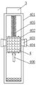
FIG. 1 is an elevational view of the overall construction of the present invention;
FIG. 2 is an enlarged schematic view of the point A in FIG. 1;
FIG. 3 is a schematic structural diagram of a rotating device according to the present invention;
FIG. 4 is a top view of the weight of the present invention;
fig. 5 is a top cross-sectional view of the slide box of the present invention.
In the figure: 1 climbing tower, 2 slewing gear, 201 slewing pedestal, 202 motor, 203 slewing bearing, 204 rotating disc, 205 connecting shaft, 3 lifting arms, 4 balancing weights, 401 sliding rails, 402 sliding box, 4021 bearing rod I, 4022 connecting sleeve, 4023 bearing rod II, 4024 tripod, 403 sliding rod, 404 limiting plate, 405 spring shaft, 406 telescopic rod, 407 telescopic device, 5 cross frame, 6 lifting hook, 7 tower cap, 8 tensioning device and 9 cab.
Detailed Description
The technical solutions in the embodiments of the present invention will be clearly and completely described below with reference to the drawings in the embodiments of the present invention, and it is obvious that the described embodiments are only a part of the embodiments of the present invention, and not all of the embodiments. All other embodiments, which can be derived by a person skilled in the art from the embodiments given herein without making any creative effort, shall fall within the protection scope of the present invention.
Referring to fig. 1-5, the present invention provides a technical solution: the crane with the movable balancing weight mechanism comprises a climbing tower 1 and a slewing gear 2, jib loading boom 3 and lifting hook 6, slewer 2 installs in the top of climbing pylon 1, jib loading boom 3 fixed mounting is in slewer's 2 top, lifting hook 6 is connected in jib loading boom 3's bottom right side, jib loading boom 3's inside left side is provided with balancing weight 4, jib loading boom 3's top right side fixed mounting has crossbearer 5, jib loading boom 3's front right side sliding connection has lifting hook 6, jib loading boom 3's top center fixed mounting has tower cap 7, jib loading boom 3's top left side fixed mounting has straining device 8, jib loading boom 3's bottom right side fixed mounting has driver's cabin 9, operating system in the driver's cabin 9 respectively with motor 202 and telescoping device 407 electric connection, lifting hook 6 lifts by crane to the heavy object, tower cap 7 and straining device 8 are taut jib loading boom 3 and crossbearer 5 through wire rope.
The slewing device 2 comprises a slewing pedestal 201, a motor 202, a slewing bearing 203, a rotating disc 204 and a connecting shaft 205, the slewing pedestal 201 is fixedly installed at the top of the climbing tower frame 1, the motor 202 is fixedly installed at the center of the bottom of the slewing pedestal 201, the slewing bearing 203 is connected to the output end of the motor 202, the rotating disc 204 is sleeved outside the slewing bearing 203, the connecting shaft 205 is fixedly connected to the top of the rotating disc 204, the motor 202 is electrically connected with an external power supply, the top of the connecting shaft 205 is fixedly connected with the crane boom 3, a driver starts the motor 202 in a cab 9, an output shaft of the motor 202 drives the slewing bearing 203 to rotate, the slewing bearing 203 drives the rotating disc 204 to rotate, so that the connecting shaft 205 drives the crane boom 3 to rotate, and the crane boom 3 is convenient to hoist heavy objects in different directions.
The outer surface of the balancing weight 4 is fixedly provided with a sliding box 402, the inner wall of the crane boom 3 is fixedly provided with a sliding rail 401, the front surface of the sliding box 402 is fixedly connected with a sliding rod 403, one end of the sliding rod 403 far away from the sliding box 402 is fixedly connected with a limiting plate 404, the left side of the sliding box 402 is fixedly connected with a spring shaft 405, the right side of the sliding box 402 is fixedly connected with a telescopic rod 406, the front surface and the back surface of the sliding rail 401 are both provided with through grooves, the sliding rod 403 is slidably connected with the inner wall of the through groove, one end of the spring shaft 405 far away from the sliding box 402 is fixedly connected with the left side of the inner wall of the sliding rail 401, the sliding box 402 can drive the spring shaft 405 to move when moving, the spring shaft 405 can play a role in buffering for the sliding box 402 when the sliding box 402 is reset, the diameter of the limiting plate 404 is larger than that of the through groove, the limiting plate 404 can prevent the sliding rod 403 from sliding out of the sliding rail 401, the number of the two sliding rods 403, the two sliding rods 403 are symmetrically distributed on the front surface and the back surface of the sliding box 402, the telescopic device 407 is fixedly mounted on the left side of the bottom of the crane boom 3, the output end of the telescopic device 407 is fixedly connected with the telescopic rod 406, when the crane boom is closer to the cab 9, a driver drives the telescopic rod 406 to stretch and retract by starting the telescopic device 407 in the cab 9, the telescopic rod 406 pulls the sliding box 402, the sliding box 402 drives the sliding rod 403 to slide in the through groove on the front side and the back side of the sliding rail 401, so that the positions of the sliding box 402 and the counterweight block 4 are adjusted, the weight of two sides of the crane is kept approximately balanced, the crane boom is prevented from being stressed unevenly, and the crane has the possibility of rollover.
The inside back fixed mounting of slide box 402 has first bearing bar 4021, the outer surface middle part fixed mounting of first bearing bar 4021 has adapter sleeve 4022, the front fixedly connected with tripod 4024 of adapter sleeve 4022, the inside front fixed mounting of slide box 402 has second bearing bar 4023, first bearing bar 4021 and second bearing bar 4023 all run through slide box 402, the quantity of tripod 4024 is two, two tripod 4024 all with second bearing bar 4023 fixed connection, through be provided with first bearing bar 4021 and second bearing bar 4023 in the inside of slide box 402, can play the supporting role to balancing weight 4, and first bearing bar 4021 and second bearing bar 4023 all run through balancing weight 4, can prevent that balancing weight 4 from dropping from the inside of slide box 402, the triangle-shaped bearing area that tripod 4024 and bearing bar formed, the inside stability of slide box 402 has been guaranteed.
When the crane is used, a driver drives the telescopic rod 406 to stretch and retract by starting the telescopic device 407 in the cab 9, the telescopic rod 406 pulls the sliding box 402, and the sliding box 402 drives the sliding rod 403 to slide in the through grooves in the front and the back of the sliding rail 401, so that the positions of the sliding box 402 and the counterweight 4 are adjusted, and the weights on two sides of the crane are kept approximately balanced.
Claims (7)
1. The crane with the movable balancing weight mechanism comprises a climbing tower (1), a rotating device (2), a crane arm (3) and a lifting hook (6), and is characterized in that: the lifting device comprises a slewing device (2), a lifting arm (3), a lifting hook (6), a balancing weight (4), a climbing tower (1), a climbing tower (2), a climbing tower (3), a climbing tower (2), a climbing tower (3), a climbing tower (4), a climbing tower (2), a climbing tower (3), a climbing tower (4), a climbing tower (3), a lifting hook (6), a climbing tower (3), a lifting tower (3), a climbing tower (4), a lifting tower (4) and a climbing tower (4);
the outer fixed surface of balancing weight (4) installs slip case (402), the inner wall fixed mounting of jib loading boom (3) has slide rail (401), the front fixedly connected with slide bar (403) of slip case (402), the one end fixedly connected with limiting plate (404) of slip case (402) are kept away from in slide bar (403), the left side fixedly connected with spring axle (405) of slip case (402), the right side fixedly connected with telescopic link (406) of slip case (402).
2. A crane having a movable counterweight mechanism as claimed in claim 1, wherein: lead to the groove has been seted up in the front of slide rail (401), slide bar (403) and the inner wall sliding connection who leads to the groove, the one end of slip case (402) and the inner wall left side fixed connection of slide rail (401) are kept away from in spring axle (405), the diameter of limiting plate (404) is greater than the diameter that leads to the groove, the quantity of slide bar (403) is two, two slide bar (403) symmetric distribution is in the front and the back of slip case (402).
3. A crane having a movable counterweight mechanism as claimed in claim 1, wherein: the inner back of the sliding box (402) is fixedly provided with a first bearing rod (4021), the middle of the outer surface of the first bearing rod (4021) is fixedly provided with a connecting sleeve (4022), the front of the connecting sleeve (4022) is fixedly connected with a tripod (4024), and the inner front of the sliding box (402) is fixedly provided with a second bearing rod (4023).
4. A crane having a movable counterweight mechanism as claimed in claim 3, wherein: the first bearing rod (4021) and the second bearing rod (4023) penetrate through the sliding box (402), the number of the triangular supports (4024) is two, and the two triangular supports (4024) are fixedly connected with the second bearing rod (4023).
5. A crane having a movable counterweight mechanism as claimed in claim 1, wherein: the top right side fixed mounting of jib loading boom (3) has crossbearer (5), the front right side sliding connection of jib loading boom (3) has lifting hook (6), the top center fixed mounting of jib loading boom (3) has tower cap (7), the top left side fixed mounting of jib loading boom (3) has straining device (8), the bottom right side fixed mounting of jib loading boom (3) has driver's cabin (9), the bottom left side fixed mounting of jib loading boom (3) has telescoping device (407), the output and telescopic link (406) fixed connection of telescoping device (407).
6. A crane having a movable counterweight mechanism as claimed in claim 1, wherein: the climbing tower is characterized in that the slewing device (2) comprises a slewing base (201), a motor (202), a slewing bearing (203), a rotating disc (204) and a connecting shaft (205), the slewing base (201) is fixedly mounted at the top of the climbing tower (1), the motor (202) is fixedly mounted at the center of the bottom of the slewing base (201), the slewing bearing (203) is connected to the output end of the motor (202), the rotating disc (204) is sleeved outside the slewing bearing (203), and the connecting shaft (205) is fixedly connected to the top of the rotating disc (204).
7. A crane having a movable counterweight mechanism as claimed in claim 6, wherein: the motor (202) is electrically connected with an external power supply, and the top of the connecting shaft (205) is fixedly connected with the crane arm (3).
Priority Applications (1)
| Application Number | Priority Date | Filing Date | Title |
|---|---|---|---|
| CN202123115557.4U CN216997387U (en) | 2021-12-13 | 2021-12-13 | Crane with movable balancing weight mechanism |
Applications Claiming Priority (1)
| Application Number | Priority Date | Filing Date | Title |
|---|---|---|---|
| CN202123115557.4U CN216997387U (en) | 2021-12-13 | 2021-12-13 | Crane with movable balancing weight mechanism |
Publications (1)
| Publication Number | Publication Date |
|---|---|
| CN216997387U true CN216997387U (en) | 2022-07-19 |
Family
ID=82383150
Family Applications (1)
| Application Number | Title | Priority Date | Filing Date |
|---|---|---|---|
| CN202123115557.4U Active CN216997387U (en) | 2021-12-13 | 2021-12-13 | Crane with movable balancing weight mechanism |
Country Status (1)
| Country | Link |
|---|---|
| CN (1) | CN216997387U (en) |
-
2021
- 2021-12-13 CN CN202123115557.4U patent/CN216997387U/en active Active
Similar Documents
| Publication | Publication Date | Title |
|---|---|---|
| CN201647849U (en) | Automatic balancing tower type crane | |
| CN209442536U (en) | A kind of crane of high stability | |
| CN106081904A (en) | Jib-type crane container spreader stabilizer | |
| CN115676644B (en) | Anti-swing outdoor portal crane | |
| CN215756065U (en) | Quick hoist device of construction is contained to prefabricated box of bridge | |
| CN214879790U (en) | Movable arm tower crane | |
| CN102303821B (en) | Luffing tower crane with balanced type suspension arm based on traction luffing of steel rope | |
| CN111217264A (en) | Crane with a movable crane | |
| CN202296907U (en) | Suspension arm balanced movable arm tower crane capable of luffing based on steel rope traction | |
| CN216997387U (en) | Crane with movable balancing weight mechanism | |
| CN108657968B (en) | Telescopic crane capable of preventing steel rope from falling off | |
| CN207209810U (en) | A kind of high raising Special Hoisting Equipment | |
| CN216737299U (en) | Bracket of tower crane | |
| CN117105114B (en) | Rocker arm and holding pole crawler type integrated equipment for electric power iron tower transportation and installation | |
| CN220056124U (en) | Rotary cantilever crane with stable structure | |
| CN2057658U (en) | Self-lifting type crane | |
| CN218619950U (en) | Electric hoist gantry crane hoisting device | |
| CN212559199U (en) | Hoisting mechanism with lever force increasing structure | |
| CN219950267U (en) | Electric single-beam crane with safety protection structure | |
| CN220245501U (en) | Arm head automatic leveling system | |
| CN215974668U (en) | Building construction material lifting device | |
| CN216549258U (en) | Safety production protection device for aviation crane | |
| CN220467380U (en) | Lifting device of gantry crane | |
| CN216945956U (en) | Tower crane with safety protection function | |
| CN117163848B (en) | Anti-backward tilting device of crane |
Legal Events
| Date | Code | Title | Description |
|---|---|---|---|
| GR01 | Patent grant | ||
| GR01 | Patent grant |