CN216966976U - Vertical numerical control rotary worktable for machining shell boring hole - Google Patents
Vertical numerical control rotary worktable for machining shell boring hole Download PDFInfo
- Publication number
- CN216966976U CN216966976U CN202220722700.1U CN202220722700U CN216966976U CN 216966976 U CN216966976 U CN 216966976U CN 202220722700 U CN202220722700 U CN 202220722700U CN 216966976 U CN216966976 U CN 216966976U
- Authority
- CN
- China
- Prior art keywords
- pressing plate
- pressing
- bolt
- numerical control
- processing
- Prior art date
- Legal status (The legal status is an assumption and is not a legal conclusion. Google has not performed a legal analysis and makes no representation as to the accuracy of the status listed.)
- Active
Links
Images



Landscapes
- Machine Tool Units (AREA)
Abstract
The utility model provides a vertical numerical control rotary worktable for processing shell boring holes, which comprises a servo motor and a main shaft disc controlled by the servo motor, wherein the main shaft disc is connected with a disc tailstock through a working turntable; the pressing mechanism consists of a limiting bolt, a mandrel and a pressing platform; the pressing platform is composed of a pressing plate and a pressing plate bolt, the pressing plate is inverted L-shaped, a groove is formed in the transverse end portion of the pressing plate, the head portion of the pressing plate bolt penetrates through the groove in the transverse end portion of the pressing plate, an adjusting nut is arranged at the head portion of the pressing plate bolt, and the adjusting nut is used for finely adjusting downward pressure of the pressing plate to fix an object. The utility model can realize the processing of two sides of the product through rotation, greatly improves the processing efficiency, reduces the clamping times and shortens the production time, and meanwhile, the pressing mechanism has simple structure and can complete the processing of the longitudinal holes on two sides of the shell by one-time clamping.
Description
Technical Field
The utility model relates to the technical field of tool machining, in particular to a high-precision rotary worktable of a three-axis numerical control machine tool.
Background
The machine tool main shaft for processing the machine tool of the three-axis numerical control machine tool, such as a typical numerical control gantry milling machine, a vertical processing center and the like, has the freedom of movement in three X/Y/Z directions, and can be used for processing various parts with complicated shapes, such as box parts, special-shaped parts and the like, including face milling processing, drilling processing, tapping processing and the like, through the programming of the numerical control system.
However, in the case (see fig. 6), in order to machine such a through hole, both ends of the through hole are required, and the part must be re-clamped a plurality of times and the surface must be clamped in a state perpendicular to the spindle of the machine tool. The processing method of repeated re-clamping needs a plurality of different clamping tools on one hand, so that the manufacturing cost is increased, on the other hand, a large amount of clamping time and adjusting time are consumed by repeated re-clamping, and the labor productivity is greatly reduced; one of the problems common to the prior art process equipment is: because the boring of the processed shell is limited by the structure and needs to be processed from two ends respectively, the original clamp and the addition component can not be matched with the precision of a three-axis numerical control machine tool, and the processing precision (coaxiality) of the three-axis numerical control machine tool is also influenced.
Disclosure of Invention
Aiming at the technical problem, the utility model provides a vertical numerical control workbench with rotatable through holes on two sides and firmly fixed shell.
The technical scheme of the utility model is as follows:
a vertical numerical control rotary worktable for processing shell boring holes comprises a servo motor and a main shaft disc controlled by the servo motor, wherein the main shaft disc is connected with a disc tailstock through a working rotary table, the working table seat is at least provided with a clamp base, and the clamp base is provided with a pressing mechanism; the pressing mechanism consists of a limiting bolt, a mandrel and a pressing platform; the pressing platform is composed of a pressing plate and a pressing plate bolt, the pressing plate is inverted L-shaped, a groove is formed in the transverse end portion of the pressing plate, the head portion of the pressing plate bolt penetrates through the groove in the transverse end portion of the pressing plate, an adjusting nut is arranged on the head portion of the pressing plate bolt, and the adjusting nut is used for finely adjusting downward pressure of the pressing plate to fix an object.
Furthermore, two clamp bases are arranged on the working table base.
The utility model has the beneficial effects that:
the pressing mechanism of the vertical numerical control rotary table is simple and practical, objects to be processed can be firmly fixed through three different points and surfaces, and moving is prevented, the technical scheme improves the production quantity and the production quality of enterprises, reduces the cost, improves the product precision, and improves the coaxial precision of the products from 0.30 to 0.01 and by more than 60%.
Drawings
FIG. 1 is a schematic structural diagram of a vertical numerically controlled rotary table for machining housing bores according to the present invention;
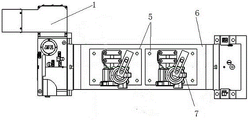
FIG. 2 is a top view of FIG. 1;
FIG. 3 is a front view of FIG. 1;
FIG. 4 is a left side view of FIG. 1;
FIG. 5 is a schematic view of a clamping arrangement of the clamp base of the present invention;
FIG. 6 is a cross-sectional view of the housing to be machined;
1-a servo motor; 2-a spindle disk; 3-a shell; 4-disc tailstock; 5-a clamp base; 6-working the rotary table; 7-a pressing mechanism; 71-a limit bolt; 72-a mandrel; 73-pressing the platform; 731-pressing plate; 732-platen bolts.
Detailed Description
The following description of the embodiments of the present invention will be made with reference to the accompanying drawings. The following examples are only for illustrating the technical solutions of the present invention more clearly, and the protection scope of the present invention is not limited thereby.
Fig. 1-4 show an embodiment of a vertical numerically controlled rotary table for machining housing bores according to the present invention, which includes a servo motor 1, a spindle disk 2, a disk tailstock 4, a fixture base 5, a working turntable 6 and a pressing mechanism 7, wherein the working turntable 6 for clamping the housing 3 is connected between the spindle disk 2 and the disk tailstock 4; the fixture base 5 is fixed on the working turntable 6.
The pressing mechanism 7 is fixed on the clamp base 5 and comprises a limiting bolt 71, a mandrel 72 and a pressing platform 73, the mandrel 72 can be sleeved in a longitudinal shaft hole b of the shell 3, the pressing platform 73 is used for fixing the shell 3 in a pressing mode from top to bottom, and the limiting bolt 71 can be adjusted by screws to be finely adjusted up and down to be used for further limiting the shell 3.
Referring to fig. 5, the pressing platform 73 is composed of a pressing plate 731 and a pressing plate bolt 732, the pressing plate 731 is in an inverted L shape, a slot is formed in a transverse end of the pressing plate 731, a head of the pressing plate bolt 732 penetrates through the slot in the transverse end of the pressing plate 731, and an adjusting nut is arranged on the head of the pressing plate bolt 732 and can finely adjust downward pressure on the pressing plate 731 to fix an object.
Referring to fig. 6, the longitudinal hole b of the housing 3 of the object to be processed is a hole to be processed, and the transverse hole a is a hole to be processed.
Specifically, firstly, the position of the shell 3 of the object to be processed on the clamp base 5 is adjusted, so that the longitudinal bore b is sleeved in the mandrel 72, and the hole to be processed on the shell 3 is aligned with the cutter on the three-axis numerical control machine tool; then, the pressing plate 731 is adjusted to press the object shell 3 to be processed, and the limit bolt 71 can be finely adjusted at the same time, so that the pressing mechanism can firmly clamp the object shell 3 to be processed; after the aperture of one surface of the object shell 3 to be machined is finished, the working turntable 6 rotates by 180 degrees, and the aperture of the other surface is machined.
The utility model can realize the processing of two sides of the product through rotation, greatly improves the processing efficiency, reduces the clamping times and shortens the production time, and simultaneously, the hold-down mechanism 7 has simple structure and can complete the processing of the longitudinal holes of two sides of the shell 3 through one-time clamping.
Claims (2)
1. A vertical numerical control rotary worktable for processing shell boring holes is characterized by comprising a servo motor and a main shaft disc controlled by the servo motor, wherein the main shaft disc is connected with a disc tailstock through a working turntable;
the pressing mechanism consists of a limiting bolt, a mandrel and a pressing platform;
the pressing table is composed of a pressing plate and a pressing plate bolt, the pressing plate is inverted L-shaped, a groove is formed in the transverse end portion of the pressing plate, the head portion of the pressing plate bolt penetrates through the groove in the transverse end portion of the pressing plate, an adjusting nut is arranged at the head portion of the pressing plate bolt, and the adjusting nut is used for finely adjusting downward pressure of the pressing plate and used for fixing an object.
2. The vertical numerically controlled rotary table of claim 1, wherein two fixture mounts are provided on the table base.
Applications Claiming Priority (2)
| Application Number | Priority Date | Filing Date | Title |
|---|---|---|---|
| CN2021221928557 | 2021-09-10 | ||
| CN202122192855 | 2021-09-10 |
Publications (1)
| Publication Number | Publication Date |
|---|---|
| CN216966976U true CN216966976U (en) | 2022-07-15 |
Family
ID=82341071
Family Applications (1)
| Application Number | Title | Priority Date | Filing Date |
|---|---|---|---|
| CN202220722700.1U Active CN216966976U (en) | 2021-09-10 | 2022-03-31 | Vertical numerical control rotary worktable for machining shell boring hole |
Country Status (1)
| Country | Link |
|---|---|
| CN (1) | CN216966976U (en) |
-
2022
- 2022-03-31 CN CN202220722700.1U patent/CN216966976U/en active Active
Similar Documents
| Publication | Publication Date | Title |
|---|---|---|
| CN103231247B (en) | A kind of turntable type multi-head numerical control drilling and tapping machine tool | |
| TW201538266A (en) | Turning, milling and drilling comprehensive numerical control equipment | |
| US4697318A (en) | Adaptable machining system | |
| CN109277829A (en) | A kind of efficient numerically controlled longitudinal sectional turning-milling complex processing lathe | |
| CN107350748A (en) | A kind of V-type machine body inclined-plane and the processing method of beveled aperture system | |
| CN2825173Y (en) | Digital control horizontal boring milling machine | |
| CN210255284U (en) | Four-axis rotating tool clamp | |
| CN216966976U (en) | Vertical numerical control rotary worktable for machining shell boring hole | |
| CN209793118U (en) | High-rigidity core-walking type numerical control lathe | |
| CN210789393U (en) | Miniature five-axis numerical control milling machine with harmonic reducer and indexing turntable type structure | |
| CN217096749U (en) | Double-spindle numerical control lathe capable of realizing multi-process machining | |
| CN106271679A (en) | A kind of pentahedron composite processing machine tool | |
| CN213351604U (en) | Bottle blowing mold processing clamp | |
| CN108856784A (en) | Floor-type vertical-horizontal combined boring-milling numerical control machine tool | |
| CN211162856U (en) | Double-spindle gantry frame type machine tool | |
| CN114083298A (en) | Five-surface composite movable beam W-axis flexible manufacturing equipment | |
| CN210255398U (en) | Clamp for milling radial groove of part | |
| CN112872830A (en) | Intelligent elevator moving and static plate machining production line | |
| CN113732757A (en) | Clamp for processing machine tool cushion block and processing method thereof | |
| CN208729157U (en) | A kind of process equipment about crankshaft | |
| CN112317771A (en) | Double-saddle numerical control lathe and manufacturing method | |
| CN113941726A (en) | Double-movable-column double-spindle vertical machining center for rear axle housing sheet | |
| CN219211699U (en) | Novel through hole and terminal surface processing device | |
| CN214212224U (en) | Special machine for machining motor shell of double-saddle numerical control lathe | |
| CN216029364U (en) | Processing clamping tool |
Legal Events
| Date | Code | Title | Description |
|---|---|---|---|
| GR01 | Patent grant | ||
| GR01 | Patent grant |