CN216870635U - High-voltage test cable fixing device - Google Patents
High-voltage test cable fixing device Download PDFInfo
- Publication number
- CN216870635U CN216870635U CN202220312535.2U CN202220312535U CN216870635U CN 216870635 U CN216870635 U CN 216870635U CN 202220312535 U CN202220312535 U CN 202220312535U CN 216870635 U CN216870635 U CN 216870635U
- Authority
- CN
- China
- Prior art keywords
- clamping plate
- screw rod
- fixing device
- splint
- ceramic
- Prior art date
- Legal status (The legal status is an assumption and is not a legal conclusion. Google has not performed a legal analysis and makes no representation as to the accuracy of the status listed.)
- Expired - Fee Related
Links
- 238000012360 testing method Methods 0.000 title claims abstract description 28
- 239000000919 ceramic Substances 0.000 claims abstract description 20
- 238000003466 welding Methods 0.000 claims description 2
- 238000001816 cooling Methods 0.000 abstract description 3
- 238000001514 detection method Methods 0.000 description 2
- 230000000694 effects Effects 0.000 description 2
- 238000002474 experimental method Methods 0.000 description 2
- 230000000149 penetrating effect Effects 0.000 description 2
- 206010010904 Convulsion Diseases 0.000 description 1
- 230000009286 beneficial effect Effects 0.000 description 1
- 230000036461 convulsion Effects 0.000 description 1
- 238000010586 diagram Methods 0.000 description 1
- 238000006073 displacement reaction Methods 0.000 description 1
- 238000009434 installation Methods 0.000 description 1
- 238000012986 modification Methods 0.000 description 1
- 230000004048 modification Effects 0.000 description 1
Images


Abstract
The utility model discloses a high-voltage test cable fixing device which comprises an L-shaped clamping plate, a ceramic clamping block, a first screw rod and a second screw rod, wherein the clamping plate is arranged on one side of the bottom of the L-shaped clamping plate, the clamping plate is arranged on the top of the L-shaped clamping plate, the ceramic clamping block is arranged on one side of the bottom of the L-shaped clamping plate and on one side of the clamping plate through bolts, a wire clamping groove is formed in one side of the ceramic clamping block, an air guide groove is formed in the other side of the ceramic clamping block, and a draught fan penetrates through the other side of the bottom of the L-shaped clamping plate and the other side of the clamping plate through bolts. Whole high-voltage testing cable fixing device is stable in use safely, can help personnel to fix the cable of multiple specification to supply that personnel are better to carry out high-voltage testing to the cable, and possess good cooling part, in order to avoid the inside temperature of fixed part to save too high, the experimental stability of greatly increased has higher practicality.
Description
Technical Field
The utility model relates to the technical field of cables, in particular to a high-voltage test cable fixing device.
Background
When the cable is used, a person is required to carry out a high-voltage test on the cable in a spot check mode, and during the test, the end portion of the cable needs to be connected with the detection equipment, the height of the detection equipment cannot be parallel to the cable, the cable is connected with the equipment and then appears in a falling state, and the connection stability of the cable and the equipment is poor.
At present, a part which can help personnel to fix a cable to be subjected to a high-voltage test is lacked, so that the connection stability between the cable and test equipment is poor. Therefore, a high-voltage test cable fixing device is provided.
SUMMERY OF THE UTILITY MODEL
The utility model mainly aims to provide a high-voltage test cable fixing device which can effectively solve the problems in the background technology.
In order to achieve the purpose, the utility model adopts the technical scheme that:
the utility model provides a high-tension test cable fixing device, includes L type splint, clamp and splint, still includes ceramic clamp splice, first screw rod and second screw rod, L type splint bottom one side is equipped with the clamp, L type splint top is equipped with splint, ceramic clamp splice is all installed through the bolt to L type splint bottom one side and clamp one side, the card wire casing has been seted up to ceramic clamp splice one side, the induced air groove has been seted up to ceramic clamp splice opposite side, L type splint bottom opposite side and clamp opposite side all run through the bolt and install the suction fan.
Further, first screw rod is worn to be equipped with through the screw thread at the splint top, first screw rod one end is passed through the bearing and is connected with L type splint rotation, first guide bar is worn to be equipped with in splint top both sides, first guide bar one end and L type splint bolt erection joint.
Furthermore, a second screw rod is inserted into one end of the clamping plate through threads, the bottom of the second screw rod is rotatably connected with the L-shaped clamping plate through a bearing, second guide rods are respectively inserted into two sides of one end of the clamping plate, and the bottom of each second guide rod is connected with the L-shaped clamping plate through a bolt in an installing mode.
Further, the first screw rod and the second screw rod are all welded with a hand wheel, and a storage battery is installed on one side of the clamping plate through a bolt.
Compared with the prior art, the utility model has the following beneficial effects:
1. the subassembly that personnel passed through L type splint, clamp plate, splint, pottery clamp splice, first screw rod and second screw rod and constitute realizes providing high-voltage test's mounting fixture for the cable to make on required experimental cable can press from both sides the experimental support body or the panel of establishing and being fixed in the required use of personnel, and possess good insulating part, possess good radiating component, radiating effect during the greatly increased cable is experimental increases experimental stability.
2. Whole high-voltage testing cable fixing device is safe in utilization, can help personnel to fix the cable of multiple specification to supply that personnel are better to carry out high-voltage testing to the cable, and possess good cooling part, collect together too high with the inside temperature of avoiding fixed part, greatly increased test's stability has higher practicality.
Drawings
Fig. 1 is a schematic overall structure diagram of a high-voltage test cable fixing device according to the present invention.
Fig. 2 is a schematic structural view of an L-shaped clamp plate of the high-voltage test cable fixing device of the utility model.
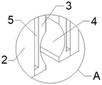
Fig. 3 is an enlarged schematic view of a part a in fig. 1 of a high-voltage test cable fixing device according to the utility model.
In the figure: 1. an L-shaped splint; 2. a wire clamping plate; 3. a ceramic clamping block; 4. a wire clamping groove; 5. a wind guide groove; 6. an exhaust fan; 7. a first screw; 8. a first guide bar; 9. a storage battery; 10. a splint; 11. a second guide bar; 12. a second screw; 13. a handwheel.
Detailed Description
In order to make the technical means, the creation characteristics, the achievement purposes and the effects of the utility model easy to understand, the utility model is further described with the specific embodiments.
As shown in fig. 1-3, a high-voltage testing cable fixing device, including L type splint 1, splint 2 and splint 10, still include ceramic clamp splice 3, first screw rod 7 and second screw rod 12, 1 bottom one side of L type splint is equipped with splint 2, 1 top of L type splint is equipped with splint 10, 1 bottom one side of L type splint and 2 one side of splint all install ceramic clamp splice 3 through the bolt, card wire casing 4 has been seted up to 3 one side of ceramic clamp splice, induced air groove 5 has been seted up to 3 opposite sides of ceramic clamp splice, 1 bottom opposite side of L type splint and 2 opposite sides of splint all run through the bolt and install suction fan 6.
The top of the clamping plate 2 is provided with a first screw rod 7 in a penetrating mode through threads, one end of the first screw rod 7 is rotatably connected with the L-shaped clamping plate 1 through a bearing, first guide rods 8 are arranged on two sides of the top of the clamping plate 2 in a penetrating mode, and one end of each first guide rod 8 is in bolt installation connection with the L-shaped clamping plate 1; the first guide bar 8 is used for guiding the direction in which the wire clamping plate 2 moves.
A second screw 12 is inserted into one end of the clamping plate 10 through threads, the bottom of the second screw 12 is rotatably connected with the L-shaped clamping plate 1 through a bearing, second guide rods 11 are respectively inserted into two sides of one end of the clamping plate 10, and the bottom of each second guide rod 11 is connected with the L-shaped clamping plate 1 through a bolt; the second guide bar 11 is used to guide the direction in which the chucking plate 10 moves.
The other ends of the first screw 7 and the second screw 12 are connected with hand wheels 13 in a welding mode, a storage battery 9 is mounted on one side of the clamping plate 2 through bolts, and the output end of the storage battery 9 is electrically connected with the input end of the exhaust fan 6 through a lead; the power supply for the suction fan 6 is realized by a storage battery 9, and the hand wheel 13 can help a person to rotate the corresponding first screw 7 and the second screw 12.
It should be noted that, the utility model is a high-voltage test cable fixing device, when working, a person uses the top of an L-shaped clamping plate 1 and a clamping plate 10 to lower the whole fixing device to be clamped on a panel such as a frame body or a table board to be used in a test, then rotates a second screw 12 to enable the clamping plate 10 to be connected with the second screw 12 through threads, so as to realize displacement of the end of the L-shaped clamping plate 1, enable the L-shaped clamping plate 1 and the clamping plate 10 to be fastened and fixed with foreign objects, then place a cable to be fixed in the test between the L-shaped clamping plate 1 and a ceramic clamping block 3 of a clamping plate 2, and use a wire clamping groove 4 on the ceramic clamping block 3 to realize clamping and fixing of the cable, when clamping, the person rotates a first screw 7 to enable the clamping plate 2 to be displaced, so that the ceramic clamping block 3 between the clamping plate 2 and the L-shaped clamping plate 1 can clamp the cable, thereby fixing the cable on equipment or a table board to be tested, in order to help the experiment more stable, during the experiment, personnel's accessible suction fan 6 carries out convulsions to 3 regions of pottery clamp splice for outside air gets into 3 backs of pottery clamp splice through induced air groove 5, is discharged outward by suction fan 6 again, makes the heat on the air can take away 3 surfaces of pottery clamp splice fast, realizes the cooling and handles, uses more stably with pottery clamp splice 3.
The foregoing shows and describes the general principles and features of the present invention, together with the advantages thereof. It will be understood by those skilled in the art that the present invention is not limited to the embodiments described above, which are described in the specification and illustrated only to illustrate the principle of the present invention, but that various changes and modifications may be made therein without departing from the spirit and scope of the present invention, which fall within the scope of the utility model as claimed. The scope of the utility model is defined by the appended claims and equivalents thereof.
Claims (4)
1. The utility model provides a high-voltage testing cable fixing device, includes L type splint (1), clamp (2) and splint (10), its characterized in that still includes ceramic clamp splice (3), first screw rod (7) and second screw rod (12), L type splint (1) bottom one side is equipped with clamp (2), L type splint (1) top is equipped with splint (10), ceramic clamp splice (3) are all installed through the bolt to L type splint (1) bottom one side and clamp (2) one side, card wire casing (4) have been seted up to ceramic clamp splice (3) one side, induced air groove (5) have been seted up to ceramic clamp splice (3) opposite side, L type splint (1) bottom opposite side and clamp (2) opposite side all run through the bolt and install suction fan (6).
2. The high-voltage test cable fixing device according to claim 1, wherein: first screw rod (7) are worn to be equipped with through the screw thread at double-layered line board (2) top, first screw rod (7) one end is passed through the bearing and is rotated with L type splint (1) and be connected, first guide bar (8) are worn to be equipped with in double-layered line board (2) top both sides, first guide bar (8) one end and L type splint (1) bolt erection joint.
3. The high-voltage test cable fixing device according to claim 1, wherein: the clamping device is characterized in that a second screw rod (12) is inserted into one end of the clamping plate (10) in a threaded manner, the bottom of the second screw rod (12) is rotatably connected with the L-shaped clamping plate (1) through a bearing, second guide rods (11) are respectively inserted into two sides of one end of the clamping plate (10), and the bottom of each second guide rod (11) is connected with the L-shaped clamping plate (1) through bolts in an installing manner.
4. The high-voltage test cable fixing device according to claim 1, wherein: the other ends of the first screw rod (7) and the second screw rod (12) are respectively connected with a hand wheel (13) in a welding mode, and the storage battery (9) is installed on one side of the clamp plate (2) through bolts.
Priority Applications (1)
| Application Number | Priority Date | Filing Date | Title |
|---|---|---|---|
| CN202220312535.2U CN216870635U (en) | 2022-02-16 | 2022-02-16 | High-voltage test cable fixing device |
Applications Claiming Priority (1)
| Application Number | Priority Date | Filing Date | Title |
|---|---|---|---|
| CN202220312535.2U CN216870635U (en) | 2022-02-16 | 2022-02-16 | High-voltage test cable fixing device |
Publications (1)
| Publication Number | Publication Date |
|---|---|
| CN216870635U true CN216870635U (en) | 2022-07-01 |
Family
ID=82155637
Family Applications (1)
| Application Number | Title | Priority Date | Filing Date |
|---|---|---|---|
| CN202220312535.2U Expired - Fee Related CN216870635U (en) | 2022-02-16 | 2022-02-16 | High-voltage test cable fixing device |
Country Status (1)
| Country | Link |
|---|---|
| CN (1) | CN216870635U (en) |
Cited By (1)
| Publication number | Priority date | Publication date | Assignee | Title |
|---|---|---|---|---|
| CN116930557A (en) * | 2023-05-15 | 2023-10-24 | 扬州京柏自动化科技有限公司 | Conduction test fixture |
-
2022
- 2022-02-16 CN CN202220312535.2U patent/CN216870635U/en not_active Expired - Fee Related
Cited By (1)
| Publication number | Priority date | Publication date | Assignee | Title |
|---|---|---|---|---|
| CN116930557A (en) * | 2023-05-15 | 2023-10-24 | 扬州京柏自动化科技有限公司 | Conduction test fixture |
Similar Documents
| Publication | Publication Date | Title |
|---|---|---|
| CN216870635U (en) | High-voltage test cable fixing device | |
| CN108809238A (en) | A kind of new-energy automobile photovoltaic power generation apparatus | |
| CN213184641U (en) | Wiring device for electric power engineering | |
| CN213122216U (en) | Positioning assembly for testing single battery cell | |
| CN215256613U (en) | Assembled cabin cover | |
| CN212587290U (en) | Anti-electricity-theft combined mutual inductor | |
| CN210608134U (en) | Box transformer substation measurement and control device supporting direct acquisition of 800V voltage | |
| CN215493813U (en) | Have wireless communication power analysis appearance convenient to installation | |
| CN217956990U (en) | Wind-resistant solar photovoltaic power generation equipment | |
| CN213088160U (en) | Wind power new energy power generation device | |
| CN220307152U (en) | Photovoltaic board mounting bracket with adjust structure | |
| CN219960521U (en) | Solar power generation photovoltaic inverter | |
| CN210722663U (en) | Insulating dry-type transformer | |
| CN213814408U (en) | Testing device for wind-solar hybrid street lamp controller | |
| CN110600642A (en) | Lithium battery cell structure | |
| CN218513938U (en) | High-efficient radiating block terminal carries out based on solar energy | |
| CN214746585U (en) | Roof type air source heat pump | |
| CN219204339U (en) | Frequency converter grounding wire connection structure | |
| CN212367819U (en) | Regulator cubicle terminal fixing device | |
| CN217690874U (en) | Moving contact dismounting fixture of high-voltage isolating switch | |
| CN211926457U (en) | A anchor clamps for lithium cell drying cabinet | |
| CN216079183U (en) | Test device for photovoltaic power generation capacity measurement and calculation | |
| CN216670173U (en) | Insulation fault detection device for automobile | |
| CN214703543U (en) | Monitoring device for pollutants in air environment | |
| CN214492568U (en) | Portable high-efficiency electrician patch |
Legal Events
| Date | Code | Title | Description |
|---|---|---|---|
| GR01 | Patent grant | ||
| GR01 | Patent grant | ||
| CF01 | Termination of patent right due to non-payment of annual fee |
Granted publication date: 20220701 |
|
| CF01 | Termination of patent right due to non-payment of annual fee |