CN216838978U - Bridge overhauls device - Google Patents
Bridge overhauls device Download PDFInfo
- Publication number
- CN216838978U CN216838978U CN202220428257.7U CN202220428257U CN216838978U CN 216838978 U CN216838978 U CN 216838978U CN 202220428257 U CN202220428257 U CN 202220428257U CN 216838978 U CN216838978 U CN 216838978U
- Authority
- CN
- China
- Prior art keywords
- bridge
- operation platform
- supporting plate
- fixedly connected
- connecting plate
- Prior art date
- Legal status (The legal status is an assumption and is not a legal conclusion. Google has not performed a legal analysis and makes no representation as to the accuracy of the status listed.)
- Active
Links
Images

Abstract
The application relates to the field of bridge detection technology, and discloses a bridge overhauls device, and it is including removing automobile body, elevating system and work platform, elevating system connects remove on the automobile body, work platform with elevating system connects, the elevating system drive work platform removes along the direction that is close to or keeps away from ground. This application has the height that can work platform and adjusts, makes the constructor on the work platform can overhaul the bridge at suitable height, improves the effect of overhauing the suitability of device.
Description
Technical Field
The application relates to the field of bridge detection technology, in particular to a bridge overhauling device.
Background
Along with the high-speed development of economic level and traffic technology, various bridges appear in China, after the bridges are used for a period of time, the bridges need to be overhauled regularly due to safety considerations, and the bridge is overhauled by generally placing an overhauling workbench on the outer side of the bridge through specific equipment and enabling an overhauling worker to overhaul the bridges on the workbench.
At present, a Chinese utility model patent with publication number CN215629366U discloses a bridge coating maintenance device, which comprises a travelling mechanism, wherein the travelling mechanism comprises a travelling frame and travelling wheels, the travelling frame is arranged on a bridge floor, and the travelling wheels are connected with the travelling frame and used for driving the travelling frame to move along the length direction of a bridge; the hanging rack is connected with the walking frame and hung outside the width direction of the bridge; the operation platform is connected with the hanging rack and is positioned below the bridge or outside the width direction of the bridge; and the balancing weight is arranged on the walking frame.
To the correlation technique among the above-mentioned, the inventor thinks that when running into the operation platform height inadequately, constructor need improve the operation height through the mode of trampling the rail horizontal pole on the operation platform in overhauing the bridge in-process, and the security is relatively poor, has the defect that overhauls the device suitability and is lower.
SUMMERY OF THE UTILITY MODEL
In order to alleviate the lower problem of overhauing device suitability, this application provides a bridge overhauls device.
The application provides a bridge overhauls device adopts following technical scheme:
the utility model provides a bridge overhauls device, is including removing automobile body, elevating system and work platform, elevating system connects remove on the automobile body, work platform with elevating system connects, the elevating system drive work platform removes along the direction that is close to or keeps away from ground.
Through adopting above-mentioned technical scheme, set up elevating system on removing the automobile body, operation platform is connected with elevating system, when examining the bridge, will remove the automobile body and set up on the bridge floor of bridge, operation platform passes through elevating system and sets up the one side at the bridge, in the testing process, meet operation platform's height when not enough, utilize elevating system drive operation platform to remove, adjust operation platform's height, make the constructor on the operation platform can examine and repair the bridge at suitable height, reduce constructor and need pedal the rail horizontal pole of stepping on the operation platform and examine and repair the possibility, improve the suitability of examining and repairing the device.
Preferably, the lifting mechanism comprises a supporting plate and a winch, the supporting plate is connected to the movable vehicle body and is parallel to the ground, the winch is fixedly connected to the supporting plate, the operation platform is located on one side, close to the ground, of the supporting plate, and a steel cable on the winch is fixedly connected with the operation platform.
Through adopting above-mentioned technical scheme, set up the hoist engine in the backup pad, utilize the hoist engine to drive the work platform and go up and down to make work platform's position can be adjusted, increase the flexibility that overhauls the device and use.
Preferably, the lifting mechanism further comprises two guide rods, the two guide rods penetrate through the supporting plate, the two guide rods are connected with the supporting plate in a sliding mode, and the two guide rods are fixedly connected with the operation platform.
Through adopting above-mentioned technical scheme, two guide bars of sliding connection in the backup pad utilize two guide bars to lead the removal of operation platform, reduce the possibility that operation platform rocked at the removal in-process, promote the stability of operation platform at the removal in-process.
Preferably, one ends of the two guide rods, which are far away from the operation platform, are fixedly connected with blocking blocks.
Through adopting above-mentioned technical scheme, keep away from work platform's one end fixed connection at the guide bar and block the piece, utilize to block the piece and restrict the slip of guide bar, avoid the guide bar to follow the backup pad and landing, improve the security of overhauing the device.
Preferably, be provided with slewing mechanism on the removal automobile body, slewing mechanism includes dwang and runner assembly, the dwang rotates to be connected on the removal automobile body, the axis of rotation of dwang with the backup pad is perpendicular, the backup pad with dwang fixed connection, runner assembly connects on the removal automobile body, runner assembly with the dwang is connected, the runner assembly drive the dwang rotates.
Through adopting above-mentioned technical scheme, rotate on removing the automobile body and connect the dwang, carry out the lifting back to operation platform through elevating system, then the runner assembly drive dwang rotates, and the dwang rotates and drives the backup pad and rotate, makes the backup pad drive and rotates operation platform and rotate to the bridge floor on, makes things convenient for constructor to get into or walk out operation platform, improves the convenience that overhauls the device and use.
Preferably, the rotating assembly comprises a first gear, a second gear and a driving motor, the driving motor is fixedly connected to the movable trolley body, the first gear is in transmission connection with the driving motor, the second gear is in coaxial fixed connection with the rotating rod, and the first gear is in meshing connection with the second gear.
Through adopting above-mentioned technical scheme, fixed connection driving motor on removing the automobile body, driving motor's main shaft rotates and drives first gear revolve, and first gear revolve drives rather than meshing second gear revolve to drive the dwang and rotate, realize the rotation of backup pad.
Preferably, be provided with stabilizing mean on the removal automobile body, stabilizing mean carries out the centre gripping subassembly of centre gripping including being used for the guardrail to the bridge avris, the centre gripping subassembly includes connecting plate, two-way lead screw, hand wheel and two grip blocks, the connecting plate with remove car connection, the connecting plate with the backup pad is parallel, two-way lead screw rotates to be connected on the connecting plate, hand wheel fixed connection be in the one end of two-way lead screw, two the grip block all with two-way lead screw threaded connection, two the grip block all with connecting plate sliding connection, two-way lead screw drive is two the grip block is to the direction removal that is close to each other or keeps away from.
Through adopting above-mentioned technical scheme, rotate on the connecting plate and connect two-way lead screw, two grip blocks all with two-way lead screw threaded connection, when overhauing the device and overhauing the bridge, set up two grip blocks in the both sides of bridge avris guardrail, drive two-way lead screw through rotating the hand wheel and rotate, two-way lead screw rotates and drives two grip blocks and remove, make two grip blocks respectively with the both sides butt of bridge avris guardrail, utilize the centre gripping subassembly to increase the stability of overhauing the device in the course of the work, the security that improves detection device and use.
Preferably, stabilizing mean still includes drive assembly, drive assembly includes fixed plate and pneumatic cylinder, fixed plate fixed connection be in one side of removing the automobile body, the fixed plate is located the connecting plate is close to one side of backup pad, pneumatic cylinder fixed connection be in on the fixed plate, the piston rod of pneumatic cylinder passes the fixed plate with connecting plate fixed connection, the pneumatic cylinder drive the connecting plate is along being close to or keeping away from the direction removal on ground.
Through adopting above-mentioned technical scheme, fixed connection fixed plate on removing the automobile body, the fixed connection pneumatic cylinder on the fixed plate, the flexible connecting plate that drives that utilizes the piston rod of pneumatic cylinder goes up and down, when using firm mechanism, at first the piston rod extension through the pneumatic cylinder drives the connecting plate and descends, make to set up two grip blocks on the connecting plate and remove to the both sides of bridge avris guardrail, make the both sides butt of two grip blocks and bridge avris guardrail through rotating two-way lead screw then, improve the convenience that two grip blocks used.
In summary, the present application includes at least one of the following beneficial technical effects:
1. the lifting mechanism is arranged on the movable vehicle body and connected with the operation platform, when the bridge is detected, the movable vehicle body is arranged on the bridge floor of the bridge, the operation platform is arranged on one side of the bridge through the lifting mechanism, and when the height of the operation platform is insufficient, the lifting mechanism is used for driving the operation platform to move to adjust the height of the operation platform, so that a constructor on the operation platform can overhaul the bridge at a proper height, the possibility that the constructor needs to pedal a fence cross rod on the operation platform to overhaul is reduced, and the applicability of the overhaul device is improved;
2. the rotating rod is rotatably connected to the movable vehicle body, after the operation platform is lifted through the lifting mechanism, the rotating assembly drives the rotating rod to rotate, the rotating rod rotates to drive the supporting plate to rotate, the supporting plate drives the rotating operation platform to rotate to the bridge floor, constructors can conveniently enter or leave the operation platform, and the use convenience of the maintenance device is improved;
3. through rotating on the connecting plate and connecting two-way lead screw, two grip blocks all with two-way lead screw threaded connection, when overhauing the device and overhauing the bridge, set up two grip blocks in the both sides of bridge avris guardrail, drive two-way lead screw through rotating the hand wheel and rotate, two-way lead screw rotates and drives two grip blocks and remove, make two grip blocks respectively with the both sides butt of bridge avris guardrail, utilize the centre gripping subassembly to increase the stability of overhauing the device in the course of the work, improve the security that detection device used.
Drawings
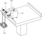
FIG. 1 is a schematic diagram of the overall structure of an embodiment of the present application;
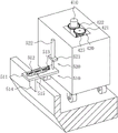
FIG. 2 is a schematic structural diagram of a lifting mechanism in an embodiment of the present application;
figure 3 is a schematic structural view of a securing mechanism in an embodiment of the present application.
Reference numerals: 100. moving the vehicle body; 200. a lifting mechanism; 210. a support plate; 220. a winch; 230. a guide bar; 240. a blocking block; 250. a rotating wheel; 300. an operation platform; 400. a rotating mechanism; 410. rotating the rod; 420. a rotating assembly; 421. a first gear; 422. a second gear; 423. a drive motor; 500. a stabilizing mechanism; 510. a clamping assembly; 511. a connecting plate; 512. a bidirectional lead screw; 513. a hand wheel; 514. a clamping plate; 515. a sliding groove; 520. a drive assembly; 521. a fixing plate; 522. and a hydraulic cylinder.
Detailed Description
The present application is described in further detail below with reference to figures 1-3.
The embodiment of the application discloses bridge overhauls device.
Referring to fig. 1, a bridge maintenance apparatus includes a movable vehicle body 100, a rotating mechanism 400 is mounted on the movable vehicle body 100, a lifting mechanism 200 is mounted on the rotating mechanism 400, the lifting mechanism 200 is connected to a work platform 300, and the lifting mechanism 200 drives the work platform 300 to ascend or descend. When overhauing the bridge, at first will remove automobile body 100 and install on the bridge floor, then install operation platform 300 in one side of bridge through elevating system 200, when the height that meets operation platform 300 is not enough, utilize elevating system 200 drive operation platform 300 to remove, adjust operation platform 300's height, make the constructor on the operation platform 300 can overhaul the bridge at suitable height, reduce constructor and need pedal the rail horizontal pole of stepping on operation platform 300 and overhaul the possibility, promote constructor's security in the maintenance process. The moving vehicle body 100 is mounted with a securing mechanism 500. In the process of detecting the bridge, utilize firm mechanism 500 to carry out the centre gripping to bridge avris guardrail, increase the stability of overhauing the device in the course of the work, improve the suitability of overhauing the device.
Referring to fig. 2 and 3, the rotating mechanism 400 includes a rotating assembly 420, the rotating assembly 420 includes a driving motor 423 fixedly connected above the moving vehicle body 100, a main shaft of the driving motor 423 is vertically disposed, and a first gear 421 is coaxially and fixedly connected to the main shaft of the driving motor 423. The top of removing automobile body 100 rotates and is connected with dwang 410, and the vertical setting of axis of rotation of dwang 410 is gone up coaxial cover and is equipped with second gear 422 to dwang 410, second gear 422 and dwang 410 fixed connection, first gear 421 and second gear 422 meshing connection.
The lifting mechanism 200 comprises a supporting plate 210 horizontally arranged, the supporting plate 210 is located above the moving vehicle body 100, one end of the supporting plate 210 is fixedly connected with a rotating rod 410, one side of the supporting plate 210, away from the moving vehicle body 100, is fixedly connected with two winches 220, the two winches 220 are located close to the positions, away from one end of the rotating rod 410, of the supporting plate 210, a yielding groove is formed in the supporting plate 210, the supporting plate 210 is rotatably connected with two rotating wheels 250, the two rotating wheels 250 and the two winches 220 are arranged in a one-to-one correspondence manner, a steel cable on one winch 220 bypasses the corresponding rotating wheel 250 and then passes through the yielding groove and the operation platform 300, and a steel cable on the other winch 220 bypasses the corresponding rotating wheel 250 and then passes through the yielding groove and the operation platform 300 and is fixedly connected with the operation platform 300. Utilize two hoist engines 220 to rotate simultaneously and drive operation platform 300 lift to adjust operation platform 300's position, make constructor can overhaul the bridge at suitable height. Through top fixed connection driving motor 423 at removal automobile body 100, driving motor 423's main shaft rotates and drives first gear 421 and rotate, first gear 421 rotates and drives rather than meshing second gear 422 and rotate, second gear 422 rotates and drives dwang 410 and rotate, thereby make backup pad 210 and operation platform 300 can use the axis of rotation of dwang 410 to rotate as the center, after with operation platform 300 lifting, drive operation platform 300 through slewing mechanism 400 and remove, the position that makes operation platform 300 can change, thereby make things convenient for constructor's upper and lower, the convenience that the device used is overhauld in the improvement.
Referring to fig. 2, two vertically arranged guide rods 230 penetrate through the support plate 210, the two guide rods 230 are both slidably connected with the support plate 210, the lower ends of the two guide rods 230 are both fixedly connected with the work platform 300, one of the guide rods 230 is located at a position close to one end of the work platform 300, the other guide rod 230 is located at a position close to the other end of the work platform 300, the two guide rods 230 are oppositely arranged, and the upper ends of the two guide rods 230 are both fixedly connected with a blocking block 240. The two guide rods 230 are used for guiding the movement of the work platform 300, so that the possibility of shaking of the work platform 300 in the lifting process is reduced, and the stability of the work platform 300 in the using process is improved.
Referring to fig. 2 and 3, the stabilizing mechanism 500 includes a driving assembly 520, the driving assembly 520 is installed at one side of the moving vehicle body 100, and a clamping assembly 510 is installed on the driving assembly 520.
The driving assembly 520 includes a fixing plate 521, the fixing plate 521 is fixedly connected to one side of the movable body 100, the fixing plate 521 is parallel to the supporting plate 210, and a vertically disposed hydraulic cylinder 522 is fixedly connected to the upper side of the fixing plate 521.
The clamping assembly 510 comprises a connecting plate 511, the connecting plate 511 is arranged in parallel with the fixed plate 521, the connecting plate 511 is located below the fixed plate 521, a piston rod of the hydraulic cylinder 522 penetrates through the fixed plate 521 and then is fixedly connected with the connecting plate 511, a bidirectional screw 512 is rotatably connected above the connecting plate 511, the rotating axis of the bidirectional screw 512 is parallel to the fixed plate 521, and a hand wheel 513 is coaxially and fixedly connected to one end, close to the movable vehicle body 100, of the bidirectional screw 512. The connecting plate 511 is provided with a sliding groove 515 along the length direction of the bidirectional screw 512, the sliding groove 515 is internally connected with two parallel clamping plates 514 in a sliding manner, the two clamping plates 514 are perpendicular to the rotation axis of the bidirectional screw 512, the two clamping plates 514 are in threaded connection with the bidirectional screw 512, and the two clamping plates 514 are respectively positioned at the positions close to the two ends of the bidirectional screw 512. In the process of overhauling the bridge, the piston rod of the hydraulic cylinder 522 is extended to drive the connecting plate 511 to descend, so that the two clamping plates 514 on the connecting plate 511 are respectively moved to two sides of the side baffle of the bridge, the two-way screw 512 is driven to rotate by rotating the hand wheel 513, the two-way screw 512 rotates to drive the two clamping plates 514 to be respectively abutted against two sides of the side guardrail of the bridge, the stability of the overhauling device is improved by utilizing the stabilizing mechanism 500, the possibility of inclination caused by the overweight of the operation platform 300 during overhauling is reduced, and the use safety of the overhauling device is improved.
The implementation principle of the bridge overhauling device in the embodiment of the application is as follows: through installing elevating system 200 on removing automobile body 100, work platform 300 is installed on elevating system 200, when detecting the bridge, at first will remove automobile body 100 and set up on the bridge floor of bridge, then set up work platform 300 in one side of bridge, when meetting work platform 300's height inadequately, utilize elevating system 200 to adjust work platform 300's height, make the constructor on the work platform 300 can overhaul the bridge at suitable height, reduce constructor and need pedal the rail horizontal pole on the work platform 300 and overhaul the possibility, improve the suitability of overhauing the device.
The above embodiments are preferred embodiments of the present application, and the protection scope of the present application is not limited by the above embodiments, so: all equivalent changes made according to the structure, shape and principle of the present application shall be covered by the protection scope of the present application.
Claims (8)
1. The utility model provides a bridge overhauls device which characterized in that: including removing automobile body (100), elevating system (200) and operation platform (300), elevating system (200) are connected remove on automobile body (100), operation platform (300) with elevating system (200) are connected, elevating system (200) drive operation platform (300) are along being close to or keeping away from the direction removal on ground.
2. A bridge inspection and repair set according to claim 1, characterised in that: the lifting mechanism (200) comprises a supporting plate (210) and a winch (220), the supporting plate (210) is connected to the movable vehicle body (100), the supporting plate (210) is parallel to the ground, the winch (220) is fixedly connected to the supporting plate (210), the operation platform (300) is located on one side, close to the ground, of the supporting plate (210), and a steel cable on the winch (220) is fixedly connected with the operation platform (300).
3. A bridge inspection apparatus according to claim 2, wherein: the lifting mechanism (200) further comprises two guide rods (230), the two guide rods (230) penetrate through the supporting plate (210), the two guide rods (230) are perpendicular to the supporting plate (210), the two guide rods (230) are in sliding connection with the supporting plate (210), and the two guide rods (230) are fixedly connected with the operation platform (300).
4. A bridge inspection and repair set according to claim 3, wherein: one ends of the two guide rods (230) far away from the working platform (300) are fixedly connected with blocking blocks (240).
5. A bridge inspection and repair set according to claim 2, in which: remove and be provided with slewing mechanism (400) on automobile body (100), slewing mechanism (400) are including dwang (410) and runner assembly (420), dwang (410) are rotated and are connected on removing automobile body (100), the axis of rotation of dwang (410) with backup pad (210) are perpendicular, backup pad (210) with dwang (410) fixed connection, runner assembly (420) are connected on removing automobile body (100), runner assembly (420) with dwang (410) are connected, runner assembly (420) drive dwang (410) rotate.
6. A bridge inspection device according to claim 5, wherein: the rotating assembly (420) comprises a first gear (421), a second gear (422) and a driving motor (423), the driving motor (423) is fixedly connected to the movable vehicle body (100), the first gear (421) is in transmission connection with the driving motor (423), the second gear (422) is in coaxial fixed connection with the rotating rod (410), and the first gear (421) is in meshing connection with the second gear (422).
7. A bridge inspection and repair set according to claim 2, in which: the movable trolley body (100) is provided with a stabilizing mechanism (500), the stabilizing mechanism (500) comprises a clamping component (510) for clamping a guardrail at the side of the bridge, the clamping assembly (510) comprises a connecting plate (511), a bidirectional screw (512), a hand wheel (513) and two clamping plates (514), the connecting plate (511) is connected with the moving vehicle body (100), the connecting plate (511) is parallel to the supporting plate (210), the bidirectional screw rod (512) is rotatably connected to the connecting plate (511), the hand wheel (513) is fixedly connected to one end of the bidirectional screw rod (512), the two clamping plates (514) are in threaded connection with the bidirectional screw rod (512), the two clamping plates (514) are in sliding connection with the connecting plate (511), the bidirectional screw (512) drives the two clamping plates (514) to move towards or away from each other.
8. A bridge inspection device according to claim 7, wherein: the stabilizing mechanism (500) further comprises a driving assembly (520), the driving assembly (520) comprises a fixing plate (521) and a hydraulic cylinder (522), the fixing plate (521) is fixedly connected to one side of the movable vehicle body (100), the fixing plate (521) is located on one side, close to the supporting plate (210), of the connecting plate (511), the hydraulic cylinder (522) is fixedly connected to the fixing plate (521), a piston rod of the hydraulic cylinder (522) penetrates through the fixing plate (521) and is fixedly connected with the connecting plate (511), and the hydraulic cylinder (522) drives the connecting plate (511) to move in the direction close to or far away from the ground.
Priority Applications (1)
| Application Number | Priority Date | Filing Date | Title |
|---|---|---|---|
| CN202220428257.7U CN216838978U (en) | 2022-02-28 | 2022-02-28 | Bridge overhauls device |
Applications Claiming Priority (1)
| Application Number | Priority Date | Filing Date | Title |
|---|---|---|---|
| CN202220428257.7U CN216838978U (en) | 2022-02-28 | 2022-02-28 | Bridge overhauls device |
Publications (1)
| Publication Number | Publication Date |
|---|---|
| CN216838978U true CN216838978U (en) | 2022-06-28 |
Family
ID=82092644
Family Applications (1)
| Application Number | Title | Priority Date | Filing Date |
|---|---|---|---|
| CN202220428257.7U Active CN216838978U (en) | 2022-02-28 | 2022-02-28 | Bridge overhauls device |
Country Status (1)
| Country | Link |
|---|---|
| CN (1) | CN216838978U (en) |
-
2022
- 2022-02-28 CN CN202220428257.7U patent/CN216838978U/en active Active
Similar Documents
| Publication | Publication Date | Title |
|---|---|---|
| CN107419625B (en) | Full-automatic numerical control hydraulic turnout tamping car | |
| CN111661764B (en) | High wheeled hoist of security | |
| CN205933122U (en) | Flexible rotation type operation arm and contact net operation platform truck of contact net operation platform truck | |
| CN115596463A (en) | Arch frame installation device for repairing operated tunnel defects | |
| CN216838978U (en) | Bridge overhauls device | |
| CN2310087Y (en) | Tower and cable overhaul vehicle for suspension bridge | |
| CN211998698U (en) | Contact net tunnel davit mounting platform | |
| CN107386138B (en) | Totally-enclosed sound insulation screen construction vehicle and totally-enclosed sound insulation screen installation method | |
| CN213202132U (en) | Crane capable of being moved lightly | |
| CN216737394U (en) | Generator guide bush hoisting accessory | |
| CN211366844U (en) | Engineering vehicle support oil cylinder lifting device | |
| CN212076191U (en) | Special beam lifting machine for intercity light rail | |
| CN114370241A (en) | Vehicle-mounted full-hydraulic workover rig | |
| CN210341634U (en) | Viaduct outer wall painting crane | |
| CN109403707B (en) | V-shaped framework hoisting construction auxiliary equipment and construction method | |
| CN112429677A (en) | Steel formwork installation device and method suitable for cover plate | |
| CN218988622U (en) | Lifting equipment for drilling tool at drilling well site | |
| CN112707337A (en) | Engineering vehicle landing leg hydro-cylinder overhead hoist | |
| CN202467697U (en) | Casing stabbing board | |
| CN219450465U (en) | Prestress tensioning device for bridge | |
| CN111764613A (en) | High-altitude equipment installation device in rail traveling area of rail transit engineering and construction method | |
| CN218261666U (en) | Portal device is used in large-scale equipment hoist and mount | |
| CN116040504A (en) | Portable girder steel hoist and mount mechanism | |
| CN219860280U (en) | Pin row installation auxiliary device | |
| CN220300198U (en) | A portable portal crane for hoisting emergency operation device |
Legal Events
| Date | Code | Title | Description |
|---|---|---|---|
| GR01 | Patent grant | ||
| GR01 | Patent grant |