CN216774363U - Multifunctional emergency power supply - Google Patents
Multifunctional emergency power supply Download PDFInfo
- Publication number
- CN216774363U CN216774363U CN202220165880.8U CN202220165880U CN216774363U CN 216774363 U CN216774363 U CN 216774363U CN 202220165880 U CN202220165880 U CN 202220165880U CN 216774363 U CN216774363 U CN 216774363U
- Authority
- CN
- China
- Prior art keywords
- power supply
- positioning
- casing
- multifunctional emergency
- shell
- Prior art date
- Legal status (The legal status is an assumption and is not a legal conclusion. Google has not performed a legal analysis and makes no representation as to the accuracy of the status listed.)
- Active
Links
Images


Landscapes
- Charge And Discharge Circuits For Batteries Or The Like (AREA)
Abstract
The utility model provides a multifunctional emergency power supply, which comprises a shell and a lighting power supply device arranged in the shell, wherein the shell is formed by assembling two shells, and meanwhile, collision-proof angles are respectively arranged at the top corners of the shells, so that the damage caused by falling of the emergency power supply can be effectively reduced, the service life is prolonged, meanwhile, the power supply is provided with various power supply interfaces, various electronic equipment can be charged, and meanwhile, the power supply can carry out electrification service on vehicles, can realize various lighting modes, and especially can improve the self-rescue capability of trapped people at night.
Description
Technical Field
The utility model relates to the technical field of emergency power equipment, in particular to a multifunctional emergency power supply.
Background
The vehicle-mounted storage battery is used for providing power energy for vehicle ignition, vehicle lamps and various electronic devices, and the storage battery is charged by the engine in the driving process of the vehicle, so that the storage battery can continuously supply power to the electric equipment on the vehicle.
However, when the vehicle is parked for a long time or the battery is short of power due to forgetting to turn off the electronic equipment or the lamp by the carelessness of the driver, the vehicle cannot be started, and when the situation occurs, other power supplies need to be temporarily connected onto the battery of the vehicle, and then the vehicle is started.
SUMMERY OF THE UTILITY MODEL
Aiming at the problems in the prior art, the utility model provides a multifunctional emergency power supply which can provide starting electric energy for a vehicle and has the functions of light warning and long-term illumination.
The utility model is realized by the following technical scheme:
a multifunctional emergency power supply comprises a power supply shell and a lighting power supply device arranged in the power supply shell;
the power supply casing includes the casing, control panel and crashproof angle down, casing and casing fixed connection down, and inside vacuole formation, the vertex angle department of the arc type of crashproof angle setting at the power supply casing, the light-passing board has been set to the surface of going up the casing, illumination power supply unit fixes in the cavity and just to the light-passing board, the control panel integrated circuit board connects the one side at the power supply casing, the last multiple power supply interface that is provided with of control panel, power supply interface is connected with illumination power supply unit, illumination power supply unit is used for providing the illumination and supplies power to power supply interface.
Preferably, the surface of the vertex angle of the power supply shell and the surface of the shell form a concave step surface, and the collision-proof angle is coated on the vertex angle and is clamped with the step surface.
Preferably, a plurality of clamping grooves are formed in the splicing positions of the edges of the top corners and the step surfaces, and clamping blocks matched with the clamping grooves are arranged on the anti-collision corners.
Preferably, the control panel is provided with a USB interface, a typec interface and a binding post for supplying power to the vehicle.
Preferably, the control panel is further provided with a cover plate capable of being opened and closed, and the cover plate is used for covering the power supply interface area.
Preferably, the power supply shell is further provided with a back plate, and the back plate is located on the rear side of the box body and is parallel to the control panel.
Preferably, be provided with a plurality of locating pieces and trip on the inner wall of the upper and lower edge of backplate, the both sides of backplate are provided with the side locating piece that extends to the outside, go up the edge of casing and lower casing mounting groove and be provided with locating piece and trip complex constant head tank and draw-in groove, the side locating piece is located the concatenation department of casing and lower casing to with the inner wall butt of casing, locating piece and trip are connected with constant head tank and draw-in groove cooperation respectively.
Preferably, a handle is arranged on the power supply shell, and an angle adjusting device is arranged on the handle and the power supply shell and used for adjusting the angle of the power supply shell.
Preferably, the angle adjusting device comprises a positioning column and a positioning tooth;
the power supply comprises a power supply shell and is characterized in that mounting holes are formed in two sides of the power supply shell, positioning teeth are evenly distributed on the circumference of the inner wall of each mounting hole, positioning rings extending towards the direction of the shell are respectively arranged at two ends of each handle, positioning columns are arranged on the side walls of the positioning rings, the positioning rings are located in the mounting holes and in clearance fit with the mounting holes, and the positioning columns are located in tooth grooves of two adjacent positioning teeth.
Preferably, the illumination power supply unit includes reflector, circuit board, integrated light source and battery, and the battery is fixed on casing down, and integrated light source sets up the top surface at the battery, and the reflector shines at integrated light source's luminous region, and the upper end and the light-passing board sealing connection of reflector, integrated light source and battery are connected with the circuit board respectively, and the circuit board is connected with power supply interface.
Compared with the prior art, the utility model has the following beneficial technical effects:
the utility model provides a multifunctional emergency power supply, which comprises a shell and a lighting power supply device arranged in the shell, wherein the shell is formed by assembling two shells, and meanwhile, collision-proof angles are respectively arranged at the top corners of the shells, so that the damage caused by falling of the emergency power supply can be effectively reduced, the service life is prolonged, meanwhile, the power supply is provided with various power supply interfaces, various electronic equipment can be charged, and meanwhile, the power supply can carry out electrification service on vehicles, can realize various lighting modes, and especially can improve the self-rescue capability of trapped people at night.
Drawings
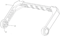
FIG. 1 is a schematic diagram of an external view of a multifunctional emergency power supply according to the present invention;
FIG. 2 is a schematic diagram of an external structure of the power supply body according to the present invention;
FIG. 3 is a schematic view of the installation of the lower case and the anti-collision corner of the power supply of the present invention;
FIG. 4 is an exploded view of the power supply housing of the present invention;
FIG. 5 is an enlarged view of the impact corner of the present invention;
FIG. 6 is a schematic view of a handle according to the present invention;
FIG. 7 is a schematic structural diagram of a back plate according to the present invention;
FIG. 8 is a schematic structural diagram of a control panel according to the present invention;
FIG. 9 is a schematic diagram of the circuit interface on the control panel according to the present invention;
FIG. 10 is a schematic view of the structure of the lighting device of the present invention;
fig. 11 is an exploded view of the lighting device of the present invention.
In the figure: 1. an upper housing; 2. a lower housing; 4. positioning teeth; 5. an anti-collision angle; 6. a control panel; 7. a cover plate; 8. a back plate; 9. a light-transmitting plate; 10. a card slot; 11. a handle; 12. a fixing pin; 13. a positioning column; 14. a reflector; 15. a circuit board; 16. a COB integrated light source; 17. a battery; 81. positioning blocks; 82. a hook is clamped; 83. and (6) side positioning blocks.
Detailed Description
The present invention will now be described in further detail with reference to the attached drawings, which are illustrative, but not limiting, of the present invention.
Referring to fig. 1-11, a multifunctional emergency power supply comprises a power supply body and a handle 11 connected with the power supply body, wherein the power supply body comprises a power supply shell and a lighting power supply device arranged in the power supply shell;
the power supply casing includes casing 1, casing 2 down, control panel 6 and crashproof angle 5, casing 2 and casing fixed connection down, and inside vacuole formation, crashproof angle 5 sets up the apex angle department at the circular arc type of power supply casing, the surface of going up casing 1 has inlayed light-passing board 9, illumination power supply unit fixes in the cavity and just to light- passing board 9, 6 joints of control panel are in one side of power supply casing, be provided with multiple power supply interface on the control panel 6, power supply interface is connected with illumination power supply unit, illumination power supply unit is used for providing the illumination and provides the electric energy to power supply interface.
The surface of power casing arc apex angle and the step face of casing surface formation indent, crashproof angle 5 cladding on the apex angle and with step face joint, the crashproof angle adopts rubber materials to make, because rubber has good elasticity, consequently at four apex angle cladding rubber of power casing, simultaneously through the research, the power body is owing to adopt the rectangle structure, consequently the apex angle and the ground contact of power casing basically after falling, adopt crashproof angle 5 cladding back, it at first contacts with ground to fall back crashproof angle 5, that is to say, rubber and ground contact, because the resilience compressive property of rubber, can play the cushioning effect to the power casing, reduce the inside illumination power supply unit of impact protection power casing.
The edge at arc apex angle is provided with a plurality of draw-in grooves 10 with the concatenation department of step face, is provided with draw-in groove complex fixture block on crashproof angle 5, and crashproof angle 5 and apex angle joint design dismantlement when being convenient for maintain like this, simultaneously, go up the casing and adopt bolted connection with lower casing, and the bolt setting is in the apex angle position, and crashproof angle 5 will be connected the back with the apex angle, covers the bolt hole, avoids water to get into the bolt hole and improves the aesthetic property of whole power simultaneously.
8-10, all set up the mounting groove that is used for installing control panel 6 on upper casing and the lower casing, control panel 6 and mounting groove joint, control panel 6 is last to be provided with the USB interface, type interface, the terminal that is used for supplying power for the vehicle, and power starting switch, through a plurality of interfaces, this emergency power supply not only can realize rescuing the vehicle, can supply power for cell-phone and all kinds of electronic product simultaneously, during the use, start switch, with electronic equipment and USB interface or type interface, realize charging temporarily, avoid getting into the dust at idle state power supply interface, still be provided with the apron on control panel 6 for protect the power supply interface.
Still be provided with backplate 8 on the power casing, backplate 8 is located the rear side of box and with control panel parallel arrangement, and the both sides of casing are provided with the mounting groove respectively under like this, the illumination power supply unit's of being convenient for installation and debugging, and control panel and backplate are the same with the mounting means of last casing and lower casing, and consequently control panel and backplate are the same in structure, all adopt the mode of joint to connect, use the backplate to carry out detailed explanation to the structure of control panel and backplate as the example below.
Referring to fig. 7 and 8, a plurality of positioning blocks 81 and hooks are arranged on the inner walls of the upper edge and the lower edge of the back plate, side positioning blocks 83 extending towards the outside are arranged on the two sides of the back plate, the positioning blocks 81 and the hooks are alternately arranged at intervals, positioning blocks 81 and hooks are arranged on the edges of the upper shell and the lower shell mounting groove, the positioning blocks 81 and the hooks are matched with positioning grooves and clamping grooves, the side positioning blocks 83 are located at the splicing positions of the upper shell and the lower shell and are abutted against the inner walls of the shells, and the positioning blocks 81 and the hooks are matched with the positioning grooves and the clamping grooves respectively and connected with the positioning grooves and the clamping grooves.
Go up the concatenation department of casing and lower casing both sides and be provided with the handle mounting hole, be formed with the collar that extends to the outside on the mounting hole, the inside circumference equipartition of collar has location tooth 4, handle 11 wholly is U type structure, and its both ends are provided with the holding ring that extends to the casing direction respectively, are provided with reference column 13 on the lateral wall of holding ring, and the holding ring is located the collar and clearance fit, and reference column 13 is located the tooth's socket of two adjacent location teeth, is provided with inflation formula reference column 13 in mounting hole and the holding ring, and the handle passes through reference column 13 and is connected with the casing, rotates the handle and makes the reference column be located different tooth's sockets through the deformation of holding ring, realizes placing of the different angles of power body, and the handle plays the supporting role simultaneously, adjusts the angle of shining of fluorescent tube.
The lighting power supply device comprises a reflecting cover 14, a circuit board 15, an integrated light source 16 and a battery 17, wherein the battery 17 is fixed on the lower shell, the integrated light source 16 is arranged on the top surface of the battery, the reflecting cover 14 irradiates a light emitting area of the integrated light source 16, the upper end of the reflecting cover is hermetically connected with the light transmitting plate 9, the integrated light source 16 and the battery are respectively connected with the circuit board 15, and the circuit board 15 is connected with a power supply interface.
The reflector 14 is the open structure of rectangle, and the inner wall of reflector 14 is the light reflecting area, and the tip and the integrated light source 16 of reflector 14 are connected, and the light that integrated light source 16 transmitted can improve illumination luminance by a wide margin through the light reflecting area, especially uses the illuminating effect better outstanding night.
The two sides of the reflector 14 are respectively provided with a PCB board, the PCB board is provided with a plurality of SMD mounted devices, and the SMD mounted devices 142 have high reliability and strong shock resistance, and reduce electromagnetic and radio frequency interference. Integrated light source 16 adopts the COB light source, but COB integrated light source independent assortment forms multiple LED light effect. In this embodiment, there are four kinds of lamp-off effects in common, the spotlight is high bright, the spotlight is low bright, the astigmatism and the red-white light flicker alternately to form the alarm lamp effect, and through adjusting the switch according to the lamp-off mode, the four kinds of effect modes alternate in sequence, and the lamp-off mode is adjusted the switch once triggered, and then a kind of light mode is changed.
The solar cell module is characterized in that a solar panel is arranged on the surface of the lower shell and used for charging a battery, a plurality of solar cells are arranged on the solar panel, and the solar cells are single crystals or polycrystal. The solar cell is preferably a single crystal solar panel with the voltage of 6V and the power of 1W, so that the charging conversion efficiency is high.
The upper shell and the lower shell are both made of engineering plastics ABS, and the ABS has high toughness and strength, is anticorrosive, and has a mature processing technology.
In the description of the present invention, it is to be understood that the terms "inside", "upper surface", "upper", and the like indicate orientations or positional relationships based on those shown in the drawings, and are only for convenience in describing the present invention and simplifying the description, but do not indicate or imply that the referred unit or element must have a specific orientation, be constructed in a specific orientation, and be operated, and thus, should not be construed as limiting the present invention.
In the present invention, unless otherwise expressly stated or limited, the terms "mounted," "provided," "connected," and the like are to be construed broadly, e.g., as meaning fixedly connected, detachably connected, or integral to; they may be mechanically or electrically connected, directly or indirectly through intervening media, or may be interconnected between two elements or in an interactive relationship between two elements unless expressly stated otherwise. The specific meanings of the above terms in the present invention can be understood by those skilled in the art according to specific situations.
While preferred embodiments of the present application have been described, additional variations and modifications of these embodiments may occur to those skilled in the art once they learn of the basic inventive concepts. Therefore, it is intended that the appended claims be interpreted as including the preferred embodiment and all such alterations and modifications as fall within the true scope of the embodiments of the application.
Finally, it should also be noted that, in this document, the terms "comprises," "comprising," or any other variation thereof, are intended to cover a non-exclusive inclusion, such that a process, method, article, or terminal that comprises a list of elements does not include only those elements but may include other elements not expressly listed or inherent to such process, method, article, or terminal. The word "comprising", without further limitation, does not exclude the presence of other identical elements in the process, method, article, or terminal device in which the word is used.
The multifunctional emergency power supply provided by the application is described in detail above, and a specific example is applied in the description to explain the principle and the implementation of the application, and the description of the above embodiment is only used to help understanding the method and the core idea of the application; meanwhile, for a person skilled in the art, according to the idea of the present application, there may be variations in the specific embodiments and application ranges, and in summary, the above contents are only for illustrating the technical idea of the present invention, and the protection range of the present invention is not limited thereby, and any modifications made on the basis of the technical solution according to the technical idea proposed by the present invention fall within the protection range of the claims of the present invention.
Claims (10)
1. A multifunctional emergency power supply is characterized by comprising a power supply shell and a lighting power supply device arranged in the power supply shell;
the power supply casing includes casing (1), casing (2) down, control panel (6) and crashproof angle (5), casing (2) and casing fixed connection down, and inside vacuole formation, crashproof angle (5) set up the apex angle department at the circular arc type of power supply casing, the surface of going up casing (1) has set up light-passing board (9), illumination power supply unit fixes in the cavity and just to light-passing board (9), control panel (6) joint is in one side of power supply casing, be provided with multiple power supply interface on control panel (6), the power supply interface is connected with illumination power supply unit, illumination power supply unit is used for providing the illumination and supplies power to the power supply interface.
2. The multifunctional emergency power supply of claim 1, wherein the surface of the top corner of the power supply housing and the surface of the housing form a concave step surface, and the anti-collision corner (5) is coated on the top corner and clamped with the step surface.
3. The multifunctional emergency power supply according to claim 2, wherein a plurality of clamping grooves (10) are formed in the splicing position of the edge of the top corner and the step surface, and clamping blocks matched with the clamping grooves are arranged on the anti-collision corners (5).
4. Multifunctional emergency power supply according to claim 1, characterized in that the control panel (6) is provided with a USB interface, a typec interface and terminals for powering the vehicle.
5. Multifunctional emergency power supply according to claim 4, characterized in that the control panel (6) is further provided with a cover plate capable of opening and closing for covering the power supply interface area.
6. The multifunctional emergency power supply of claim 1, wherein the power supply housing is further provided with a back plate (8), and the back plate (8) is located at the rear side of the box body and is parallel to the control panel.
7. The multifunctional emergency power supply according to claim 6, wherein a plurality of positioning blocks (81) and hooks are disposed on inner walls of upper and lower edges of the back plate, side positioning blocks (83) extending outward are disposed on two sides of the back plate, positioning grooves and locking grooves for the positioning blocks (81) and the hooks to engage are disposed on edges of the mounting grooves of the upper and lower housings, the side positioning blocks (83) are disposed at a joint of the upper and lower housings and abut against the inner walls of the housings, and the positioning blocks (81) and the hooks are respectively connected with the positioning grooves and the locking grooves in an engaging manner.
8. The multifunctional emergency power supply according to claim 6, wherein a handle (11) is provided on the power supply housing, and an angle adjusting device is provided on the handle (11) and the power supply housing for adjusting the angle of the power supply housing.
9. Multifunctional emergency power supply according to claim 8, characterized in that said angular adjustment means comprise a positioning post (13) and a positioning tooth;
the power supply comprises a power supply shell and is characterized in that mounting holes are formed in two sides of the power supply shell, positioning teeth (4) are evenly distributed on the circumference of the inner wall of each mounting hole, positioning rings extending towards the direction of the shell are arranged at two ends of each handle respectively, positioning columns (13) are arranged on the side walls of the positioning rings, the positioning rings are located in the mounting holes and in clearance fit, and the positioning columns (13) are located in tooth grooves of two adjacent positioning teeth.
10. The multifunctional emergency power supply of claim 1, wherein the lighting power supply device comprises a reflector (14), a circuit board (15), an integrated light source (16) and a battery (17), the battery (17) is fixed on the lower casing, the integrated light source (16) is arranged on the top surface of the battery, the reflector (14) irradiates a light emitting area of the integrated light source (16), the upper end of the reflector is hermetically connected with the light-transmitting plate (9), the integrated light source (16) and the battery are respectively connected with the circuit board (15), and the circuit board (15) is connected with the power supply interface.
Priority Applications (1)
| Application Number | Priority Date | Filing Date | Title |
|---|---|---|---|
| CN202220165880.8U CN216774363U (en) | 2022-01-21 | 2022-01-21 | Multifunctional emergency power supply |
Applications Claiming Priority (1)
| Application Number | Priority Date | Filing Date | Title |
|---|---|---|---|
| CN202220165880.8U CN216774363U (en) | 2022-01-21 | 2022-01-21 | Multifunctional emergency power supply |
Publications (1)
| Publication Number | Publication Date |
|---|---|
| CN216774363U true CN216774363U (en) | 2022-06-17 |
Family
ID=81978678
Family Applications (1)
| Application Number | Title | Priority Date | Filing Date |
|---|---|---|---|
| CN202220165880.8U Active CN216774363U (en) | 2022-01-21 | 2022-01-21 | Multifunctional emergency power supply |
Country Status (1)
| Country | Link |
|---|---|
| CN (1) | CN216774363U (en) |
-
2022
- 2022-01-21 CN CN202220165880.8U patent/CN216774363U/en active Active
Similar Documents
| Publication | Publication Date | Title |
|---|---|---|
| US5797672A (en) | Safety light | |
| CN200996563Y (en) | Anti-battery-mechanized electric torch | |
| CN216774363U (en) | Multifunctional emergency power supply | |
| CN208652256U (en) | Wide-angle type wall lamp | |
| CN212617838U (en) | LED street lamp | |
| CN212080897U (en) | Straight tube type LED lamp with plug type module box | |
| CN113586977A (en) | Portable lamp | |
| CN208846297U (en) | A kind of emergency lighting and the compound lamps and lanterns of exit signs | |
| CN214425870U (en) | Invisible solar monitoring projection lamp | |
| CN211345076U (en) | General type plastic LED ceiling lamp | |
| CN205402316U (en) | Novel explosion -proof folding straight board lamp of rechargeable portable LED | |
| CN2845042Y (en) | Warning lamp | |
| CN212303826U (en) | Battery module and solar lamp that can conveniently install and remove | |
| CN212840810U (en) | Multifunctional small night lamp | |
| CN216215954U (en) | Charger with small night lamp | |
| CN218237147U (en) | Outdoor lamp | |
| CN217737086U (en) | Novel solar ceiling lamp | |
| CN218119607U (en) | Solar bulb | |
| CN210128259U (en) | Strip-shaped lamp and strip-shaped lamp combination | |
| CN218469005U (en) | Multi-head solar lighting device | |
| CN212298805U (en) | Plug-pull safety protection structure of solar lamp | |
| CN215597074U (en) | Portable lamp | |
| CN214147679U (en) | But LED industrial and mining lamp of quick replacement power | |
| CN217603992U (en) | Solar lamp | |
| CN212960939U (en) | Emergency LED tri-proof light |
Legal Events
| Date | Code | Title | Description |
|---|---|---|---|
| GR01 | Patent grant | ||
| GR01 | Patent grant |