CN216730477U - Automatic assembly quality of high-efficient pressfitting of tube spindle subassembly - Google Patents
Automatic assembly quality of high-efficient pressfitting of tube spindle subassembly Download PDFInfo
- Publication number
- CN216730477U CN216730477U CN202122894816.1U CN202122894816U CN216730477U CN 216730477 U CN216730477 U CN 216730477U CN 202122894816 U CN202122894816 U CN 202122894816U CN 216730477 U CN216730477 U CN 216730477U
- Authority
- CN
- China
- Prior art keywords
- cylinder
- pipe shaft
- pedal
- press
- fixed
- Prior art date
- Legal status (The legal status is an assumption and is not a legal conclusion. Google has not performed a legal analysis and makes no representation as to the accuracy of the status listed.)
- Active
Links
Images


Landscapes
- Automatic Assembly (AREA)
Abstract
The utility model discloses an automatic assembly device for efficient pressing of a pipe shaft assembly, which comprises a workbench, wherein a pipe shaft feeding device, a pipe shaft taking and transferring mechanism, a pipe shaft assembly mechanism, a pedal placing tool, a fixing ring pressing-in mechanism and a fixing ring taking and transferring mechanism are sequentially arranged on the workbench; the pedal placing tool is arranged on one side perpendicular to the press-fitting direction of the tubular shaft assembling mechanism, the pedal seat is fixed on the pedal placing tool, and the pedal placing tool is connected with the workbench in a sliding mode along the pedal feeding direction; the fixing ring press-in mechanism and the tubular shaft assembling mechanism are arranged in parallel, the utility model adopts a mode that the air cylinder is matched with the slide rail, and the guide and limiting structure is arranged, thereby improving the assembling precision and efficiency, ensuring the production safety and avoiding the damage to the product.
Description
Technical Field
The utility model relates to the technical field of pipe shaft assembly, in particular to an automatic assembly device for efficient pressing of a pipe shaft assembly.
Background
With the rapid development of modern industries, the automobile industry becomes an important pillar industry, and the assembly of automobile parts also enters a rapid development era. Whether the assembly of every spare part of car correctly concerns the security of future in the driving, especially involve the brake accelerator pedal module mechanism that the vehicle went to stop, this mechanism all adopts the manual work to assemble spare part one by one before, and the manual assembly is inefficient, must have the problem that the error rate is high simultaneously, and the manual work can appear when the part is impressed in the assembly, impresses not in place, leads to the product unqualified, and the rework rate is high to and the problem such as cost of labor height.
SUMMERY OF THE UTILITY MODEL
The technical purpose is as follows: the utility model discloses an automatic assembling device for efficient pressing of a tubular shaft assembly, which is high in production efficiency and capable of efficiently pressing a pedal and a tubular shaft, aiming at the defects that the existing vehicle brake and accelerator pedal is low in assembling efficiency and high in rework rate.
The technical scheme is as follows: in order to achieve the technical purpose, the utility model adopts the following technical scheme:
an automatic assembly device for efficient pressing of a pipe shaft assembly comprises the pipe shaft, a pedal and a fixing ring, wherein the pipe shaft is arranged on a pedal seat in a penetrating mode, the pedal is sleeved outside the pipe shaft in an outer sleeved mode, the fixing ring is located at the end portion of the pipe shaft and used for fixing the pipe shaft and the pedal seat, and the fixing ring is characterized by comprising a workbench; the pedal placing tool is arranged on one side perpendicular to the press-fitting direction of the tubular shaft assembling mechanism, the pedal seat is fixed on the pedal placing tool, and the pedal placing tool is connected with the workbench in a sliding mode along the pedal feeding direction; and the fixing ring press-in mechanism is arranged in parallel with the tubular shaft assembling mechanism, and after the tubular shaft is assembled, the fixing ring is pressed into the end part of the tubular shaft to fix the tubular shaft and the pedal seat.
Preferably, the pipe shaft assembling mechanism of the utility model comprises a pipe shaft guide assembly for assisting penetration of the pipe shaft, a tubular shaft pressing-in component for penetrating the tubular shaft into the pedal seat and the pedal and a pedal mounting and positioning component for press-fitting and positioning the pedal before the tubular shaft is pressed in, wherein the tubular shaft guiding component comprises two first supporting plates which are oppositely arranged on the workbench, a first mounting plate is arranged above the first supporting plate and is connected with the upper end of the first supporting plate in a sliding way along the assembly direction of the pipe shaft, a first cylinder for driving the first mounting plate to slide is arranged on one side of the first supporting plate, a guide positioning block corresponding to a pipe shaft mounting hole on the pedal seat is arranged at one end of the first mounting plate close to the pedal seat, a guide rod penetrates through the guide positioning block, and a first sliding table cylinder for driving the guide rod to move is arranged above the first mounting plate; according to the utility model, the limiting block is arranged below the first mounting plate, the first limiting cylinder is arranged below the limiting block, the first limiting cylinder is vertically arranged, the driving end is upward, and the first limiting cylinder blocks the limiting block after the first mounting plate is moved in place.
Preferably, the pedal mounting and positioning assembly comprises a second sliding table cylinder arranged in parallel with the first sliding table cylinder, a second mounting plate is fixed at the driving end of the second sliding table cylinder, and a profiling guide piece arranged in a profiling way with the cross section of the pedal is arranged at the end part of the second mounting plate; the pedal device comprises a pedal, a first sliding table cylinder, a second sliding table cylinder, a third sliding table cylinder, a fourth sliding table cylinder, a copying press block and a copying guide piece, wherein the third sliding table cylinder is arranged in the direction perpendicular to the second sliding table cylinder, the fourth sliding table cylinder is fixed at the driving end of the third sliding table cylinder, the fourth sliding table cylinder is vertically arranged on the third sliding table cylinder, the copying press block with the end matched with the edge shape of the pedal is fixed at the driving end of the fourth sliding table cylinder, and after the pedal is placed in, the copying press block is matched with the copying guide piece to fix the angle and the position of the pedal.
Preferably, the tubular shaft press-in assembly of the present invention comprises two second support plates arranged oppositely, a third mounting plate is slidably connected above the two second support plates, a mounting block is fixed on the third mounting plate, a tubular shaft mounting pin for tubular shaft mounting is arranged on one side of the mounting block close to the guide rod, error-proof guide pieces are arranged on the two sides of the tubular shaft mounting pin by the mounting block, and the mounting direction of the tubular shaft is confirmed by the error-proof guide pieces; and a press-fitting cylinder for driving the third mounting plate to slide on the second support plate along the assembling direction is arranged below the third mounting plate, the press-fitting cylinder is fixed on the second support plate, and the driving end of the press-fitting cylinder is fixedly connected with the third mounting plate through a first connecting block to drive the third mounting plate to slide.
Preferably, a sensor for detecting the pipe shaft is arranged on one side of the pipe shaft pressing-in assembly, the sensor is fixed on the workbench through a mounting support rod, and the sensor is electrically connected with the press-fitting cylinder.
Preferably, the fixing ring press-in mechanism comprises limiting assemblies symmetrically arranged on two sides of the pedal seat; set up the tight subassembly in hollow shaft top that is used for the tight restriction circumferential displacement in hollow shaft tip top on one of them spacing subassembly, set up the solid fixed ring subassembly of impressing that is used for solid fixed ring to impress on another spacing subassembly, spacing subassembly includes the base, is equipped with the third backup pad of two relative settings on the base, all sets up the spacing cylinder of a second in every third backup pad, and the spacing cylinder end fixing of second has the stopper that passes third backup pad face.
Preferably, the tubular shaft jacking assembly comprises a jacking cylinder, a fourth mounting plate and a mandril, wherein the fourth mounting plate is fixed at the driving end of the jacking cylinder and is in sliding connection with the limiting assembly in the direction parallel to the tubular shaft;
the fixing ring press-in assembly comprises a press-in bracket and a servo cylinder, a fifth sliding table cylinder for driving the press-in bracket to integrally move is arranged below the press-in bracket, a fifth mounting plate is fixed at the driving end of the fifth sliding table cylinder, a pressure head fixing seat is arranged at the front end of the press-in support of the fifth mounting plate, the pressure head fixing seat is connected with the fifth mounting plate in a sliding manner along the direction vertical to the pipe shaft, a pressure head for fixing the pressing of the ring and a spare pressure head for replacing the damaged pressure head are arranged on a pressure head fixing seat, a servo cylinder is fixed on a pressing-in support, a push rod of the servo cylinder passes through the pressing-in support and then just faces to one side of a tubular shaft, the pressure head and the spare pressure head both pass through the pressure head fixing seat and are matched with the push rod of the servo cylinder through a pressing block, the push rod pushes the pressure head to slide on the pressure head fixing seat, and the end parts of the pressure head and the spare pressure head, which are close to one side of the tubular shaft, are respectively provided with a magnet for adsorbing the fixing ring.
Preferably, the pedal placing tool comprises a bottom plate which is in sliding connection with a workbench along a direction perpendicular to the installation direction of a tubular shaft, a third rodless cylinder parallel to the sliding direction is arranged on one side of the bottom plate, the bottom plate is connected with the driving end of the third rodless cylinder, a tool plate for fixing a pedal seat is arranged on the bottom plate, the tool plate is in sliding connection with the bottom plate along a direction parallel to the axis of the tubular shaft, spring plungers are arranged at two ends of the sliding direction of the tool plate and fixed on the bottom plate through a fixing support, a positioning block designed according to the shape of the pedal seat and a locking cylinder located on one side of the tool plate and used for compressing and fixing a product are arranged above the tool plate, a polyurethane pressing block is fixed at the driving end of the locking cylinder, and the polyurethane pressing block is compressed by the locking cylinder after the position of the pedal seat is adjusted to be in place; and a third sensor electrically connected with the locking cylinder is arranged on the tooling plate, and whether a product is placed on the tooling plate or not is detected through the third sensor.
Preferably, the pipe shaft taking and transferring mechanism comprises a support frame fixed on a workbench, a rodless cylinder is horizontally fixed on the support frame, a sixth sliding table cylinder is fixed at the driving end of the rodless cylinder, the sixth sliding table cylinder is vertically arranged, and a pneumatic clamp for clamping a pipe shaft is arranged at the driving end of the sixth sliding table cylinder; and a seventh sliding table cylinder parallel to the rodless cylinder is arranged on one side of the support frame, an eighth sliding table cylinder vertical to the sliding direction of the seventh sliding table cylinder is arranged at the driving end of the seventh sliding table cylinder, a swing pneumatic claw is installed at the driving end of the eighth sliding table cylinder, the swing pneumatic claw receives a pipe shaft on the pneumatic fixture, and the pipe shaft is placed on the pipe shaft assembling mechanism by rotating 90 degrees.
Preferably, the fixed ring workpiece taking and transferring mechanism comprises a fixed support, a ninth sliding table cylinder is vertically arranged on the fixed support, and a workpiece connecting tool is fixed at the driving end of the ninth sliding table cylinder; set up the no pole cylinder of second in the below of union piece frock, the fixed subassembly of transporting of drive end of the no pole cylinder of second, it includes linking bridge to transport the subassembly, sliding connection between linking bridge lower part and the workstation, set up tenth slip table cylinder above the linking bridge, the slip direction of tenth slip table cylinder drive end is perpendicular with the moving direction of the no pole cylinder of second, set up the clamping jaw cylinder that is used for pressing from the union piece frock clamp to get solid fixed ring at the drive end of tenth slip table cylinder, clamping jaw cylinder presss from both sides and gets solid fixed ring back, it puts solid fixed ring on solid fixed ring mechanism of impressing through the drive of no pole cylinder of second and carries out the pressure equipment.
Has the advantages that: the automatic assembling device for efficient pressing of the pipe shaft assembly provided by the utility model has the following beneficial effects:
1. the utility model utilizes the combination of the slide rail and the cylinder to improve the assembly accuracy, and the fixed ring taking and transferring mechanism and the tubular shaft taking and transferring mechanism which are arranged side by side can save space, save production cost and improve the assembly production efficiency.
2. The tubular shaft guide assembly is provided with the limiting cylinder and the limiting block, so that springback in the guide process can be avoided, the fixing ring pressing-in mechanism is also arranged to be absorbed as an assembly, the operation reliability of equipment is improved, and the press-fitting qualified rate is ensured.
3. The guide rod is used for guiding the tubular shaft in the penetrating process, and the guide positioning block is matched, so that the product and the guide rod are prevented from being collided due to dislocation.
4. According to the utility model, the pedal installation positioning assembly is arranged, the pedal installation process is guided through the profiling guide piece, and the profiling guide piece is pushed by the air cylinder to compress the pedal, so that the pedal can be accurately positioned, and the product assembly qualification rate is improved.
Drawings
In order to more clearly illustrate the embodiments of the present invention or the technical solutions in the prior art, the drawings used in the description of the embodiments or the prior art will be briefly described below.
FIG. 1 is an overall structural view of the present invention;
FIG. 2 is a structural view of a tubular shaft taking and transferring mechanism of the present invention;
FIG. 3 is a structural view of a pipe shaft assembly mechanism of the present invention;
FIG. 4 is a view showing the structure of the area A in FIG. 3 according to the present invention;
FIG. 5 is a block diagram of the tube axis guide assembly of the present invention;
FIG. 6 is a block diagram of the pedal placement tool of the present invention;
FIG. 7 is a schematic view of a tubular shaft hold-down assembly according to the present invention;
FIG. 8 is a view of the retaining ring press-in assembly of the present invention;
FIG. 9 is a structural view of a fixed ring picking and transferring mechanism of the present invention
Wherein, 1-workbench, 2-tubular shaft feeding equipment, 3-tubular shaft taking and transferring mechanism, 4-tubular shaft assembling mechanism, 5-pedal piece placing tool, 6-fixing ring pressing mechanism, 7-fixing ring piece taking and transferring mechanism, 8-first supporting plate, 9-first mounting plate, 10-first cylinder, 11-guide positioning block, 12-guide rod, 13-first sliding table cylinder, 14-limiting block, 15-first limiting cylinder, 16-second sliding table cylinder, 17-second mounting plate, 18-profiling guide, 19-third sliding table cylinder, 20-fourth sliding table cylinder, 21-profiling pressing block, 22-second supporting plate, 23-third mounting plate, 24-mounting block, 25-tubular shaft mounting pin, 26-error-proof guide plate, 27-press-fitting cylinder, 28-first connecting block, 29-sensor, 30-mounting support rod, 31-base, 32-third support plate, 33-second limiting cylinder, 34-limiting block, 35-jacking cylinder, 36-fourth mounting plate, 37-ejector rod, 38-press-in support, 39-servo cylinder, 40-fifth sliding table cylinder, 41-fifth mounting plate, 42-pressing head fixing seat, 43-pressing head, 44-standby pressing head, 45-pressing block, 46-magnet, 47-support frame, 48-rodless cylinder, 49-sixth sliding table cylinder, 50-pneumatic clamp, 51-seventh sliding table cylinder, 52-eighth sliding table cylinder, 53-swing air claw, 54-fixing support, 55-a ninth sliding table cylinder, 56-a connecting piece tool, 57-a second rodless cylinder, 58-a connecting support, 59-a tenth sliding table cylinder, 60-a clamping jaw cylinder, 61-a second connecting block, 62-a bottom plate, 63-a third rodless cylinder, 64-a tooling plate, 65-a spring plunger, 66-a fixed support, 67-a positioning block, 68-a locking cylinder, 69-a polyurethane pressing block, 70-a third sensor, 71-an adjusting bolt and 72-a square bearing.
Detailed Description
The present invention will be more clearly and completely described below by way of a preferred embodiment in conjunction with the accompanying drawings, without thereby limiting the scope of the utility model to the described embodiment.
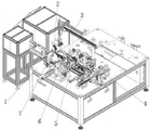
As shown in fig. 1, the automatic assembling device for efficient pressing of a pipe shaft assembly provided by the utility model is used for assembling the pipe shaft assembly formed by an automobile pedal module mechanism, the pipe shaft assembly comprises a pedal seat, a mounting hole for a pipe shaft to penetrate into is formed in the pedal seat, the pipe shaft adopts a T-shaped structure, one end of the pipe shaft penetrates into the side face of the pedal seat, the end part of the pipe shaft is fixed through a fixing ring, and the pedal is sleeved on the outer ring of the pipe shaft and is movably connected with the pipe shaft.
The assembling device comprises a workbench 1, a tubular shaft feeding device 2, a tubular shaft taking and transferring mechanism 3, a tubular shaft assembling mechanism 4, a pedal placing tool 5, a fixing ring pressing-in mechanism 6 and a fixing ring taking and transferring mechanism 7 are sequentially arranged on the workbench 1, the fixing ring taking and transferring mechanism 7 and the tubular shaft taking and transferring mechanism 3 are arranged side by side, and the tubular shaft taking and transferring mechanism 3 clamps a tubular shaft on the tubular shaft feeding device 2 and places the tubular shaft into the tubular shaft assembling mechanism 4 for press-fitting of the tubular shaft and the pedal; the pedal placing tool 5 is arranged on one side perpendicular to the press-fitting direction of the tubular shaft assembling mechanism 4, the pedal seat is fixed on the pedal placing tool 5, and the pedal placing tool 5 is connected with the workbench in a sliding mode along the pedal feeding direction; the fixing ring press-in mechanism 6 is arranged in parallel with the tubular shaft assembling mechanism 4, and after the tubular shaft is assembled, the fixing ring is pressed into the end part of the tubular shaft to fix the tubular shaft and the pedal seat.
According to the utility model, the devices or structures are driven by matching the cylinders and the sliding rails, so that the assembly precision of the tubular shaft assemblies can be ensured, and the qualification rate and the production efficiency are improved.
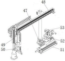
As shown in fig. 2, in a specific embodiment, the pipe shaft taking and transferring mechanism of the present invention includes a support frame 47 fixed on the workbench 1, a rodless cylinder 48 is horizontally fixed on the support frame 47, limit stops are arranged at two ends of the rodless cylinder 48 of the support frame 47, the limit stops are fixed on the support frame through screws, a sixth sliding table cylinder 49 is fixed at a driving end of the rodless cylinder 48, the sixth sliding table cylinder 49 is vertically arranged, and a pneumatic clamp 50 for clamping a pipe shaft is arranged at the driving end of the sixth sliding table cylinder 49; a seventh sliding table cylinder 51 parallel to the rodless cylinder 48 is arranged on one side of the supporting frame 47, an eighth sliding table cylinder 52 perpendicular to the sliding direction of the seventh sliding table cylinder is arranged on the driving end of the seventh sliding table cylinder 51, a swing air claw 53 is installed on the driving end of the eighth sliding table cylinder 52, the swing air claw 53 receives a pipe shaft on the pneumatic clamp 50, and the pipe shaft is placed on the pipe shaft assembling mechanism 4 by rotating 90 degrees.
A sixth sliding table cylinder 49 where a pneumatic clamp 50 is located reciprocates on a linear sliding rail along with a rodless cylinder 48, the sixth sliding table cylinder 49 slides downwards at a feeding port of the tubular shaft feeding equipment 2, the pneumatic clamp 50 clamps a tubular shaft, the sixth sliding table cylinder 49 resets, the rodless cylinder 48 drives the pneumatic clamp 50 to convey to the position of a swing air claw 53, the pneumatic clamp 50 moves downwards of the sixth sliding table cylinder 49 to open a part, the swing air claw 53 clamps the tubular shaft, the sixth sliding table cylinder 49 moves to the tubular shaft assembling mechanism 4 under the driving of an eighth sliding table cylinder 52, the sixth sliding table cylinder 49 resets at the same time, and the rodless cylinder 48 withdraws the part.
As shown in fig. 3 and 4, in a specific embodiment, the tube shaft assembling mechanism 4 of the present invention includes a tube shaft guide assembly for assisting the penetration of the tube shaft, a tube shaft press-fitting assembly for penetrating the tube shaft into the pedal seat and the pedal, and a pedal mounting and positioning assembly for press-fitting and positioning the pedal before the tube shaft is pressed, the tube shaft guide assembly includes two first supporting plates 8 oppositely disposed on the table 1, a first mounting plate 9 is disposed above the first supporting plate 8, the first mounting plate 9 is slidably coupled to an upper end of the first supporting plate 8 in the tube shaft assembling direction, a first cylinder 10 for driving the first mounting plate 9 to slide is disposed at one side of the first supporting plate 8, a guide positioning block 11 for corresponding to the tube shaft mounting hole on the pedal seat is disposed at one end of the first mounting plate 9 near the pedal seat, a guide rod 12 is penetrated in the guide positioning block 11, a first sliding table cylinder 13 for driving the guide rod 12 to move is arranged above the first mounting plate 9; a square bearing 72 is sleeved on the body of the guide rod 12, the square bearing 72 is fixed on the first mounting plate 9, the front end of the guide rod 12 penetrates through the square bearing 72 and then is located in the guide positioning block 11, and the tail end of the guide rod 12 is connected with the driving end of the first sliding table cylinder 13 through the second connecting block 61.
The first air cylinder 10 is pushed out, the connected first mounting plate 9 is pushed out forwards in a linkage mode, the guide positioning block 11 is in butt joint locking with the tubular shaft mounting hole of the pedal base, and the first sliding table air cylinder 13 drives the guide rod 12 to extend in place to conduct guiding of tubular shaft mounting.
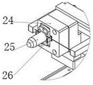
The tubular shaft press-in assembly comprises two second support plates 22 which are oppositely arranged, a third mounting plate 23 is connected above the two second support plates in a sliding mode, a mounting block 24 is fixed on the third mounting plate 23, a tubular shaft mounting pin 25 for tubular shaft mounting is arranged on one side, close to the guide rod 12, of the mounting block 24, mistake-proofing guide sheets 26 are arranged on two sides of the tubular shaft mounting pin 25 of the mounting block 24, and the mounting direction of a tubular shaft is confirmed through the mistake-proofing guide sheets 26; a press-fitting air cylinder 27 for driving the third mounting plate 23 to slide on the second support plate 22 along the assembling direction is arranged below the third mounting plate 23, the press-fitting air cylinder 27 is fixed on the second support plate 22, and the driving end of the press-fitting air cylinder 27 is fixedly connected with the third mounting plate 23 through a first connecting block 28 to drive the third mounting plate 23 to slide; the pipe shaft is arranged on the pipe shaft mounting pin 25 in a penetrating mode through the cooperation of the seventh sliding table cylinder 51 and the eighth sliding table cylinder 52, the third mounting plate 23 is driven to move by the press-fitting cylinder 27, the pipe shaft is further pushed into the mounting hole in the pedal seat, the first sliding table cylinder 13 is reset, the pipe shaft penetrates along with the guide rod 12, and pipe shaft assembly is completed; a sensor 29 for detecting the pipe shaft is arranged on one side of the pipe shaft press-in component, the sensor 29 is fixed on the workbench 1 through a mounting support rod 30, the sensor 29 is electrically connected with the press-fitting air cylinder 27, and the pipe shaft is automatically pressed in according to the information detected by the sensor.
In order to ensure that the guide rod 12 generates resilience in the guiding process and influence the press-fitting quality, as shown in fig. 5, a limiting block 14 is arranged below the first mounting plate 9, a first limiting cylinder 15 is arranged below the limiting block 14, the first limiting cylinder 15 is vertically arranged, the driving end is upward, and after the first mounting plate 9 is moved in place, the first limiting cylinder 15 blocks the limiting block 14 to prevent resilience.
In order to ensure that the position and the angle of the pedal are kept consistent in the pipe shaft penetrating process and improve the production yield and quality, the pedal mounting and positioning assembly comprises a second sliding table cylinder 16 arranged in parallel with a first sliding table cylinder 13, a second mounting plate 17 is fixed at the driving end of the second sliding table cylinder 16, and a profiling guide 18 arranged in a profiling way with the cross section of the pedal is arranged at the end part of the second mounting plate 17; a third sliding table cylinder 19 is arranged in the direction perpendicular to the second sliding table cylinder 16, a fourth sliding table cylinder 20 is fixed at the driving end of the third sliding table cylinder 19, the fourth sliding table cylinder 20 is vertically arranged on the third sliding table cylinder 19, a profiling pressing block 21 with the end matched with the edge shape of the pedal is fixed at the driving end of the fourth sliding table cylinder 20, and after the pedal is placed in, the profiling pressing block 21 is matched with the profiling guide 18 to fix the angle and the position of the pedal.
As shown in fig. 6, in a specific embodiment, the pedal placement tool 5 of the present invention includes a bottom plate 62 slidably connected to a table in a direction perpendicular to a tube axis installation direction, a third rodless cylinder 63 provided on one side of the bottom plate 62 and parallel to the sliding direction, the bottom plate 62 connected to a driving end of the third rodless cylinder 63, a tool plate 64 provided on the bottom plate 62 for fixing a pedal seat, the tool plate 64 slidably connected to the bottom plate 62 in a direction parallel to an axis of the tube axis, spring plungers 65 provided at both ends of the tool plate 64 in the sliding direction, the spring plungers 65 fixed to the bottom plate 62 by a fixing support 66, a positioning block 67 configured in accordance with a shape of the pedal seat provided above the tool plate 64, and a locking cylinder 68 provided on one side of the tool plate for product compression fixing, a polyurethane press block 69 fixed to a driving end of the locking cylinder 68, and pressed by the locking cylinder 68 after the position of the pedal seat is adjusted to a proper position, a third sensor 70, electrically connected to the lock cylinder 68, may be provided for detecting whether a product is placed on the tooling plate for automatic positioning and securing.
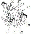
As shown in fig. 7 and 8, the fixing ring press-in mechanism of the present invention includes limiting assemblies symmetrically disposed at both sides of the pedal seat; set up the tight subassembly in hollow shaft top that is used for the tight restriction circumferential displacement in hollow shaft tip top on one of them spacing subassembly, set up the solid fixed ring subassembly of impressing that is used for solid fixed ring to impress on another spacing subassembly, spacing subassembly includes base 31, is equipped with the third backup pad 32 of two relative settings on base 31, all sets up a spacing cylinder 33 of second in every third backup pad, and the spacing cylinder 33 end fixing of second has the stopper 34 of passing third backup pad 32 face.
The tubular shaft jacking assembly comprises a jacking cylinder 35, a fourth mounting plate 36 and a push rod 37, the fourth mounting plate 36 is fixed at the driving end of the jacking cylinder 35 and is in sliding connection with the limiting assembly in the direction parallel to the tubular shaft, the push rod 37 is fixed at one side of the fourth mounting plate 36 close to the tubular shaft, and the end part of the tubular shaft is jacked in the process of press mounting of the fixing ring;
the fixing ring press-in component comprises a press-in support 38 and a servo cylinder 39, a fifth sliding table cylinder 40 for driving the press-in support to move integrally is arranged below the press-in support 38, a fifth mounting plate 41 is fixed at the driving end of the fifth sliding table cylinder 40, a pressure head fixing seat 42 is arranged at the front end of the press-in support 38 of the fifth mounting plate 41, the pressure head fixing seat 42 is connected with the fifth mounting plate 41 in a sliding mode along the direction perpendicular to the pipe shaft, a pressure head 43 for pressing in the fixing ring and a standby pressure head 44 for replacing when the pressure head is damaged are arranged on the pressure head fixing seat 42, the servo cylinder 39 is fixed on the press-in support 38, a push rod of the servo cylinder 39 passes through the press-in support 38 and then faces one side where the pipe shaft is located, the pressure head 43 and the standby pressure head 44 both pass through the pressure head fixing seat 42 and are matched with the push rod of the servo cylinder 39 through a pressing block 45, the push rod 43 slides on the pressure head fixing seat 42, and magnets for adsorbing the fixing ring are arranged at the end parts, which the pressure head 43 and the standby pressure head 44 are close to one side of the pipe shaft 46.
Whether fixed ring second sensor exists or not is arranged on one side of the pressure head fixing seat 42, the second sensor is electrically connected with the fifth sliding table cylinder 40, after the fixed ring is arranged on the pressure head 43, the fifth sliding table cylinder 40 drives the pressure head 43 to move in place, and the pressure head is pushed by the servo cylinder 39 to press the fixed ring.
As shown in fig. 9, the fixed ring taking and transferring mechanism 7 of the present invention includes a fixed bracket 54, a ninth sliding table cylinder 55 is vertically disposed on the fixed bracket 54, a connecting piece fixture 56 is fixed at a driving end of the ninth sliding table cylinder 55, and a blocking member is disposed on the connecting piece fixture 56 to prevent a product from falling off; set up second rodless cylinder 57 in the below of union piece frock 56, the fixed subassembly of transporting of drive end of second rodless cylinder 57, the subassembly of transporting includes linking bridge 58, sliding connection between linking bridge 58 lower part and the workstation 1, set up tenth slip table cylinder 59 above linking bridge 58, the slip direction of tenth slip table cylinder 59 drive end is perpendicular with the moving direction of second rodless cylinder 57, set up the clamping jaw cylinder 60 that is used for pressing from the clamp of union piece frock 56 and gets solid fixed ring at the drive end of tenth slip table cylinder 59, clamping jaw cylinder 60 presss from both sides and gets solid fixed ring after, drive through second rodless cylinder 57 and put solid fixed ring on solid fixed ring mechanism 6 of impressing and carry out the pressure equipment.
An adjusting bolt 71 used for adjusting the position of the fixing support can be arranged on the workbench 1, and the adjusting bolt 71 is rotated to adjust the fixing support 54 so as to adjust the relative position of the connecting piece tool and the clamping jaw air cylinder, so that the assembling requirements of products with different specifications can be met
When the automatic assembling device for efficient pressing of the pipe shaft assembly is used, the pipe shaft on the pipe shaft feeding equipment 2 is clamped by the pipe shaft taking and transferring mechanism 3 and is installed on the pipe shaft installing pin 25 of the pipe shaft assembling mechanism 4, and wrong installation of the pipe shaft is prevented through the mistake-proof guide sheet; meanwhile, a pedal placing tool 5 drives a pedal seat to slide on a workbench, the pedal seat is moved to a tubular shaft installation position, a pedal is installed from a profiling guide part 18, a fourth sliding table cylinder 20 drives a profiling pressing block 21 to press downwards, the position between the pedal and the pedal seat is fixed by matching with the profiling guide part 18, a first cylinder 10 drives a first installation plate 9 to move, a guide positioning block 11 corresponds to an installation hole on the pedal seat, a first sliding table cylinder 13 drives a guide rod 12 to penetrate in the tubular shaft, guiding in the process of penetrating the tubular shaft is carried out, a press-fitting cylinder 27 penetrates the tubular shaft, after the tubular shaft penetrates in, the tubular shaft adopts a T-shaped cross section structure, so that a fixing ring is required to be installed at one end with a smaller diameter of the tubular shaft for fixing, the pedal placing tool 5 is required to drive the pedal tool to move to a fixing ring press-fitting station, one end of the tubular shaft is tightly pressed by a tubular shaft pressing-fitting component, and the fixing ring pressing component at the other end presses in the fixing ring, in this process, the spacing cylinder 33 of second on the spacing subassembly carries on spacingly, prevents to take place to kick-back, and the pressure equipment quality can obtain guaranteeing.
The above description is only of the preferred embodiments of the present invention, and it should be noted that: it will be apparent to those skilled in the art that various modifications and adaptations can be made without departing from the principles of the utility model and these are intended to be within the scope of the utility model.
Claims (10)
1. An automatic assembling device for efficient pressing of a pipe shaft assembly comprises a pipe shaft penetrating through a pedal base, a pedal sleeved outside the pipe shaft and a fixing ring located at the end of the pipe shaft, wherein the fixing ring is used for fixing the pipe shaft and the pedal base; the pedal placing tool (5) is arranged on one side perpendicular to the press-fitting direction of the tubular shaft assembling mechanism (4), the pedal seat is fixed on the pedal placing tool (5), and the pedal placing tool (5) is connected with the workbench in a sliding mode along the pedal feeding direction; the fixing ring press-in mechanism (6) is arranged in parallel with the tubular shaft assembling mechanism (4), and after the tubular shaft is assembled, the fixing ring is pressed into the end part of the tubular shaft to fix the tubular shaft and the pedal seat.
2. The automatic assembling device for efficient pressing of the pipe shaft assemblies according to claim 1, wherein the pipe shaft assembling mechanism (4) comprises a pipe shaft guide assembly for assisting the penetration of the pipe shaft, a pipe shaft pressing assembly for penetrating the pipe shaft into the pedal seat and the pedal and a pedal mounting and positioning assembly for press-mounting and positioning the pedal before the pipe shaft is pressed, the pipe shaft guide assembly comprises two first supporting plates (8) oppositely arranged on the workbench (1), a first mounting plate (9) is arranged above the first supporting plates (8), the first mounting plate (9) is in sliding connection with the upper ends of the first supporting plates (8) along the pipe shaft assembling direction, a first air cylinder (10) for driving the first mounting plate (9) to slide is arranged on one side of the first supporting plates (8), a guide positioning block (11) corresponding to a pipe shaft mounting hole on the pedal seat is arranged at one end of the first mounting plate (9) close to the pedal seat, a guide rod (12) penetrates through the guide positioning block (11), and a first sliding table cylinder (13) for driving the guide rod (12) to move is arranged above the first mounting plate (9);
set up stopper (14) in the below of first mounting panel (9), set up first spacing cylinder (15) in the below of stopper (14), the vertical setting of first spacing cylinder (15), the drive end makes progress, removes the back that targets in place at first mounting panel (9), and first spacing cylinder (15) block stopper (14).
3. The automatic assembly device for efficient pressing of the pipe shaft assembly according to claim 2, wherein the pedal mounting and positioning assembly comprises a second sliding table cylinder (16) arranged in parallel with the first sliding table cylinder (13), a second mounting plate (17) is fixed to a driving end of the second sliding table cylinder (16), and a profiling guide (18) arranged in a profiling mode with respect to the cross section of the pedal is arranged at the end of the second mounting plate (17); set up third slip table cylinder (19) along the direction of perpendicular to second slip table cylinder (16), fix fourth slip table cylinder (20) at the drive end of third slip table cylinder (19), the vertical setting of fourth slip table cylinder (20) is on third slip table cylinder (19), be fixed with tip and footboard edge shape assorted copying press block (21) at the drive end of fourth slip table cylinder (20), after the footboard was put into, copying press block (21) cooperation copying guide (18) carry out the fixed of footboard angle and position.
4. The automatic assembling device for efficient pressing of the pipe shaft assemblies as claimed in claim 2, wherein the pipe shaft pressing-in assembly comprises two oppositely arranged second supporting plates (22), a third mounting plate (23) is slidably connected above the two second supporting plates, a mounting block (24) is fixed on the third mounting plate (23), a pipe shaft mounting pin (25) for pipe shaft mounting is arranged on one side of the mounting block (24) close to the guide rod (12), error-proof guide pieces (26) are arranged on the mounting block (24) on two sides of the pipe shaft mounting pin (25), and the mounting direction of the pipe shaft is confirmed through the error-proof guide pieces (26); a press-fitting air cylinder (27) used for driving the third mounting plate (23) to slide on the second supporting plate (22) along the assembling direction is arranged below the third mounting plate (23), the press-fitting air cylinder (27) is fixed on the second supporting plate (22), and the driving end of the press-fitting air cylinder (27) is fixedly connected with the third mounting plate (23) through a first connecting block (28) to drive the third mounting plate (23) to slide.
5. The automatic assembling device for efficient pressing of the pipe shaft assembly according to claim 2, wherein a sensor (29) for detecting the pipe shaft is arranged on one side of the pipe shaft pressing-in assembly, the sensor (29) is fixed on the workbench (1) through a mounting support rod (30), and the sensor (29) is electrically connected with the pressing cylinder (27).
6. The automatic assembling device for efficient pressing of the pipe shaft assembly according to claim 1, wherein the fixing ring pressing-in mechanism comprises limiting assemblies symmetrically arranged on two sides of the pedal seat; set up the tight subassembly in hollow shaft top that is used for the tight restriction circumferential displacement in hollow shaft tip top on one of them spacing subassembly, set up the solid fixed ring subassembly of impressing that is used for solid fixed ring to impress on another spacing subassembly, spacing subassembly includes base (31), is equipped with two third backup pads (32) that set up relatively on base (31), all sets up a spacing cylinder of second (33) in every third backup pad, and spacing cylinder of second (33) end fixing has stopper (34) of passing third backup pad (32) face.
7. The automatic assembling device for efficient pressing of the pipe shaft assemblies according to claim 6, wherein the pipe shaft pressing assembly comprises a pressing cylinder (35), a fourth mounting plate (36) and a push rod (37), the fourth mounting plate (36) is fixed at a driving end of the pressing cylinder (35) and is in sliding connection with the limiting assembly along a direction parallel to the pipe shafts, the push rod (37) is fixed at one side of the fourth mounting plate (36) close to the pipe shafts, and the end portions of the pipe shafts are pressed tightly in the process of pressing and mounting the fixing rings;
the fixing ring press-in component comprises a press-in support (38) and a servo cylinder (39), a fifth sliding table cylinder (40) for driving the press-in support to move integrally is arranged below the press-in support (38), a fifth mounting plate (41) is fixed at the driving end of the fifth sliding table cylinder (40), a pressure head fixing seat (42) is arranged at the front end of the press-in support (38) of the fifth mounting plate (41), the pressure head fixing seat (42) is in sliding connection with the fifth mounting plate (41) along the direction perpendicular to the pipe shaft, a pressure head (43) for press-in of the fixing ring and a standby pressure head (44) for replacement when the pressure head is damaged are arranged on the pressure head fixing seat (42), the servo cylinder (39) is fixed on the press-in support (38), a push rod of the servo cylinder (39) passes through the press-in support (38) and then just faces to the side where the pipe shaft is located, the pressure head (43) and the standby pressure head (44) both pass through the pressure head fixing seat (42) and are matched with the push rod of the servo cylinder (39) through a pressing block (45), the push rod pushes the pressure head (43) to slide on the pressure head fixing seat (42), and magnets (46) used for adsorbing the fixing rings are mounted at the end parts of the pressure head (43) and the standby pressure head (44) close to one side of the tubular shaft.
8. The automatic assembly device for efficient pressing of the pipe shaft assembly according to claim 1, wherein the pedal placement tool (5) comprises a bottom plate (62) which is in sliding connection with the workbench along a direction perpendicular to the installation direction of the pipe shaft, a third rodless cylinder (63) parallel to the sliding direction is arranged on one side of the bottom plate (62), the bottom plate (62) is connected with a driving end of the third rodless cylinder (63), a tool plate (64) used for fixing the pedal seat is arranged on the bottom plate (62), the tool plate (64) is in sliding connection with the bottom plate (62) along a direction parallel to the axis of the pipe shaft, spring plungers (65) are arranged at two ends of the sliding direction of the tool plate (64), the spring plungers (65) are fixed on the bottom plate (62) through fixing supports (66), a positioning block (67) designed according to the shape of the pedal seat and a locking cylinder (68) located on one side of the tool plate and used for compressing and fixing a product are arranged above the tool plate (64), a polyurethane pressing block (69) is fixed at the driving end of the locking cylinder (68), and is pressed by the locking cylinder (68) after the position of the pedal seat is adjusted to the right position; a third sensor (70) electrically connected to the lock cylinder (68) is provided on the tooling plate (64), and whether or not a product is placed on the tooling plate is detected by the third sensor (70).
9. The automatic assembling device for efficient pressing of the pipe shaft assemblies according to claim 1, wherein the pipe shaft taking and transferring mechanism comprises a support frame (47) fixed on the workbench (1), a rodless cylinder (48) is horizontally fixed on the support frame (47), a sixth sliding table cylinder (49) is fixed at the driving end of the rodless cylinder (48), the sixth sliding table cylinder (49) is vertically arranged, and a pneumatic clamp (50) for clamping the pipe shafts is arranged at the driving end of the sixth sliding table cylinder (49); a seventh sliding table cylinder (51) parallel to the rodless cylinder (48) is arranged on one side of the supporting frame (47), an eighth sliding table cylinder (52) perpendicular to the sliding direction of the seventh sliding table cylinder is arranged on the driving end of the seventh sliding table cylinder (51), a swing air claw (53) is mounted at the driving end of the eighth sliding table cylinder (52), the swing air claw (53) receives a pipe shaft on the pneumatic clamp (50), and the pipe shaft is placed on the pipe shaft assembling mechanism (4) by rotating 90 degrees.
10. The automatic assembling device for efficient pressing of the pipe shaft assembly according to claim 1, wherein the fixed ring taking and transferring mechanism (7) comprises a fixed support (54), a ninth sliding table air cylinder (55) is vertically arranged on the fixed support (54), and a connecting piece tool (56) is fixed at the driving end of the ninth sliding table air cylinder (55); set up second rodless cylinder (57) in the below of union piece frock (56), the fixed transportation subassembly of drive end of second rodless cylinder (57), the transportation subassembly includes linking bridge (58), sliding connection between linking bridge (58) lower part and workstation (1), set up tenth slip table cylinder (59) above linking bridge (58), the slip direction of tenth slip table cylinder (59) drive end is perpendicular with the moving direction of second rodless cylinder (57), set up clamping jaw cylinder (60) that are used for pressing from union piece frock (56) clamp solid fixed ring at the drive end of tenth slip table cylinder (59), clamping jaw cylinder (60) press from the solid fixed ring of clamp, after clamping jaw cylinder (60) clamp solid fixed ring, drive through second rodless cylinder (57) and put solid fixed ring and press in solid fixed ring mechanism (6) and carry out the pressure equipment.
Priority Applications (1)
| Application Number | Priority Date | Filing Date | Title |
|---|---|---|---|
| CN202122894816.1U CN216730477U (en) | 2021-11-24 | 2021-11-24 | Automatic assembly quality of high-efficient pressfitting of tube spindle subassembly |
Applications Claiming Priority (1)
| Application Number | Priority Date | Filing Date | Title |
|---|---|---|---|
| CN202122894816.1U CN216730477U (en) | 2021-11-24 | 2021-11-24 | Automatic assembly quality of high-efficient pressfitting of tube spindle subassembly |
Publications (1)
| Publication Number | Publication Date |
|---|---|
| CN216730477U true CN216730477U (en) | 2022-06-14 |
Family
ID=81929358
Family Applications (1)
| Application Number | Title | Priority Date | Filing Date |
|---|---|---|---|
| CN202122894816.1U Active CN216730477U (en) | 2021-11-24 | 2021-11-24 | Automatic assembly quality of high-efficient pressfitting of tube spindle subassembly |
Country Status (1)
| Country | Link |
|---|---|
| CN (1) | CN216730477U (en) |
-
2021
- 2021-11-24 CN CN202122894816.1U patent/CN216730477U/en active Active
Similar Documents
| Publication | Publication Date | Title |
|---|---|---|
| CN107971676B (en) | A kind of weld clamp method of automotive suspension control arm | |
| CN107962333B (en) | A kind of welding fixture of automotive suspension control arm | |
| CN108907462B (en) | Flexible tool fixture for laser welding of car lamp and welding method | |
| CN113118738A (en) | High-stability bearing press-riveting integrated machine | |
| CN216730477U (en) | Automatic assembly quality of high-efficient pressfitting of tube spindle subassembly | |
| CN117182520B (en) | Automatic press-fitting equipment and method for upper tubular column bearing of automobile steering system | |
| CN107900595B (en) | Welding positioning fixture for engine support sleeve | |
| CN214291596U (en) | Positioning tool for welding axle body | |
| CN103586808B (en) | Seat cushion positioning mechanism and control method thereof | |
| CN116604259B (en) | Clamp system and automatic welding workstation | |
| CN208929556U (en) | A kind of back-plate group is to tooling | |
| CN212705162U (en) | Welding tool for automobile backrest framework | |
| CN110480487A (en) | A kind of compound polishing board of multi-work piece | |
| CN107813074A (en) | A kind of automatic welding machine | |
| CN112975342A (en) | Exhaust gas recirculation valve assembly lining press mounting device | |
| CN212705161U (en) | Welding tool for automobile cushion framework | |
| CN218193101U (en) | Sheet metal spot welding clamp with detection function | |
| CN219005171U (en) | Conductive column assembling device | |
| CN112571308A (en) | Clamp for automobile parts | |
| CN220462908U (en) | Device for assembling and detecting retainer and upper cover of coil | |
| CN114769496B (en) | Production line clamp system and operation method thereof | |
| CN219787316U (en) | Screw locking device and screw locking system | |
| CN114406568B (en) | Auxiliary welding jig for server chassis and clamping method thereof | |
| CN210499323U (en) | Tight-lock coupler boring knuckle cavity tool | |
| CN221110559U (en) | Pipe fitting jig and pipe fitting elastic sheet assembling machine |
Legal Events
| Date | Code | Title | Description |
|---|---|---|---|
| GR01 | Patent grant | ||
| GR01 | Patent grant |