CN216708882U - Conveniently to furniture processing of material quick positioning and use engraver - Google Patents
Conveniently to furniture processing of material quick positioning and use engraver Download PDFInfo
- Publication number
- CN216708882U CN216708882U CN202122575349.6U CN202122575349U CN216708882U CN 216708882 U CN216708882 U CN 216708882U CN 202122575349 U CN202122575349 U CN 202122575349U CN 216708882 U CN216708882 U CN 216708882U
- Authority
- CN
- China
- Prior art keywords
- plate
- fixed mounting
- sides
- box
- processing
- Prior art date
- Legal status (The legal status is an assumption and is not a legal conclusion. Google has not performed a legal analysis and makes no representation as to the accuracy of the status listed.)
- Expired - Fee Related
Links
- 239000000463 material Substances 0.000 title claims abstract description 29
- 230000001681 protective effect Effects 0.000 claims description 4
- 238000000034 method Methods 0.000 abstract description 8
- 238000006073 displacement reaction Methods 0.000 description 4
- 230000004075 alteration Effects 0.000 description 1
- 230000009286 beneficial effect Effects 0.000 description 1
- 238000005520 cutting process Methods 0.000 description 1
- 238000005553 drilling Methods 0.000 description 1
- 238000004049 embossing Methods 0.000 description 1
- 238000002474 experimental method Methods 0.000 description 1
- 239000010977 jade Substances 0.000 description 1
- 238000010147 laser engraving Methods 0.000 description 1
- 238000004519 manufacturing process Methods 0.000 description 1
- 239000002184 metal Substances 0.000 description 1
- 238000003801 milling Methods 0.000 description 1
- 238000012986 modification Methods 0.000 description 1
- 230000004048 modification Effects 0.000 description 1
- 238000006467 substitution reaction Methods 0.000 description 1
- 238000003466 welding Methods 0.000 description 1
Images


Landscapes
- Milling, Drilling, And Turning Of Wood (AREA)
Abstract
The utility model discloses a carving machine for furniture processing, which is convenient for quickly positioning materials and comprises a box body, wherein a workbench is fixedly arranged at the top of the box body, mounting plates are fixedly arranged on two sides of the inner wall of the workbench, fixing plates are fixedly arranged on the front side and the rear side of the inner side of each mounting plate, and telescopic rods are fixedly arranged on the inner sides of the fixing plates. According to the utility model, the threaded rod is driven to rotate by the rotating device, so that the threaded block can effectively drive the clamping plate to move forwards and backwards and limit materials on the surface of the placing plate forwards and backwards, the telescopic rod can effectively limit the materials on the surface of the placing plate leftwards and rightwards through operation, the rotating device can effectively limit the threaded block in the process of driving the threaded rod to rotate through the limiting groove and the limiting block, the stability of the device in the operation process is improved, and the problem that the common engraving machine for furniture processing in the market is inconvenient to position the materials is solved.
Description
Technical Field
The utility model relates to the technical field of engraving machines, in particular to an engraving machine for furniture processing, which is convenient for quickly positioning materials.
Background
The engraving is a drilling and milling combined processing in principle, a plurality of data input modes of an engraving machine are redundant as required, a computer engraving machine has two types of laser engraving and mechanical engraving, the two types have high power and low power, the application range of the engraving machine is very wide, so that the most suitable application range of various engraving machines is needed to be known, the low power is only suitable for manufacturing bicolor plates, building models, small-sized labels, three-dimensional artware and the like, the power required for engraving jade, metal and the like is more than 1500W, the high-power engraving machine can be used as a small-power engraving machine and is most suitable for large-scale cutting, embossing and engraving, the common engraving machine for furniture processing in the market generally has the phenomenon of inconvenient material positioning, so that the material is easy to deviate in the material processing process of the device, and the processing progress of the material is seriously influenced, bringing inconvenience to the user.
SUMMERY OF THE UTILITY MODEL
The utility model aims to provide a carving machine for furniture processing, which is convenient for quickly positioning materials, has the advantage of convenient positioning and solves the problem that common carving machines for furniture processing in the market are generally inconvenient for positioning materials.
In order to achieve the purpose, the utility model provides the following technical scheme: the engraving machine for processing the furniture and convenient for quickly positioning the material comprises a box body, wherein a workbench is fixedly mounted at the top of the box body, mounting plates are fixedly mounted on two sides of the inner wall of the workbench, fixed plates are fixedly mounted on the front side and the rear side of the inner side of the mounting plates, telescopic rods are fixedly mounted on the inner sides of the fixed plates, a vertical plate is fixedly mounted in the middle of an inner cavity of the box body, rotating devices are fixedly mounted on the front side and the rear side of the vertical plate and on the front side and the rear side of the inner cavity of the box body, a threaded rod is fixedly connected to the inner side of each rotating device, a threaded block is in threaded connection with the surface of the threaded rod, a placing plate is fixedly mounted at the top of the box body, an outlet is formed in the top of the inner cavity of the box body and extends to the surface of the placing plate, clamping plates are fixedly connected to the tops of the threaded blocks and extend to the tops of the placing plates, bottom plates are fixedly mounted on the front side and the rear sides of the inner cavity of the box body and are positioned outside the vertical plate, the top of bottom plate has seted up the spacing groove, the inner chamber movable mounting of spacing groove has the stopper, the top fixedly connected with gag lever post of stopper, gag lever post and thread piece fixed connection.
Preferably, both sides of the box body are fixedly provided with side plates, the top of each side plate is provided with a sliding groove, and the inner cavity of each sliding groove is movably provided with a moving block.
Preferably, the top of the moving block is fixedly provided with a telescopic column, and the top of the telescopic column is fixedly connected with a top plate.
Preferably, the inner side of the top plate is fixedly provided with a sliding rail, and the inner cavity of the sliding rail is movably provided with a sliding block.
Preferably, the front surface of the sliding block is fixedly provided with a processing device, and two sides of the front surface of the box body are movably provided with a protective door.
Preferably, the two sides of the side plate are fixedly provided with supporting columns, and the bottom of each supporting column is fixedly provided with a bearing plate.
Compared with the prior art, the utility model has the following beneficial effects:
1. according to the utility model, the threaded rod is driven to rotate by the rotating device, so that the threaded block can effectively drive the clamping plate to move forwards and backwards and limit materials on the surface of the placing plate forwards and backwards, the telescopic rod can effectively limit the materials on the surface of the placing plate leftwards and rightwards through operation, the rotating device can effectively limit the threaded block in the process of driving the threaded rod to rotate through the limiting groove and the limiting block, the stability of the device in the operation process is improved, and the problem that the common engraving machine for furniture processing in the market is inconvenient to position the materials is solved.
2. The utility model can effectively drive the processing device to displace forwards and backwards through the arrangement of the sliding chute and the moving block, and can effectively drive the processing device to displace leftwards and rightwards through the arrangement of the sliding rail and the sliding block.
Drawings
FIG. 1 is a schematic structural view of the present invention;
FIG. 2 is a top view of the table structure of the present invention;
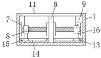
FIG. 3 is a side sectional view of the case structure of the present invention.
In the figure: 1. a box body; 2. a work table; 3. mounting a plate; 4. a fixing plate; 5. a telescopic rod; 6. a vertical plate; 7. a rotating device; 8. a threaded rod; 9. a thread block; 10. placing the plate; 11. an outlet; 12. a splint; 13. a base plate; 14. a limiting groove; 15. a limiting block; 16. a limiting rod; 17. a side plate; 18. a chute; 19. a telescopic column; 20. a top plate; 21. a slide rail; 22. a slider; 23. a processing device; 24. a protective door; 25. a support pillar; 26. a bearing plate; 27. moving the mass.
Detailed Description
The technical solutions in the embodiments of the present invention will be clearly and completely described below with reference to the drawings in the embodiments of the present invention, and it is obvious that the described embodiments are only a part of the embodiments of the present invention, and not all of the embodiments. All other embodiments, which can be obtained by a person skilled in the art without making any creative effort based on the embodiments in the present invention, belong to the protection scope of the present invention.
In the description herein, it is to be understood that the terms "center," "upper," "lower," "front," "rear," "left," "right," "vertical," "horizontal," "top," "bottom," "inner," "outer," and the like are used in the orientations and positional relationships indicated in the drawings to facilitate the description of the patent and to simplify the description, but do not indicate or imply that the referenced device or element must have a particular orientation, be constructed and operated in a particular orientation, and thus are not to be considered limiting of the patent. In the description of the present application, it should be noted that unless otherwise explicitly stated or limited, the terms "mounted," "connected," and "disposed" are to be construed broadly and can, for example, be fixedly connected, disposed, detachably connected, disposed, or integrally connected and disposed. The specific meaning of the above terms in this patent may be understood by those of ordinary skill in the art as appropriate.
Referring to fig. 1-3, an engraving machine for processing furniture, which facilitates quick positioning of materials, comprises a box body 1, side plates 17 are fixedly mounted on both sides of the box body 1, support columns 25 are fixedly mounted on both sides of the side plates 17, a bearing plate 26 is fixedly mounted at the bottoms of the support columns 25, a sliding chute 18 is formed in the top of the side plates 17, a processing device 23 can be effectively driven to move back and forth through the arrangement of the sliding chute 18 and a moving block 27, a moving block 27 is movably mounted in an inner cavity of the sliding chute 18, a telescopic column 19 is fixedly mounted at the top of the moving block 27, a top plate 20 is fixedly connected to the top of the telescopic column 19, a sliding rail 21 is fixedly mounted on the inner side of the top plate 20, the processing device 23 can be effectively driven to move left and right through the arrangement of the sliding rail 21 and the sliding block 22, a sliding block 22 is movably mounted in the inner cavity of the sliding rail 21, the processing device 23 is fixedly mounted on the front surface of the sliding block 22, protective doors 24 are movably mounted on two front sides of a box body 1, a workbench 2 is fixedly mounted on the top of the box body 1, mounting plates 3 are fixedly mounted on two sides of the inner wall of the workbench 2, fixing plates 4 are fixedly mounted on the front side and the rear side of the inner side of each mounting plate 3, telescopic rods 5 are fixedly mounted on the inner sides of the fixing plates 4, a vertical plate 6 is fixedly mounted in the middle of the inner cavity of the box body 1, rotating devices 7 are fixedly mounted on the front side and the rear side of each vertical plate 6 and the front side and the rear side of the inner cavity of the box body 1, a threaded rod 8 is fixedly connected to the inner side of each rotating device 7, a threaded block 9 is in threaded connection with the surface of each threaded rod 8, a placing plate 10 is fixedly mounted on the top of the box body 1, an outlet 11 is formed in the top of the inner cavity of the box body 1 and extends to the surface of the placing plate 10, clamping plates 12 are fixedly connected to the top of the threaded block 9 and extends to the top of the placing plate 10, bottom plates 13 are fixedly mounted on the front side and the rear side of the inner cavity of the box body 1 and on the outer sides of the vertical plate 6, spacing groove 14 has been seted up at the top of bottom plate 13, the inner chamber movable mounting of spacing groove 14 has stopper 15, stopper 15's top fixedly connected with gag lever post 16, gag lever post 16 and screw thread piece 9 fixed connection, it can make screw thread piece 9 drive splint 12 carry out displacement around and carry out spacing around to the material of placing board 10 surface effectively to drive threaded rod 8 through rotary device 7 and rotate, it can carry out spacing about to the material of placing board 10 surface effectively to operate through telescopic link 5, can make rotary device 7 drive threaded rod 8 carry out pivoted in-process spacing screw thread piece 9 through spacing groove 14 and stopper 15 effectively, the stability of device at the operation in-process has been promoted, the common engraver ubiquitous problem of for furniture processing to the material location inconvenience on the market has been solved simultaneously.
All the components in the utility model are universal standard components or components known by those skilled in the art, the structure and principle of the components can be known by technical manuals or conventional experimental methods, meanwhile, the standard components used in the application document can be purchased from the market, the components in the application document can be customized according to the description of the specification and the accompanying drawings, the specific connection mode of each component adopts the conventional means of mature bolts, rivets, welding and the like in the prior art, the machinery, the components and equipment adopt the conventional models in the prior art, the control mode is automatically controlled through a controller, the control circuit of the controller can be realized through simple programming of those skilled in the art, the components belong to the common knowledge in the art, and the application document is mainly used for protecting mechanical devices, so the detailed explanation of the control mode and circuit connection is omitted, no specific description will be made herein.
During the use, drive threaded rod 8 through rotary device 7 and rotate and can make the screw thread piece 9 drive splint 12 carry out displacement around and carry out the spacing around to the material of placing the board 10 surface, can carry out spacing about placing the material on board 10 surface through the operation of telescopic link 5, can make rotary device 7 drive threaded rod 8 and carry out pivoted in-process to screw thread piece 9 spacing through spacing groove 14 and stopper 15, can drive processingequipment 23 through spout 18 and movable block 27 and carry out displacement around, can drive processingequipment 23 through slide rail 21 and slider 22 and carry out the displacement of position about.
Although embodiments of the present invention have been shown and described, it will be appreciated by those skilled in the art that changes, modifications, substitutions and alterations can be made in these embodiments without departing from the principles and spirit of the utility model, the scope of which is defined in the appended claims and their equivalents.
Claims (6)
1. The utility model provides a convenient engraver for furniture processing to quick location of material, includes box (1), its characterized in that: the top fixed mounting of box (1) has workstation (2), the equal fixed mounting in both sides of workstation (2) inner wall has mounting panel (3), the equal fixed mounting in both sides has fixed plate (4) around mounting panel (3) inboard, the inboard fixed mounting of fixed plate (4) has telescopic link (5), the middle part fixed mounting of box (1) inner chamber has riser (6), equal fixed mounting has rotary device (7) around both sides and box (1) inner chamber around riser (6), the inboard fixedly connected with threaded rod (8) of rotary device (7), the surperficial threaded connection of threaded rod (8) has thread piece (9), the top fixed mounting of box (1) has places board (10), the top of box (1) inner chamber just extends to the surface of placing board (10) and has seted up export (11), the top of screw thread piece (9) just extends to the top fixedly connected with splint (12) of placing board (10), the equal fixed mounting in the outside that both sides just are located riser (6) around box (1) inner chamber bottom has bottom plate (13), spacing groove (14) have been seted up at the top of bottom plate (13), the inner chamber movable mounting of spacing groove (14) has stopper (15), the top fixedly connected with gag lever post (16) of stopper (15), gag lever post (16) and screw thread piece (9) fixed connection.
2. The engraving machine for processing furniture, convenient for quickly positioning materials according to claim 1, is characterized in that: both sides of the box body (1) are fixedly provided with side plates (17), the top of each side plate (17) is provided with a sliding groove (18), and the inner cavity of each sliding groove (18) is movably provided with a moving block (27).
3. The engraving machine for processing furniture, convenient for quickly positioning materials according to claim 2, is characterized in that: the top of the moving block (27) is fixedly provided with a telescopic column (19), and the top of the telescopic column (19) is fixedly connected with a top plate (20).
4. The engraving machine for furniture processing, which is convenient for quickly positioning materials, according to claim 3, is characterized in that: the inner side of the top plate (20) is fixedly provided with a sliding rail (21), and the inner cavity of the sliding rail (21) is movably provided with a sliding block (22).
5. The engraving machine for furniture processing, which is convenient for quickly positioning materials, according to claim 4, is characterized in that: the front surface of the sliding block (22) is fixedly provided with a processing device (23), and two sides of the front surface of the box body (1) are movably provided with protective doors (24).
6. The engraving machine for processing furniture, convenient for quickly positioning materials according to claim 2, is characterized in that: the equal fixed mounting in both sides of curb plate (17) has support column (25), the bottom fixed mounting of support column (25) has bearing plate (26).
Priority Applications (1)
| Application Number | Priority Date | Filing Date | Title |
|---|---|---|---|
| CN202122575349.6U CN216708882U (en) | 2021-10-26 | 2021-10-26 | Conveniently to furniture processing of material quick positioning and use engraver |
Applications Claiming Priority (1)
| Application Number | Priority Date | Filing Date | Title |
|---|---|---|---|
| CN202122575349.6U CN216708882U (en) | 2021-10-26 | 2021-10-26 | Conveniently to furniture processing of material quick positioning and use engraver |
Publications (1)
| Publication Number | Publication Date |
|---|---|
| CN216708882U true CN216708882U (en) | 2022-06-10 |
Family
ID=81877615
Family Applications (1)
| Application Number | Title | Priority Date | Filing Date |
|---|---|---|---|
| CN202122575349.6U Expired - Fee Related CN216708882U (en) | 2021-10-26 | 2021-10-26 | Conveniently to furniture processing of material quick positioning and use engraver |
Country Status (1)
| Country | Link |
|---|---|
| CN (1) | CN216708882U (en) |
-
2021
- 2021-10-26 CN CN202122575349.6U patent/CN216708882U/en not_active Expired - Fee Related
Similar Documents
| Publication | Publication Date | Title |
|---|---|---|
| CN208662625U (en) | Milling attachment | |
| CN216708882U (en) | Conveniently to furniture processing of material quick positioning and use engraver | |
| CN214417742U (en) | Numerical control multi-head angle face milling machine | |
| CN203019157U (en) | Horizontal composite processing center | |
| CN216126870U (en) | High-efficient machining center tilting mechanism | |
| CN213165391U (en) | Mechanical arm with adjustable use height | |
| CN114193170B (en) | Multifunctional drilling device for furniture design and drilling method thereof | |
| CN109365881A (en) | Move horizontally oblique-feeding Universal rotary milling drill tools | |
| CN216681102U (en) | Computer 3D engraver that uses in a flexible way | |
| CN213531709U (en) | Boring and milling machining device for machine manufacturing | |
| CN215970877U (en) | Numerical control engraving machine tool with limiting function | |
| CN216658297U (en) | Engraving machine with high working efficiency and good stability for furniture processing | |
| CN215239425U (en) | Positioning and clamping device for engraving machine machining | |
| CN221247726U (en) | Efficient drilling and milling processing equipment for hardware end face | |
| CN219881355U (en) | Processing equipment is used in water pump production | |
| CN219053919U (en) | Mechanical part machining clamping table | |
| CN220700785U (en) | Sculpture design workstation | |
| CN218283868U (en) | Workpiece fixing device for vertical machining center | |
| CN215393206U (en) | Laser engraving machine with dustproof effect and accurate positioning | |
| CN220838108U (en) | Gantry milling hole positioning device | |
| CN220902595U (en) | Tooling for machining inclined holes of metal shell | |
| CN216326911U (en) | Four-process double-station double-material-pushing cutting machine | |
| CN216781014U (en) | Vertical machining center with high product and machine body stability | |
| CN210588222U (en) | Workpiece guiding and positioning device of numerical control drilling machine | |
| CN217942541U (en) | Machining tool for producing micro excavator platform |
Legal Events
| Date | Code | Title | Description |
|---|---|---|---|
| GR01 | Patent grant | ||
| GR01 | Patent grant | ||
| CF01 | Termination of patent right due to non-payment of annual fee | ||
| CF01 | Termination of patent right due to non-payment of annual fee |
Granted publication date: 20220610 |