CN216632277U - Mechanism for quickly adjusting molding resilience value - Google Patents
Mechanism for quickly adjusting molding resilience value Download PDFInfo
- Publication number
- CN216632277U CN216632277U CN202122969664.7U CN202122969664U CN216632277U CN 216632277 U CN216632277 U CN 216632277U CN 202122969664 U CN202122969664 U CN 202122969664U CN 216632277 U CN216632277 U CN 216632277U
- Authority
- CN
- China
- Prior art keywords
- adjusting
- pull rod
- die base
- lower die
- upper die
- Prior art date
- Legal status (The legal status is an assumption and is not a legal conclusion. Google has not performed a legal analysis and makes no representation as to the accuracy of the status listed.)
- Active
Links
Images
Abstract
The utility model provides a quick adjustment shaping rebound volume mechanism, including last mould and lower mould, it includes the upper die base that sets gradually under to go up the mould, the upper padding plate, the punch holder, backstop board and take off the flitch, be equipped with two mounting grooves on the upper die base, be equipped with the regulation pull rod in the mounting groove, the nut of going up the regulation pull rod and the screw rod overcoat of going up the regulation pull rod between the mounting groove bottom have an adjusting spring, it passes the upper die base and connects the driving seat to go up the regulation pull rod, the driving seat passes the punch holder in proper order, the backstop board with take off the flitch and can stretch out and take off the flitch outside, two driving seats set up relatively. According to the utility model, the height of the driving seat is adjusted by arranging the gap adjusting block between the upper die base and the upper clamping plate, and the height of the driving seat directly influences the angle and the gap distance of the side adjusting slide block contacting the surface of the product, so that when the product is out of tolerance, the gap adjusting block can be correspondingly adjusted according to the value of the out-tolerance, the debugging process is convenient and quick, the debugging time is shortened, the die change amount is small, and the effect is stable.
Description
Technical Field
The utility model relates to the technical field of stamping dies, in particular to a structure for quickly adjusting molding resilience.
Background
In the prior art, materials processed by a stamping die have the phenomena of distortion, rebound and the like after forming due to the characteristics of the materials, and the deviation often exists between the materials and initial theoretical data. The subsequent adjustment of the angle and the clearance of the product is needed to reach a qualified state, and the adjustment mode and the period are not suitable for the high-quality development of the die.
Accordingly, the prior art is subject to improvements and enhancements.
SUMMERY OF THE UTILITY MODEL
Aiming at the defects in the prior art, the utility model aims to provide a mechanism for quickly adjusting the molding resilience, which has the advantages of convenient and quick debugging process, reduced die change, shortened debugging time and stable effect.
In order to achieve the purpose, the technical scheme adopted by the utility model is as follows:
a mechanism for quickly adjusting the forming resilience, which comprises an upper die and a lower die,
the upper die comprises an upper die base, an upper base plate, an upper clamping plate, a stop plate and a stripper plate which are sequentially arranged from top to bottom, wherein two mounting grooves are formed in the upper die base; an intermittent adjusting block for adjusting the stroke of the driving seat is also arranged between the upper die base and the upper clamping plate; the lower die comprises a lower die base and two lower die plates arranged on the lower die base in parallel, a shaping insert is arranged between the two lower die plates, side adjusting sliding blocks matched with the two driving bases are arranged between the shaping insert and the two lower die plates respectively, a groove is formed in the outer wall of the lower die plate, a lower adjusting pull rod is arranged in the groove, a lower adjusting spring is sleeved outside a screw rod of the lower adjusting pull rod between a screw cap of the lower adjusting pull rod and the bottom of the groove, and the lower adjusting pull rod penetrates through the lower die plates and is connected with the side adjusting sliding blocks.
Preferably, the intermittent type regulating block includes horizontal segment and vertical section, and the horizontal segment has the lower inclined plane with the upper inclined plane matched with in driving seat top, is equipped with the adjusting bolt who is used for adjusting the distance between vertical section and the upper plate on the vertical section.
Preferably, the maximum distance of adjustment of the adjusting bolt is 3 mm.
Preferably, the lower die base is provided with a lower limiting column matched with the upper limiting column on the upper die base.
Compared with the prior art, the utility model has the beneficial effects that:
due to the adoption of the structural design, the height of the driving seat is adjusted by the gap adjusting block arranged between the upper die base and the upper clamping plate, and the angle and the gap distance of the side-adjusting sliding block contacting the surface of a product are directly influenced by the height of the driving seat, so that the gap adjusting block can be correspondingly adjusted according to the out-of-tolerance value when the product is out-of-tolerance, the debugging flow is convenient and quick, the debugging time is shortened, the die change amount is small, and the effect is stable.
Drawings
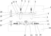
FIG. 1 is a schematic structural diagram of the present invention in the mold-open state.
The reference numbers in the figures are respectively: (1) the device comprises an upper die holder, (2) an upper backing plate, (3) an upper clamping plate, (4) a stop plate, (5) a stripper plate, (6) a mounting groove, (7) an upper adjusting screw, (8) an upper adjusting spring, (9) a clearance adjusting block, (10) a lower die holder, (11) a lower die plate, (12) a shaping insert, (13) a side adjusting slide block, (14) a groove, (15) a lower adjusting screw, (16) a lower adjusting spring, (17) a horizontal section, (18) a vertical section, (19) an adjusting bolt, (20) an upper limiting column, (21) a lower limiting column, and (22) a driving seat.
Detailed Description
The utility model is described in further detail below with reference to the accompanying drawings:
referring to fig. 1, the mechanism for rapidly adjusting the molding springback value of the present invention comprises an upper mold and a lower mold,
the upper die comprises an upper die base 1, an upper base plate 2, an upper clamping plate 3, a stop plate 4 and a stripper plate 5 which are sequentially arranged from top to bottom, two mounting grooves 6 are formed in the upper die base 1, an upper adjusting pull rod 7 is arranged in each mounting groove 6, an upper adjusting spring 8 is sleeved outside a screw rod of the upper adjusting pull rod between a nut of each upper adjusting pull rod 7 and the bottom of each mounting groove, each upper adjusting pull rod 7 penetrates through the upper die base 1 to be connected with a driving base 22, each driving base 22 sequentially penetrates through the upper clamping plate 3, the stop plate 4 and the stripper plate 5 and can extend out of the stripper plate 5, and the two driving bases 22 are oppositely arranged; an intermittent adjusting block 9 for adjusting the stroke of the driving seat is also arranged between the upper die holder 1 and the upper clamping plate 3; the lower die comprises a lower die base 10 and two lower die plates 11 arranged on the lower die base 10 in parallel, a shaping insert 12 is arranged between the two lower die plates 11, side adjusting sliding blocks 13 respectively matched with the two driving bases 22 are arranged between the shaping insert 12 and the two lower die plates 11, a groove 14 is formed in the outer wall of the lower die plate 11, a lower adjusting pull rod 15 is arranged in the groove, a lower adjusting spring 16 is sleeved outside a screw rod of the lower adjusting pull rod between a screw cap of the lower adjusting pull rod and the bottom of the groove, and the lower adjusting pull rod 15 penetrates through the lower die plates 11 and is connected with the side adjusting sliding blocks 13; the intermittent adjusting block 9 comprises a horizontal section 17 and a vertical section 18, the horizontal section 17 is provided with a lower inclined surface matched with the upper inclined surface at the top end of the driving seat, the vertical section 18 is provided with an adjusting bolt 19 for adjusting the distance between the vertical section and the upper clamping plate, and the maximum adjusting distance of the adjusting bolt is 3 mm.
When the adjustable gap adjusting block works, the distance between the vertical section and the upper clamping plate is adjusted through the adjusting bolt so that the horizontal section moves left and right, the horizontal section is provided with a lower inclined surface matched with the upper inclined surface at the top end of the driving seat, the horizontal section moves left or right so that the driving seat has different heights during processing, and the driving seat is matched with the side adjusting sliding block, so that the height of the driving seat directly influences the angle and the gap distance of the side adjusting sliding block contacting the surface of a product, and the gap adjusting block can be correspondingly adjusted according to the out-of-tolerance value when the product is out of tolerance.
The lower die holder 10 is provided with a lower limiting column 21 matched with the upper limiting column 20 on the upper die holder 1 and used for limiting the stroke of the upper die.
In conclusion, the utility model solves the defects in the prior art through the structural design and has the characteristics of reasonable structure, ingenious design, strong practicability and the like.
Claims (4)
1. A mechanism for quickly adjusting the forming resilience, which comprises an upper die and a lower die,
the method is characterized in that: the upper die comprises an upper die base, an upper base plate, an upper clamping plate, a stop plate and a stripper plate which are sequentially arranged from top to bottom, wherein two mounting grooves are formed in the upper die base; an intermittent adjusting block for adjusting the stroke of the driving seat is also arranged between the upper die base and the upper clamping plate; the lower die comprises a lower die base and two lower die plates arranged on the lower die base in parallel, a shaping insert is arranged between the two lower die plates, side adjusting sliding blocks matched with the two driving bases are arranged between the shaping insert and the two lower die plates respectively, a groove is formed in the outer wall of the lower die plate, a lower adjusting pull rod is arranged in the groove, a lower adjusting spring is sleeved outside a screw rod of the lower adjusting pull rod between a screw cap of the lower adjusting pull rod and the bottom of the groove, and the lower adjusting pull rod penetrates through the lower die plates and is connected with the side adjusting sliding blocks.
2. The mechanism for rapidly adjusting the forming springback value according to claim 1, wherein: the intermittent type regulating block includes horizontal segment and vertical section, and the horizontal segment has the lower inclined plane with the upper inclined plane matched with on drive seat top, is equipped with the adjusting bolt who is used for adjusting the distance between vertical section and the punch holder on the vertical section.
3. The mechanism for rapidly adjusting the forming springback value according to claim 1, wherein: the maximum distance adjusted by the adjusting bolt is 3 mm.
4. The mechanism for rapidly adjusting the forming springback value according to claim 1, wherein: the lower die base is provided with a lower limiting column matched with the upper limiting column on the upper die base.
Priority Applications (1)
| Application Number | Priority Date | Filing Date | Title |
|---|---|---|---|
| CN202122969664.7U CN216632277U (en) | 2021-11-30 | 2021-11-30 | Mechanism for quickly adjusting molding resilience value |
Applications Claiming Priority (1)
| Application Number | Priority Date | Filing Date | Title |
|---|---|---|---|
| CN202122969664.7U CN216632277U (en) | 2021-11-30 | 2021-11-30 | Mechanism for quickly adjusting molding resilience value |
Publications (1)
| Publication Number | Publication Date |
|---|---|
| CN216632277U true CN216632277U (en) | 2022-05-31 |
Family
ID=81737231
Family Applications (1)
| Application Number | Title | Priority Date | Filing Date |
|---|---|---|---|
| CN202122969664.7U Active CN216632277U (en) | 2021-11-30 | 2021-11-30 | Mechanism for quickly adjusting molding resilience value |
Country Status (1)
| Country | Link |
|---|---|
| CN (1) | CN216632277U (en) |
-
2021
- 2021-11-30 CN CN202122969664.7U patent/CN216632277U/en active Active
Similar Documents
| Publication | Publication Date | Title |
|---|---|---|
| CN208728475U (en) | It is a kind of can fast demoulding automobile die | |
| CN202045259U (en) | Adjustable precise U-shaped bending die | |
| CN202062006U (en) | Segment bolt forming die | |
| CN216027452U (en) | Die for punching metal plate | |
| CN201427372Y (en) | Obliquely-ejecting structure of die | |
| CN216632277U (en) | Mechanism for quickly adjusting molding resilience value | |
| CN108580693A (en) | Busbar Bending Mould | |
| CN208099065U (en) | A kind of hardware dies bent reshaping structure | |
| CN208450230U (en) | A kind of multidirectional single lead screw ex truding briquetting machine | |
| CN114433724B (en) | Forming die with adjustable gap for bending door shell end | |
| CN208341516U (en) | A kind of busbar Bending Mould | |
| CN208800663U (en) | A kind of stamping die of accurate positioning | |
| CN114101485A (en) | Adjustable bending die | |
| CN103111509A (en) | One-time punching device adjustable in three dimensions of vehicle window frame strip | |
| CN112405300A (en) | Polishing equipment suitable for injection mold | |
| CN206689300U (en) | A kind of high-precision bending and molding diel | |
| CN220162281U (en) | Hinge machine bush machining frock | |
| CN206215767U (en) | A kind of sequence frock of spring three | |
| CN220659097U (en) | Flexible extrusion forming device | |
| CN220112053U (en) | Sheet metal stamping die | |
| CN218873433U (en) | Punching die for pedal machining | |
| CN218196356U (en) | Novel die blank for groove-shaped die | |
| CN217550863U (en) | Mould with regulatory function | |
| CN204867090U (en) | Steel backing plastic mould of bending | |
| CN211329716U (en) | Shaping limiting device |
Legal Events
| Date | Code | Title | Description |
|---|---|---|---|
| GR01 | Patent grant | ||
| GR01 | Patent grant |