CN216583641U - Emergency rescue device for elevator without machine room - Google Patents
Emergency rescue device for elevator without machine room Download PDFInfo
- Publication number
- CN216583641U CN216583641U CN202122911972.4U CN202122911972U CN216583641U CN 216583641 U CN216583641 U CN 216583641U CN 202122911972 U CN202122911972 U CN 202122911972U CN 216583641 U CN216583641 U CN 216583641U
- Authority
- CN
- China
- Prior art keywords
- elevator
- chain
- machine room
- emergency rescue
- compensation chain
- Prior art date
- Legal status (The legal status is an assumption and is not a legal conclusion. Google has not performed a legal analysis and makes no representation as to the accuracy of the status listed.)
- Active
Links
Images

Landscapes
- Maintenance And Inspection Apparatuses For Elevators (AREA)
Abstract
The utility model discloses an emergency rescue device for a machine-room-less elevator, which comprises an elevator car frame and an elevator counterweight frame; the elevator compensation device is characterized by further comprising a compensation chain and a driving device used for selectively connecting and dragging the compensation chain, two ends of the compensation chain are respectively connected to the elevator car frame and the elevator counterweight frame, two ends of the compensation chain are vertically arranged under the action of gravity, and the driving device is arranged in a pit of the elevator without a machine room. Through setting up compensation chain and drive arrangement, when needs rescue, connect drive arrangement's effect end on the compensation chain to break the elevator and to the balanced state of heavy and elevator car, make elevator car remove to the flat bed, convenient rescue, rescue device simple structure, convenient to use.
Description
Technical Field
The utility model relates to the technical field of elevators, in particular to an emergency rescue device for a machine-room-less elevator.
Background
At present, because the elevator without a machine room occupies a small space, the elevator without the machine room is more and more widely used, and the product demand of the elevator without the machine room in the market is increased day by day; when the elevator without the machine room normally runs, if power is suddenly cut off, the elevator car can stop between two adjacent floors, so that passengers in the elevator are trapped; although the elevator can be moved to the flat layer openable door state by loosening the contracting brake, when the elevator car is close to the weight of the counterweight block, the elevator car and the counterweight block are in a balanced state, so that the elevator cannot move, and the rescue difficulty is increased.
Therefore, a new technical solution is needed to solve the above problems.
SUMMERY OF THE UTILITY MODEL
In view of the above, the present invention provides an emergency rescue device for a machine room-less elevator, which comprises a compensation chain and a driving device, wherein when rescue is required, an action end of the driving device is connected to the compensation chain to break a balance state between a counterweight and an elevator car of the elevator, so that the elevator car moves to a flat floor, rescue is facilitated, and the rescue device has a simple structure and is convenient to use.
In order to achieve the purpose, the utility model adopts the following technical scheme:
an emergency rescue device for a machine-room-less elevator comprises an elevator car frame and an elevator counterweight frame; the elevator is characterized by further comprising a compensation chain and a driving device used for being selectively connected with and dragging the compensation chain, wherein two ends of the compensation chain are respectively connected to the elevator car frame and the elevator counterweight frame, two ends of the compensation chain are vertically arranged due to the action of gravity, and the driving device is arranged in a pit of the elevator without a machine room.
As a preferred scheme, a first fixing piece is arranged at the bottom of the elevator car frame, a second fixing piece is arranged at the bottom of the elevator counterweight frame, and two ends of the compensation chain are respectively connected to the corresponding first fixing piece and the second fixing piece.
Preferably, the first fixing piece has two symmetrically arranged fixing pieces; in the two first fixing pieces, one of the two first fixing pieces is connected with a first chain ring at the elevator car frame end of the compensating chain, and the other one is connected with a second chain ring at the elevator car frame end of the compensating chain through a first safety chain.
Preferably, the second fixing member is connected to a first chain ring of an elevator counterweight frame end of the compensating chain, and a second chain ring of the elevator counterweight frame end of the compensating chain is connected with the elevator counterweight frame through a second safety chain.
Preferably, the first fixing member and the second fixing member each have a U-shaped hook, and both ends of the compensation chain are connected to the respective U-shaped hooks.
Preferably, the driving device is fixed on the bottom surface of a pit of the machine room-less elevator through a fixed seat.
Preferably, the driving device is a manual hoist or an electric hoist.
Preferably, the radius of the bottom fillet of the compensating chain is not less than 300 mm.
Preferably, the distance between the bottom end of the compensation chain and the bottom surface of the pit of the machine room-less elevator is more than 100 mm.
Preferably, the distance between the bottom end of the compensation chain and the bottom surface of the pit of the elevator without the machine room is 120 mm and 180 mm.
Compared with the prior art, the utility model has obvious advantages and beneficial effects, and specifically, the technical scheme includes that:
the rescue device is mainly characterized in that a compensation chain and a driving device are arranged, when rescue is needed, the action end of the driving device is connected to the compensation chain so as to break the balance state of the elevator counterweight and the elevator car, the elevator car is moved to a flat floor, rescue is facilitated, and the rescue device is simple in structure and convenient to use;
secondly, the safety of the rescue device is further ensured by the arrangement of the first safety chain and the second safety chain;
moreover, the driving device is fixed on the pit through the fixing seat, so that the use is convenient and the operation is simple.
To more clearly illustrate the structural features and effects of the present invention, the present invention will be described in detail below with reference to the accompanying drawings and specific embodiments.
Drawings
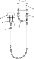
FIG. 1 is a schematic structural diagram (including a pit) of a preferred embodiment of the present invention;
FIG. 2 is a schematic structural diagram (without pit) of the preferred embodiment of the present invention.
The attached drawings indicate the following:
10. elevator car frame 11 and first fixing piece
20. Elevator counterweight housing 21 and second fixing member
30. Compensation chain 40 and drive device
50. Pit 60, fixing seat
70. A first safety chain 80 and a second safety chain.
Detailed Description
Referring to fig. 1 to 2, a specific structure of a preferred embodiment of the present invention is shown, which includes an elevator car frame 10, an elevator counterweight frame 20; the elevator is characterized by further comprising a compensation chain 30 and a driving device 40 used for selectively connecting and dragging the compensation chain 30, two ends of the compensation chain 30 are respectively connected to the elevator car frame 10 and the elevator counterweight frame 20, two ends of the compensation chain 30 are vertically arranged under the action of gravity, and the driving device 40 is arranged in a pit 50 of the elevator without a machine room. The elevator car frame 10 is located at the bottom of the elevator car, and the elevator counterweight frame 20 is located at the bottom of the elevator counterweight.
Specifically, a first fixing member 11 is disposed at the bottom of the elevator car frame 10, a second fixing member 21 is disposed at the bottom of the elevator counterweight frame 20, and two ends of the compensating chain 30 are respectively connected to the first fixing member 11 and the second fixing member 21; and the driving device 40 is fixed on the bottom surface of the pit 50 of the elevator without machine room through a fixed seat 60, and the driving device 40 is a hand-operated hoist or an electric hoist.
Further, the first fixing member 11 has two symmetrically arranged members; one of the two first fixing pieces 11 is connected with the first chain ring of the elevator car frame end of the compensating chain 30, and the other one is connected with the second chain ring of the elevator car frame end of the compensating chain 30 through a first safety chain 70; and the second fixing member 21 is connected to the first chain ring of the elevator counterweight frame end of the compensating chain 30, and the second chain ring of the elevator counterweight frame end of the compensating chain 30 is connected with the elevator counterweight frame through a second safety chain 80.
Preferably, the first fixing part 11 and the second fixing part 21 are provided with U-shaped hook portions, and both ends of the compensation chain 30 are connected to the corresponding U-shaped hook portions; and, the bottom fillet radius of the compensation chain 30 is not less than 300 mm;
in addition, the distance between the bottom end of the compensation chain 30 and the bottom surface of the elevator pit 50 without the machine room is more than 100mm, and the distance between the bottom end of the compensation chain 30 and the bottom surface of the elevator pit 50 without the machine room is preferably 120 mm and 180 mm.
Compared with the prior art, the utility model has obvious advantages and beneficial effects, and specifically, the technical scheme includes that:
detailed description the method of use of this example is as follows:
when the elevator works normally, the driving device 40 is not connected with the compensating chain 30, and the driving device 40 is placed at one corner of the pit;
in emergency rescue, more than two persons can operate as required in rescue operation, one person remotely loosens the brake of the tractor, the other rescue worker is matched with the pit 50 and is connected with the compensation chain 30 by the driving device 40, and then drags the compensation chain 30 to drive the lift car to move to a door opening area to rescue the persons.
The design of the utility model is characterized in that:
the rescue device is mainly characterized in that a compensation chain and a driving device are arranged, when rescue is needed, the action end of the driving device is connected to the compensation chain so as to break the balance state of the elevator counterweight and the elevator car, the elevator car is moved to a flat floor, rescue is facilitated, and the rescue device is simple in structure and convenient to use;
secondly, the safety of the rescue device is further ensured by the arrangement of the first safety chain and the second safety chain;
moreover, the driving device is fixed on the pit through the fixing seat, so that the driving device is convenient to use and simple to operate.
The above description is only a preferred embodiment of the present invention, and is not intended to limit the technical scope of the present invention, so that any minor modifications, equivalent changes and modifications made to the above embodiment according to the technical spirit of the present invention are within the technical scope of the present invention.
Claims (10)
1. An emergency rescue device for a machine-room-less elevator comprises an elevator car frame and an elevator counterweight frame; the method is characterized in that: the elevator is characterized by further comprising a compensation chain and a driving device used for being selectively connected with and dragging the compensation chain, wherein two ends of the compensation chain are respectively connected to the elevator car frame and the elevator counterweight frame, two ends of the compensation chain are vertically arranged due to the action of gravity, and the driving device is arranged in a pit of the elevator without a machine room.
2. The emergency rescue apparatus for an elevator without a machine room according to claim 1, characterized in that: the bottom of elevator sedan-chair frame is provided with first mounting, the bottom of elevator counterweight frame is provided with the second mounting, the both ends of compensation chain are connected respectively in corresponding first mounting and second mounting.
3. The emergency rescue apparatus for the elevator without the machine room according to claim 2, characterized in that: the first fixing piece is provided with two symmetrically arranged fixing pieces; in the two first fixing pieces, one of the two first fixing pieces is connected with a first chain ring at the elevator car frame end of the compensating chain, and the other one is connected with a second chain ring at the elevator car frame end of the compensating chain through a first safety chain.
4. The emergency rescue apparatus for the elevator without the machine room according to claim 2 or 3, characterized in that: the second fixing piece is connected to the first chain ring of the elevator counterweight frame end of the compensating chain, and the second chain ring of the elevator counterweight frame end of the compensating chain is connected with the elevator counterweight frame through a second safety chain.
5. The emergency rescue apparatus for the elevator without the machine room according to claim 2, characterized in that: the first fixing piece and the second fixing piece are provided with U-shaped hook portions, and two ends of the compensation chain are connected to the corresponding U-shaped hook portions.
6. The emergency rescue apparatus for the elevator without the machine room according to claim 1, characterized in that: the driving device is fixed on the bottom surface of a pit of the machine room free elevator through a fixed seat.
7. The emergency rescue apparatus for the elevator without the machine room according to claim 1 or 6, characterized in that: the driving device is a manual hoist or an electric hoist.
8. The emergency rescue apparatus for the elevator without the machine room according to claim 1, characterized in that: the radius of the bottom fillet of the compensation chain is not less than 300 mm.
9. The emergency rescue apparatus for a machine-roomless elevator according to claim 1 or 8, characterized in that: the distance between the bottom end of the compensation chain and the bottom surface of a pit of the machine-roomless elevator is more than 100 mm.
10. The emergency rescue apparatus for the elevator without the machine room according to claim 9, characterized in that: the distance between the bottom end of the compensation chain and the bottom surface of the pit of the machine room-less elevator is 120 mm and 180 mm.
Priority Applications (1)
| Application Number | Priority Date | Filing Date | Title |
|---|---|---|---|
| CN202122911972.4U CN216583641U (en) | 2021-11-25 | 2021-11-25 | Emergency rescue device for elevator without machine room |
Applications Claiming Priority (1)
| Application Number | Priority Date | Filing Date | Title |
|---|---|---|---|
| CN202122911972.4U CN216583641U (en) | 2021-11-25 | 2021-11-25 | Emergency rescue device for elevator without machine room |
Publications (1)
| Publication Number | Publication Date |
|---|---|
| CN216583641U true CN216583641U (en) | 2022-05-24 |
Family
ID=81650652
Family Applications (1)
| Application Number | Title | Priority Date | Filing Date |
|---|---|---|---|
| CN202122911972.4U Active CN216583641U (en) | 2021-11-25 | 2021-11-25 | Emergency rescue device for elevator without machine room |
Country Status (1)
| Country | Link |
|---|---|
| CN (1) | CN216583641U (en) |
-
2021
- 2021-11-25 CN CN202122911972.4U patent/CN216583641U/en active Active
Similar Documents
| Publication | Publication Date | Title |
|---|---|---|
| CN201201836Y (en) | Elevator car frame arrangement structure | |
| DE50011130D1 (en) | ROPE LIFT | |
| CN108328456B (en) | Guide rail for elevator | |
| CN102092614A (en) | Power failure rescue device of elevator without machine room | |
| CN201999600U (en) | Rescuing device for power cut of elevator without machine room | |
| CN216583641U (en) | Emergency rescue device for elevator without machine room | |
| JP2000086109A5 (en) | ||
| CN210339990U (en) | Hoistway type elevator self-rescuing and escaping device | |
| JP2001080837A (en) | Elevator device | |
| CN217627048U (en) | Elevator with mixed traction for hoistway | |
| CN211034791U (en) | Elevator emergency rescue device | |
| JP2011111283A (en) | Confinement rescue method of elevator | |
| CN205709375U (en) | A kind of self-balancing duplex elevator being applied in relatively adult's flow occasion | |
| CN214780113U (en) | Host top-hanging type elevator without machine room | |
| CN213011420U (en) | Emergency brake device of high-speed elevator | |
| CN212740295U (en) | Emergency anti-falling safety device for building construction elevator | |
| CN212198072U (en) | Twin elevator system | |
| CN213294354U (en) | Lifting mechanism for lifting box type elevator | |
| CN204434033U (en) | A kind of elevator | |
| CN208454212U (en) | A kind of compensation chain guiding device | |
| CN105936461A (en) | Self-balancing dual-elevator applied to occasions with high human traffic | |
| CN218754595U (en) | Low space host computer hoist device of no computer lab | |
| JP2001097648A (en) | Passenger rescue method of elevator | |
| CN210340019U (en) | Elevator traction mechanism | |
| CN109678027A (en) | A kind of anti-falling safe elevator |
Legal Events
| Date | Code | Title | Description |
|---|---|---|---|
| GR01 | Patent grant | ||
| GR01 | Patent grant |