CN216463756U - Cylindrical product mirror surface polishing machine - Google Patents
Cylindrical product mirror surface polishing machine Download PDFInfo
- Publication number
- CN216463756U CN216463756U CN202123017114.1U CN202123017114U CN216463756U CN 216463756 U CN216463756 U CN 216463756U CN 202123017114 U CN202123017114 U CN 202123017114U CN 216463756 U CN216463756 U CN 216463756U
- Authority
- CN
- China
- Prior art keywords
- cylindrical product
- belt
- driving mechanism
- polishing machine
- clamping
- Prior art date
- Legal status (The legal status is an assumption and is not a legal conclusion. Google has not performed a legal analysis and makes no representation as to the accuracy of the status listed.)
- Active
Links
Images


Landscapes
- Finish Polishing, Edge Sharpening, And Grinding By Specific Grinding Devices (AREA)
Abstract
The utility model relates to the technical field of polishing machines, and discloses a mirror polishing machine for cylindrical products, which comprises a machine table; the clamping device is arranged on the machine table, is used for clamping the cylindrical product and can drive the cylindrical product to rotate; the abrasive belt mechanism is arranged on the machine table and is configured to move along a first direction and a second direction, two groups are arranged, one group is used for roughly polishing the cylindrical product, the other group is used for finely polishing the cylindrical product, and the first direction and the second direction are perpendicular to each other. The cylindrical product is fixed on the clamping device, the cylindrical product can also rotate along with the cylindrical product under the fixation of the clamping device, the abrasive belt mechanism can move along the first direction and the second direction, so that the cylindrical product is polished, the abrasive belt mechanism is provided with two groups, one group is used for rough polishing, the other group is used for fine polishing, the rough polishing and the fine polishing are integrated on the same equipment and are simultaneously carried out, and the mirror polishing efficiency is improved.
Description
Technical Field
The utility model relates to a burnishing machine technical field especially relates to a cylindrical product mirror surface burnishing machine.
Background
The polishing machine is used for polishing the surface gloss and removing burrs of a workpiece in a full-automatic mode by utilizing automatic equipment, while the mirror surface polishing machine is required to polish the surface of the workpiece more finely, the requirement on the surface gloss is higher, in the prior art, the mirror surface polishing of a cylindrical product is usually required to be carried out through two polishing steps, the first step is coarse grinding polishing, the second step is fine grinding polishing, the two steps are completed in different equipment, and the polishing efficiency is low.
SUMMERY OF THE UTILITY MODEL
Based on it, an object of the utility model is to provide a cylindrical product mirror finish machine can effectual improvement polishing efficiency.
In order to achieve the purpose, the utility model adopts the following technical proposal:
the utility model provides a cylindrical product mirror finish machine, include:
a machine platform;
the clamping device is arranged on the machine table, is used for clamping the cylindrical product and can drive the cylindrical product to rotate;
the abrasive belt mechanism is arranged on the machine table and is configured to move along a first direction and a second direction, two groups are arranged, one group is used for roughly polishing the cylindrical product, the other group is used for finely polishing the cylindrical product, and the first direction and the second direction are perpendicular to each other.
Furthermore, the abrasive belt mechanism comprises a box body fixing plate, a first abrasive belt driving mechanism is arranged on the box body fixing plate, an abrasive belt driving wheel is arranged at the output end of the first abrasive belt driving mechanism, the box body fixing plate extends towards the direction of the clamping device and is rotatably provided with an abrasive belt idler wheel, and an abrasive belt is sleeved between the abrasive belt driving wheel and the abrasive belt idler wheel.
Furthermore, a position feeding cylinder is further arranged on the box body fixing plate, a idler wheel mounting frame is arranged at the output end of the position feeding cylinder, and the abrasive belt idler wheel is rotatably arranged on the idler wheel mounting frame.
Furthermore, a sand belt swing motor 36 is further arranged on the box fixing plate, an eccentric coupling is arranged at the output end of the sand belt swing motor 36 and connected with the position feeding cylinder, and the sand belt swing motor 36 rotates to enable the sand belt idler wheel to move in a reciprocating manner along the first direction.
Further, the eccentric coupling is connected with the feeding cylinder and comprises:
the eccentric coupling is connected with a first moving frame, the feeding cylinder is installed on a second moving frame, the first moving frame is connected with the second moving frame through a sliding rod, the first moving frame is arranged on one side of the box body fixing plate, the second moving frame is arranged on the other side of the box body fixing plate, and the sliding rod can penetrate through the box body fixing plate in a sliding mode.
Furthermore, a first slide rail is arranged on the machine table along the first direction, a module moving plate is arranged on the first slide rail in a sliding mode, a second slide rail is arranged on the module moving plate along the second direction, and the abrasive belt mechanism is arranged on the second slide rail in a sliding mode.
Furthermore, the machine table is further provided with a rack along a first direction, a second driving mechanism is arranged on the rack and can move on the rack along the first direction, and the second driving mechanism is further connected with a second driving mechanism base plate which is connected with the abrasive belt mechanism.
Further, the clamping device comprises a first clamping mechanism for fixing one end of the cylindrical product and a second clamping mechanism for fixing the other end of the cylindrical product;
the second clamping mechanism is configured to be movable in a first direction.
Further, the first clamping mechanism comprises a main shaft box body, and a three-jaw chuck is rotatably arranged on the main shaft box body;
the machine table is further provided with a third driving mechanism, and the output end of the third driving mechanism is connected with the three-jaw chuck to drive the three-jaw chuck to rotate.
Furthermore, a third slide rail is arranged on the machine table along the first direction, the second clamping mechanism comprises a pneumatic tailstock, and the pneumatic tailstock is arranged on the third slide rail in a sliding manner;
and the machine table is also provided with a fourth driving mechanism, and the output end of the fourth driving mechanism is connected with the pneumatic tailstock.
The utility model has the advantages that:
the utility model provides a cylindrical product mirror surface burnishing machine is fixed in clamping device with cylindrical product, and under clamping device's is fixed, cylindrical product also can rotate thereupon, and abrasive band mechanism can follow first direction and second direction and remove to polish cylindrical product, and abrasive band mechanism is provided with two sets ofly, and a set of thick throwing that carries on, a set of thin throwing that carries on, thick throwing and thin throwing all assemble on same equipment, and go on simultaneously, improved mirror surface polishing efficiency.
Drawings
In order to more clearly illustrate the technical solutions in the embodiments of the present invention, the drawings required to be used in the description of the embodiments of the present invention will be briefly described below, and it is obvious that the drawings in the following description are only some embodiments of the present invention, and for those skilled in the art, other drawings can be obtained according to the contents of the embodiments of the present invention and the drawings without creative efforts.
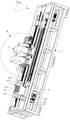
Fig. 1 is a schematic structural diagram of a mirror polishing machine for cylindrical products according to an embodiment of the present invention;
FIG. 2 is a top view of a mirror polishing machine for cylindrical products according to an embodiment of the present invention;
fig. 3 is a front view of a mirror polishing machine for cylindrical products according to an embodiment of the present invention;
fig. 4 is a left side view of a cylindrical product mirror polishing machine according to an embodiment of the present invention;
FIG. 5 is an enlarged schematic view of A of FIG. 1;
fig. 6 is a schematic structural diagram of an abrasive belt mechanism according to an embodiment of the present invention;
fig. 7 is a schematic view of another visual structure of a belt mechanism according to an embodiment of the present invention;
fig. 8 is an enlarged schematic view of the structure at B of fig. 3.
In the figure:
x, a first direction; y, a second direction;
1. a machine platform;
2. a clamping device; 21. a first clamping mechanism; 211. a main shaft box body; 212. a main shaft; 213. a three-jaw chuck; 214. a first clamping follower wheel; 215. a first clamping driving wheel; 216. a third drive mechanism; 217. a first clamping belt; 22. a second clamping mechanism; 221. a pneumatic tailstock; 222. a third slide rail; 223. a second clamping screw rod; 224. a deep groove ball bearing; 225. a second clamping follower wheel; 226. a fourth drive mechanism; 227. a second clamping driving wheel; 228. a second clamping belt; 229. an angular contact bearing;
3. an abrasive belt mechanism; 31. a box body fixing plate; 311. a box body side plate; 312. a box body bottom plate; 313. a box body vertical plate; 32. a first belt drive mechanism; 321. a belt drive motor; 322. a belt-driven reducer; 33. an abrasive belt idler wheel; 331. a position-feeding cylinder; 332. a idler wheel mounting bracket; 334. a second movable frame; 335. a slide bar; 34. a sand belt transmission wheel; 35. an abrasive belt; 36. a belt swinging motor; 37. an eccentric coupling; 371. a first movable frame; 38. a belt wheel; 39. a sand belt follow-up wheel;
4. a first slide rail;
5. a module moving plate; 51. a second slide rail; 52. a second slider; 53. a second threaded rod; 54. a second moving block;
6. a rack;
7. a second drive mechanism; 71. a second servo motor; 72. a second speed reducer; 73. a drag chain;
8. a second drive mechanism backing plate.
Detailed Description
In order to make the technical problems, technical solutions and technical effects achieved by the present invention more clear, the embodiments of the present invention will be described in further detail with reference to the accompanying drawings, and obviously, the described embodiments are only some embodiments, not all embodiments of the present invention. Based on the embodiments in the present invention, all other embodiments obtained by those skilled in the art without creative efforts belong to the protection scope of the present invention.
In the description of the present invention, unless expressly stated or limited otherwise, the terms "connected," "connected," and "fixed" are to be construed broadly, e.g., as meaning permanently connected, detachably connected, or integral to one another; can be mechanically or electrically connected; either directly or indirectly through intervening media, either internally or in any other relationship. The specific meaning of the above terms in the present invention can be understood in specific cases to those skilled in the art.
In the present disclosure, unless expressly stated or limited otherwise, the first feature "on" or "under" the second feature may comprise direct contact between the first and second features, or may comprise contact between the first and second features not directly. Also, the first feature being "on," "above" and "over" the second feature includes the first feature being directly on and obliquely above the second feature, or merely indicating that the first feature is at a higher level than the second feature. A first feature being "under," "below," and "beneath" a second feature includes the first feature being directly under and obliquely below the second feature, or simply meaning that the first feature is at a lesser elevation than the second feature.
In the description of the present embodiment, the terms "upper", "lower", "left", "right", and the like are used in the orientation or positional relationship shown in the drawings only for convenience of description and simplicity of operation, and do not indicate or imply that the device or element referred to must have a specific orientation, be constructed in a specific orientation, and be operated, and thus should not be construed as limiting the present invention. Furthermore, the terms "first" and "second" are used only for descriptive purposes and are not intended to have a special meaning.
As shown in fig. 1 to 8, the embodiment of the utility model provides a cylindrical product mirror surface polishing machine, include: a machine table 1; the clamping device 2 is arranged on the machine table 1, is used for clamping the cylindrical product, and can drive the cylindrical product to rotate; and the abrasive belt mechanism 3 is arranged on the machine table 1, is configured to be capable of moving along a first direction X and a second direction Y, and is provided with two groups, one group is used for roughly polishing the cylindrical product, the other group is used for finely polishing the cylindrical product, and the first direction X and the second direction Y are perpendicular to each other.
The embodiment of the utility model provides an in, be fixed in clamping device 2 with cylindrical product, under clamping device 2's is fixed, cylindrical product also can rotate thereupon, first direction X and second direction Y removal can be followed to abrasive band mechanism 3, thereby polish cylindrical product surface, and abrasive band mechanism 3 is provided with two sets ofly, a set of thick throwing that carries on, a set of thin throwing that carries on, thick throwing and thin throwing all assemble on same equipment, and go on simultaneously, mirror finish efficiency has been improved, regarding the difference of thick throwing and thin throwing, the selection that lies in the precision of abrasive band is different.
In one embodiment, as shown in fig. 6 and 7, the belt mechanism 3 includes a box fixing plate 31, the box fixing plate 31 includes a box bottom plate 312, a box side plate 311, and a box vertical plate 313 that are perpendicular to each other, a first belt driving mechanism 32 is disposed on the box fixing plate 31, the first belt driving mechanism 32 is disposed on one side of the box side plate 311, and includes a belt driving motor 321 and a belt driving reducer 322, an output end of the first belt driving mechanism 32 is provided with a belt driving wheel 34, specifically, the belt driving wheel 34 is disposed on the other side of the box side plate 311, an output end of the belt driving reducer 322 passes through the box side plate 311 and is connected to the belt driving wheel 34 to drive the belt driving wheel 34 to rotate, the box fixing plate 31 is provided with a belt idler wheel 33 extending to the direction of the clamping device 2 to rotate, an abrasive belt 35 is sleeved between the abrasive belt driving wheel 34 and the abrasive belt idler wheel 33, the abrasive belt 35 can be driven to rotate when the abrasive belt driving wheel 34 rotates, preferably, an abrasive belt discharging wheel 38 and an abrasive belt follower wheel 39 are further rotatably arranged on the other side of the box body side plate 311, positions of the abrasive belt discharging wheel 38 and the abrasive belt follower wheel 39 can be set according to an actual working environment, and the primary functions of the abrasive belt discharging wheel 38 and the abrasive belt follower wheel 39 are to adjust the tension of the abrasive belt 35 and the direction of the abrasive belt 35.
In an embodiment, as shown in fig. 6, 7 and 8, a feeding cylinder 331 is further disposed on the box fixing plate 31, an output end of the feeding cylinder 331 is provided with a cam wheel mounting bracket 332, and the belt cam wheel 33 is rotatably disposed on the cam wheel mounting bracket 332. Specifically, the feeding cylinder 331 is disposed on the other side of the case side plate 311, the feeding cylinder 331 drives the idler wheel mounting frame 332 to move, so as to drive the abrasive belt idler wheel 33 to move or retract towards the clamping device 2, when mirror polishing is required, the feeding cylinder 331 drives the abrasive belt idler wheel 33 to move towards the clamping device 2 for mirror polishing, when mirror polishing is not required, the feeding cylinder 331 drives the abrasive belt idler wheel 33 to retract, the abrasive belt 35 does not contact with a cylindrical product, and mirror polishing is stopped.
In an embodiment, as shown in fig. 6, 7 and 8, a belt swing motor 36 is further disposed on the housing fixing plate 31, the belt swing motor 36 is disposed on one side of the housing side plate 311, an output end of the belt swing motor 36 is provided with an eccentric coupling 37, the eccentric coupling 37 is connected to the feeding cylinder 331, and the belt swing motor 36 rotates to enable the belt idler wheel 33 to move back and forth along the first direction X. Further, the eccentric coupling 37 connected to the feeding cylinder 331 includes: the eccentric coupling 37 is connected with a first moving frame 371, the feeding cylinder 331 is mounted on a second moving frame 334, the first moving frame 371 and the second moving frame 334 are connected through a slide rod 335, the first moving frame 371 is disposed on one side of the box fixing plate 31, specifically, the first moving frame 371 is disposed on one side of the box side plate 311, the second moving frame 334 is disposed on the other side of the box fixing plate 31, specifically, the second moving frame 334 is disposed on the other side of the box side plate 311, the slide rod 335 can slidably pass through the box fixing plate 31, the belt swinging motor 36 drives the eccentric coupling 37 to rotate, the eccentric coupling 37 drives the first moving frame 371 to reciprocate along the first direction X, so as to drive the second moving frame 334 to reciprocate, so as to drive the belt idler wheel 33 to reciprocate along the first direction X, so that the belt 35 is polished by a mirror surface, and mirror polishing is carried out along the first direction X in a certain swing amplitude, so that the polishing efficiency is further improved.
In an embodiment, as shown in fig. 1, 2 and 5, the machine table 1 is provided with a first slide rail 4 along a first direction X, the first slide rail 4 is slidably provided with a module moving plate 5, the module moving plate 5 is provided with a second slide rail 51 along a second direction Y, and the belt mechanism 3 is slidably provided on the second slide rail 51. Specifically, the abrasive belt mechanism 3 slides on the first slide rail 4 through the module moving plate 5, so as to move along the first direction X, and can finish polishing on each position of the cylindrical product along the length direction, the bottom of the abrasive belt mechanism 3 is provided with a second slide block 52, and through the cooperation of the second slide block 52 and the second slide rail 51, the abrasive belt mechanism 3 can move along the second direction Y, specifically, the bottom of the abrasive belt mechanism 3 is further provided with a second moving block 54, the second moving block 54 is provided with an internal thread, and the second moving block 54 is in threaded connection with a second threaded rod 53, and the second threaded rod 53 is driven to rotate by a driving motor (not shown), so that the second moving block 54 moves along the second direction Y, and the abrasive belt mechanism 3 is driven to move along the second direction Y.
In an embodiment, as shown in fig. 1, 2, 3 and 5, the machine table 1 is further provided with a rack 6 along the first direction X, a second driving mechanism 7 is arranged on the rack 6, the second driving mechanism 7 is capable of moving on the rack 6 along the first direction X, the second driving mechanism 7 is further connected with a second driving mechanism backing plate 8, and the second driving mechanism backing plate 8 is connected with the belt mechanism 3. Specifically, the second driving mechanism 7 includes a second servo motor 71, a second speed reducer 72 and a drag chain 73, an output end of the second speed reducer 72 is connected to the rack 6, the second speed reducer 72 is further connected to the second driving mechanism backing plate 8, and the second servo motor 71 drives itself to move on the rack 6 along the first direction X, so as to drive the belt mechanism 3 to move along the first direction X.
In one embodiment, as shown in fig. 1, 2, 3 and 4, the gripping device 2 comprises a first gripping means 21 for holding one end of the cylindrical product and a second gripping means 22 for holding the other end of the cylindrical product; the second clamping mechanism 22 is configured to be movable in a first direction X. Specifically, in operation, one end of the cylindrical product is fixed to the first gripper 21, the second gripper 22 is moved in the first direction X, and the other end of the cylindrical product is fixed, the second gripper 22 being configured to be movable in the first direction X to fit cylindrical products of different lengths.
In one embodiment, as shown in fig. 1, 2, 3 and 4, the first clamping mechanism 21 comprises a spindle housing 211, and a three-jaw chuck 213 is rotatably disposed on the spindle housing 211; the machine table 1 is further provided with a third driving mechanism 216, and an output end of the third driving mechanism 216 is connected to the three-jaw chuck 213 to drive the three-jaw chuck 213 to rotate. Specifically, a spindle 212 is rotatably arranged in the spindle box 211, a first clamping follower wheel 214 is arranged at one end of the spindle 212, the three-jaw chuck 213 is arranged at the other end of the spindle 212, the three-jaw chuck 213 is used for fixing a cylindrical product, a first clamping driving wheel 215 is arranged at an output end of a third driving mechanism 216, a first clamping belt 217 is sleeved between the first clamping driving wheel 215 and the first clamping follower wheel 214, and the third driving mechanism 216 drives the spindle 212 to rotate by driving the first clamping driving wheel 215 to drive the three-jaw chuck 213 to rotate, so as to drive the cylindrical product to rotate.
In an embodiment, as shown in fig. 1, 2, 3 and 4, a third slide rail 222 is disposed on the machine table 1 along the first direction X, the second clamping mechanism 22 includes a pneumatic tailstock 221, and the pneumatic tailstock 221 is slidably disposed on the third slide rail 222; the machine table 1 is further provided with a fourth driving mechanism 226, and an output end of the fourth driving mechanism 226 is connected to the pneumatic tailstock 221. Specifically, the pneumatic tailstock 221 is provided with a sharp portion for abutting against and fixing the other end of the cylindrical product, a slider is disposed at the bottom of the pneumatic tailstock 221, the pneumatic tailstock 221 can move along the first direction X through the cooperation of the slider and the third slide rail 222, a tailstock connecting block (not shown) is further disposed at the bottom of the pneumatic tailstock 221, the tailstock connecting block is provided with an internal thread and is in threaded connection with a second clamping screw 223, the machine table 1 is further provided with a deep groove ball bearing 224 and an angular contact bearing 229, the deep groove ball bearing 224 and the angular contact bearing 229 are respectively in rotational connection with two sides of the second clamping screw 223, one end of the second clamping screw 223 is further provided with a second clamping follower wheel 225, an output end of the fourth driving mechanism 226 is provided with a second clamping driver 227, and a second clamping belt 228 is sleeved between the second clamping driver 227 and the second clamping follower wheel 225, the second driving mechanism 7 drives the pneumatic tailstock 221 to move along the first direction X, so as to adapt to cylindrical products with different lengths.
It should be noted that the foregoing is only a preferred embodiment of the present invention and the technical principles applied. It will be understood by those skilled in the art that the present invention is not limited to the particular embodiments described herein, but is capable of various obvious changes, rearrangements and substitutions as will now become apparent to those skilled in the art without departing from the scope of the invention. Therefore, although the present invention has been described in greater detail with reference to the above embodiments, the present invention is not limited to the above embodiments, and may include other equivalent embodiments without departing from the scope of the present invention.
Claims (10)
1. A cylindrical product mirror polishing machine is characterized by comprising:
a machine table (1);
the clamping device (2) is arranged on the machine table (1), is used for clamping the cylindrical product and can drive the cylindrical product to rotate;
a belt mechanism (3) disposed on the machine table (1) and configured to be movable along a first direction (X) and a second direction (Y), wherein two sets are provided, one set is used for roughly polishing the cylindrical product, the other set is used for finely polishing the cylindrical product, and the first direction (X) and the second direction (Y) are perpendicular to each other.
2. The cylindrical product mirror polishing machine according to claim 1, wherein the belt mechanism (3) comprises a box fixing plate (31), a first belt driving mechanism (32) is disposed on the box fixing plate (31), a belt driving wheel (34) is disposed at an output end of the first belt driving mechanism (32), a belt idler wheel (33) is rotatably disposed on the box fixing plate (31) in a direction extending towards the clamping device (2), and a belt is sleeved between the belt driving wheel (34) and the belt idler wheel (33).
3. The cylindrical product mirror polishing machine according to claim 2, wherein a feeding cylinder (331) is further disposed on the box fixing plate (31), an output end of the feeding cylinder (331) is provided with a idler mounting bracket (332), and the belt idler (33) is rotatably disposed on the idler mounting bracket (332).
4. The cylindrical product mirror polishing machine according to claim 3, wherein a belt swinging motor (36) is further disposed on the box fixing plate (31), an output end of the belt swinging motor (36) is provided with an eccentric coupling (37), the eccentric coupling (37) is connected to the feeding cylinder (331), and the belt swinging motor (36) rotates to enable the belt idler wheel (33) to move reciprocally along the first direction (X).
5. The cylindrical product mirror polishing machine according to claim 4, wherein the eccentric coupling (37) connected to the feeding cylinder (331) comprises:
eccentric shaft coupling (37) be connected with first removal frame (371), for a position cylinder (331) install on second removal frame (334), first removal frame (371) and second removal frame (334) are connected through slide bar (335), first removal frame (371) set up in one side of box fixed plate (31), second removal frame (334) set up in the opposite side of box fixed plate (31), slide bar (335) slidable pass box fixed plate (31).
6. A cylindrical product mirror polishing machine according to any one of claims 1 to 5, characterized in that the machine table (1) is provided with a first slide rail (4) along the first direction (X), the first slide rail (4) is slidably provided with a module moving plate (5), the module moving plate (5) is provided with a second slide rail (51) along the second direction (Y), and the belt mechanism (3) is slidably provided with the second slide rail (51).
7. A cylindrical product mirror polishing machine according to claim 6, characterized in that the machine table (1) is further provided with a rack (6) along the first direction (X), a second driving mechanism (7) is arranged on the rack (6), the second driving mechanism (7) can move along the first direction (X) on the rack (6), a second driving mechanism backing plate (8) is further connected to the second driving mechanism (7), and the second driving mechanism backing plate (8) is connected to the abrasive belt mechanism (3).
8. The cylindrical product mirror polishing machine according to claim 1, wherein said holding device (2) comprises a first holding mechanism (21) for fixing one end of said cylindrical product and a second holding mechanism (22) for fixing the other end of said cylindrical product;
the second clamping mechanism (22) is configured to be movable in a first direction (X).
9. The cylindrical product mirror polishing machine according to claim 8, wherein the first clamping mechanism (21) comprises a spindle box body (211), and a three-jaw chuck (213) is rotatably arranged on the spindle box body (211);
the machine table (1) is further provided with a third driving mechanism (216), and the output end of the third driving mechanism (216) is connected with the three-jaw chuck (213) to drive the three-jaw chuck (213) to rotate.
10. The cylindrical product mirror polishing machine according to claim 9, wherein a third slide rail (222) is arranged on the machine table (1) along the first direction (X), the second clamping mechanism (22) comprises a pneumatic tailstock (221), and the pneumatic tailstock (221) is slidably arranged on the third slide rail (222);
the machine table (1) is further provided with a fourth driving mechanism (226), and the output end of the fourth driving mechanism (226) is connected with the pneumatic tailstock (221).
Priority Applications (1)
| Application Number | Priority Date | Filing Date | Title |
|---|---|---|---|
| CN202123017114.1U CN216463756U (en) | 2021-12-03 | 2021-12-03 | Cylindrical product mirror surface polishing machine |
Applications Claiming Priority (1)
| Application Number | Priority Date | Filing Date | Title |
|---|---|---|---|
| CN202123017114.1U CN216463756U (en) | 2021-12-03 | 2021-12-03 | Cylindrical product mirror surface polishing machine |
Publications (1)
| Publication Number | Publication Date |
|---|---|
| CN216463756U true CN216463756U (en) | 2022-05-10 |
Family
ID=81403383
Family Applications (1)
| Application Number | Title | Priority Date | Filing Date |
|---|---|---|---|
| CN202123017114.1U Active CN216463756U (en) | 2021-12-03 | 2021-12-03 | Cylindrical product mirror surface polishing machine |
Country Status (1)
| Country | Link |
|---|---|
| CN (1) | CN216463756U (en) |
Cited By (1)
| Publication number | Priority date | Publication date | Assignee | Title |
|---|---|---|---|---|
| CN116372756A (en) * | 2023-04-04 | 2023-07-04 | 浙江富乐德石英科技有限公司 | Processing device for polishing cylindrical surface of quartz glass |
-
2021
- 2021-12-03 CN CN202123017114.1U patent/CN216463756U/en active Active
Cited By (2)
| Publication number | Priority date | Publication date | Assignee | Title |
|---|---|---|---|---|
| CN116372756A (en) * | 2023-04-04 | 2023-07-04 | 浙江富乐德石英科技有限公司 | Processing device for polishing cylindrical surface of quartz glass |
| CN116372756B (en) * | 2023-04-04 | 2024-02-09 | 浙江富乐德石英科技有限公司 | Processing device for polishing cylindrical surface of quartz glass |
Similar Documents
| Publication | Publication Date | Title |
|---|---|---|
| CN204565858U (en) | A kind of automotive hub burnishing device | |
| CN205057720U (en) | External cylindrical superfinishing machine | |
| CN216463756U (en) | Cylindrical product mirror surface polishing machine | |
| CN211103071U (en) | Gantry grinding machine | |
| CN216327506U (en) | Plate polishing machine | |
| CN208304680U (en) | A kind of sunshading board production mold grinding machine | |
| CN216912227U (en) | Multifunctional polishing equipment | |
| CN205043590U (en) | Poor grinding machine of section | |
| CN213828413U (en) | Automatic single-plane double-station grinding machine | |
| CN213289646U (en) | Roller grinding support frame | |
| CN211992280U (en) | Grinding machine | |
| CN212824279U (en) | Grinding machine with multi-degree-of-freedom and speed-adjustable cutter | |
| CN105150066A (en) | Segment difference grinding machine | |
| CN219337235U (en) | Visual grabbing mechanism | |
| CN216608428U (en) | Six numerical control polisher | |
| CN110948341A (en) | Grinding machine | |
| CN212705923U (en) | Metal bottle polishing equipment | |
| CN213225568U (en) | Gate valve production is with round edge angle burring equipment | |
| CN212600761U (en) | Surface deburring and grinding mechanism for flange clamp | |
| CN219649545U (en) | Grinding and polishing equipment | |
| CN216327326U (en) | Vacuum cup mouth grinding machine | |
| CN213730860U (en) | Rotary polishing device and polisher | |
| CN218697211U (en) | Flange polishing machine | |
| CN211388197U (en) | Grinding machine convenient to object removes and changes | |
| CN215092477U (en) | Grinding mechanism for grinding equipment and grinding equipment |
Legal Events
| Date | Code | Title | Description |
|---|---|---|---|
| GR01 | Patent grant | ||
| GR01 | Patent grant |