CN216453270U - Air supply device of fragrance extracting machine - Google Patents
Air supply device of fragrance extracting machine Download PDFInfo
- Publication number
- CN216453270U CN216453270U CN202121896899.1U CN202121896899U CN216453270U CN 216453270 U CN216453270 U CN 216453270U CN 202121896899 U CN202121896899 U CN 202121896899U CN 216453270 U CN216453270 U CN 216453270U
- Authority
- CN
- China
- Prior art keywords
- bevel gear
- air supply
- hollow shaft
- supply device
- fragrance
- Prior art date
- Legal status (The legal status is an assumption and is not a legal conclusion. Google has not performed a legal analysis and makes no representation as to the accuracy of the status listed.)
- Active
Links
Images


Abstract
The utility model discloses an air supply device of a fragrance extracting machine, which comprises a body, wherein the bottom of the body is provided with an installation bin, a motor is arranged in the installation bin, a driving bevel gear is arranged on the output end of the motor, the upper end of the driving bevel gear is connected with a first bevel gear in a meshing manner, the lower end of the driving bevel gear is connected with a second bevel gear in a meshing manner, a hollow shaft is fixedly arranged on the first bevel gear, the hollow shaft is rotationally connected with the bottom side of the body, and the upper end of the hollow shaft penetrates into the body; according to the device, the rotating frame for containing the materials and the air supply pipe for blowing the materials coaxially rotate around opposite directions, the air supply pipe for blowing can be used for rotatably blowing the materials which are placed in layers in the device body through the structural design, and the temperature uniformity difference existing in the traditional fragrance improving machine in the operation process can be reduced, so that the drying fragrance improving effect of the materials can be more uniform.
Description
Technical Field
The utility model relates to the technical field of fragrance extractors, in particular to an air supply device of a fragrance extractor.
Background
In the production of mushroom, the aroma raising treatment is an important link in the production of mushroom, and the aroma and the quality of mushroom products can be improved and enhanced through the aroma raising treatment.
Traditional fragrance raising machine is that there is this degree of temperature uniformity poor in the inside of device box at work, the upper and lower difference in temperature reaches 10 ~ 20 ℃, this just makes the material of placing above and the material of placing below baking process moisture content differ great, at present, for solving the too big problem of fragrance raising difference in temperature, partial equipment adopts the layering to carry fragrant processing, though the great problem of difference in temperature has been solved to a certain extent to this method, but only through carrying out the layering to the material and placing the baking that realizes and carry fragrant effect still not enough, therefore it is necessary to develop a fragrance raising machine's air supply arrangement and solve above-mentioned problem.
SUMMERY OF THE UTILITY MODEL
Aiming at the defects of the prior art, the utility model provides the air supply device of the fragrance improving machine, the rotating frame for containing materials and the air supply pipe for blowing the materials in the device structure respectively rotate around the same axis in opposite directions, and the air supply pipe for blowing can rotate to blow by adopting the structural design, so that the temperature uniformity difference existing inside the traditional fragrance improving machine in the operation process can be reduced.
In order to achieve the purpose, the utility model is realized by the following technical scheme:
an air supply device of a fragrance improving machine comprises a body, wherein an installation bin is arranged at the bottom of the body, a motor is arranged in the installation bin, a drive bevel gear is arranged at the output end of the motor, the upper end of the drive bevel gear is connected with a first bevel gear in a meshed manner, the lower end of the drive bevel gear is connected with a second bevel gear in a meshed manner, a hollow shaft is fixedly arranged on the first bevel gear, the hollow shaft is rotatably connected with the bottom side of the body, the upper end of the hollow shaft penetrates into the interior of the body, a transmission shaft is fixedly arranged in the second bevel gear, the bottom end of the transmission shaft is rotatably connected to the installation bin, the upper end of the transmission shaft penetrates out of the hollow shaft and is fixedly provided with a rotating frame, a rotating disc is fixedly arranged at the upper end of the hollow shaft, a rotating joint is arranged at the top of the body, the input end of the rotating joint is connected with the output end of a hot air heater, the rotary joint is characterized in that the output end of the rotary joint is rotatably connected with a transmission pipe, the other end of the transmission pipe is connected with a three-way joint, the other two ends of the three-way joint are fixedly provided with air supply pipes, the vertical side pipe wall of each air supply pipe is provided with an air outlet, and the bottom ends of the two groups of air supply pipes are fixedly arranged on the rotary table.
Preferably, the rotating frame comprises a portal frame, baking pans and baking pan brackets, the baking pan brackets are fixedly installed in the portal frame at equal intervals, the baking pans are placed on the baking pan brackets, and the upper ends of the transmission shafts are fixedly connected to the middle parts of the bottom surfaces of a group of baking pan brackets arranged at the lowermost end of the portal frame.
Preferably, the baking pan bracket is composed of a surrounding and blocking frame and a mesh screen, edges on two sides of the surrounding and blocking frame are fixedly installed on the portal frame, and the mesh screen is fixedly installed at the bottom of the surrounding and blocking frame.
Preferably, in order to assist the rotating frame to rotate stably, the rotating frame further includes a first guide wheel, and the first guide wheel is fixedly installed on the bottom surface of the baking pan bracket in the lowermost group.
Preferably, in order to assist the air supply pipe to stably rotate, a second guide wheel is fixedly installed on the bottom surface of the rotary table.
Preferably, in order to make the air in the device body circulate, the upper ends of the two sides of the device body are respectively provided with an air inlet and an air outlet.
Preferably, in order to facilitate the moving and carrying of the device, the four corners of the edge of the bottom surface of the body are symmetrically and fixedly provided with rollers.
The utility model has the beneficial effects that:
1. according to the device, the rotating frame for containing the materials and the air supply pipe for blowing the materials coaxially rotate around the opposite directions respectively, the air supply pipe for blowing can be used for blowing the materials which are placed in layers in the device body in a rotating mode through the structural design, and the temperature uniformity difference existing inside the traditional fragrance improving machine in the operation process can be reduced, so that the drying fragrance improving effect of the materials can be more uniform.
2. The device of the utility model is provided with a first guide wheel and a second guide wheel respectively at the bottoms of the rotating frame and the turntable, and the rotating frame and the turntable can be ensured to stably rotate in a synchronous and reverse direction through the rolling and supporting of the guide wheels.
Drawings
In order to more clearly illustrate the embodiments of the present invention or the technical solutions in the prior art, the drawings used in the description of the embodiments or the prior art will be briefly described below, it is obvious that the drawings in the following description are only some embodiments of the present invention, and for those skilled in the art, other drawings can be obtained according to the drawings without creative efforts.
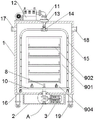
FIG. 1 is a schematic structural view of the exterior of an embodiment of the present invention;
FIG. 2 is a schematic view of the internal structure of the embodiment of the present invention;
FIG. 3 is an enlarged view at A in FIG. 2;
FIG. 4 is a schematic view of a turret in an embodiment of the utility model;
in the figure: 1-body, 2-installation bin, 3-motor, 4-drive bevel gear, 5-first bevel gear, 6-second bevel gear, 7-hollow shaft, 8-transmission shaft, 9-rotating frame, 901-portal frame, 902-baking tray, 903-baking tray bracket, 9031-enclosure frame, 9032-mesh screen, 904-first guide wheel, 10-rotating disc, 11-rotary joint, 12-hot air blower, 13-transmission pipe, 14-three-way joint, 15-blast pipe, 16-second guide wheel, 17-air inlet, 18-air outlet and 19-roller.
Detailed Description
In order to make the objects, technical solutions and advantages of the embodiments of the present invention clearer, the technical solutions in the embodiments of the present invention will be clearly and completely described below with reference to the drawings in the embodiments of the present invention, and it is obvious that the described embodiments are some, but not all, embodiments of the present invention. All other embodiments, which can be derived by a person skilled in the art from the embodiments given herein without making any creative effort, shall fall within the protection scope of the present invention.
Referring to fig. 1 to 3, an air supply device for a fragrance enhancing machine comprises a body 1, a mounting bin 2 is arranged at the bottom of the body 1, a motor 3 is arranged inside the mounting bin 2, a driving bevel gear 4 is arranged at the output end of the motor 3, a first bevel gear 5 is engaged and connected at the upper end of the driving bevel gear 4, a second bevel gear 6 is engaged and connected at the lower end of the driving bevel gear 4, a hollow shaft 7 is fixedly installed on the first bevel gear 5, the hollow shaft 7 is rotatably connected with the bottom side of the body 1, the upper end of the hollow shaft 7 penetrates into the body 1, a transmission shaft 8 is fixedly installed in the second bevel gear 6, the bottom end of the transmission shaft 8 is rotatably connected to the mounting bin 2, the upper end of the transmission shaft 8 penetrates out of the hollow shaft 7 and is fixedly installed with a rotating frame 9, a rotating disc 10 is fixedly installed at the upper end of the hollow shaft 7, a rotating joint 11 is arranged at the top of the body 1, the input end of the rotating joint 11 is connected with the output end of a hot air blower 12, the output end of the rotary joint 11 is rotatably connected with a transmission pipe 13, the other end of the transmission pipe 13 is connected with a three-way joint 14, the other two ends of the three-way joint 14 are fixedly provided with air supply pipes 15, the vertical side pipe wall of the air supply pipe 15 is equidistantly provided with a plurality of air outlets, and the bottom ends of the two groups of air supply pipes 15 are fixedly arranged on the turntable 10.
Referring to fig. 3, the rotating frame 9 includes a gantry 901, a baking pan 902 and baking pan brackets 903, the baking pan brackets 903 are fixedly installed in the gantry 901 at equal intervals, the baking pan 902 is placed on the baking pan brackets 903, and the upper end of the transmission shaft 8 is fixedly connected to the middle of the bottom surface of a group of baking pan brackets 903 arranged at the lowermost end of the gantry 901.
Referring to fig. 3, the tray 903 is composed of a surrounding frame 9031 and a mesh screen 9032, two side edges of the surrounding frame 9031 are fixedly installed on the portal frame 901, and the mesh screen 9032 is fixedly installed at the bottom of the surrounding frame 9031.
Referring to fig. 1, in order to enable the rotating rack 9 to rotate stably, the rotating rack 9 further includes a first guide wheel 904, and the first guide wheel 904 is fixedly installed on the bottom surface of the baking pan bracket 903 in the lowest end group.
Referring to fig. 1, in order to make the two sets of air supply pipes 15 and the rotary plate 10 rotate smoothly inside the main body 1, a second guide wheel 16 is fixedly installed on the bottom surface of the rotary plate 10.
Referring to fig. 1, in order to circulate the air in the device body 1, an air inlet 17 and an air outlet 18 are respectively arranged at the upper ends of the two sides of the device body 1; in order to facilitate the moving and carrying of the whole device, four rollers 19 are symmetrically and fixedly mounted at four corners of the edge of the bottom surface of the body 1.
When the utility model is used, firstly, the material to be baked and aroma-enhanced is placed on the baking pan 902, then the door of the device body 1 is closed and the motor 3 and the air heater 12 are started, the motor 3 drives the drive bevel gear 4 to rotate, the drive bevel gear 4 drives the first bevel gear 5 and the second bevel gear 6 which are meshed and connected with the drive bevel gear 4 to respectively rotate in opposite directions, the first bevel gear 5 drives the hollow shaft 7 and the turntable 10 to rotate, the second bevel gear 6 drives the transmission shaft 8 and the rotating frame 9 to rotate in the other direction which is opposite to the rotating direction of the first bevel gear 5, the hot air blown out from the air heater 12 sequentially passes through the rotating joint 11, the transmission pipe 13 and the three-way joint 14 for transmission, finally, the hot air is continuously blown out from the air outlet arranged on the air supply pipe 15 to the interior of the body 1, and continuously rotates around the hollow shaft 7 along with the driving of the turntable 10, so that the air supply pipe 15 can carry out rotary air in the interior of the body 1 around the rotating frame 9 which the material is continuously placed, thereby the materials in the fragrance extracting machine can be dried more fully and uniformly. After the process of baking and aroma raising of the materials is finished, the baking pans 902 placed on the baking pan brackets 903 of the rotating frame 9 are directly taken out, and the materials are quickly taken out.
The control mode of the motor 3 and the hot air blower 12 is controlled by a peripheral controller matched with the motor, the control circuit in the structure belongs to the common knowledge in the field, each element is only used without improvement, an embedded control mode algorithm also belongs to the content which can be realized by simple programming of a person skilled in the field, and the device is mainly used for baking and aroma raising, so the control mode and the circuit connection are not explained in detail in the utility model.
The above examples are only intended to illustrate the technical solution of the present invention, but not to limit it; although the present invention has been described in detail with reference to the foregoing embodiments, it will be understood by those of ordinary skill in the art that: the technical solutions described in the foregoing embodiments may still be modified, or some technical features may be equivalently replaced; and such modifications or substitutions do not depart from the spirit and scope of the corresponding technical solutions of the embodiments of the present invention.
Claims (7)
1. The utility model provides an air supply arrangement of fragrance machine, includes body (1), its characterized in that: the bottom of the body (1) is provided with an installation bin (2), a motor (3) is arranged in the installation bin (2), the output end of the motor (3) is provided with a drive bevel gear (4), the upper end of the drive bevel gear (4) is connected with a first bevel gear (5) in a meshing manner, the lower end of the drive bevel gear (4) is connected with a second bevel gear (6) in a meshing manner, the first bevel gear (5) is fixedly provided with a hollow shaft (7), the hollow shaft (7) is rotatably connected with the bottom side of the body (1), the upper end of the hollow shaft penetrates into the body (1), a transmission shaft (8) is fixedly arranged in the second bevel gear (6), the bottom end of the transmission shaft (8) is rotatably connected onto the installation bin (2), the upper end of the transmission shaft (8) penetrates out of the hollow shaft (7) and is fixedly provided with a rotating frame (9), hollow shaft (7) upper end fixed mounting has carousel (10), body (1) top is provided with rotary joint (11), rotary joint (11) input is connected with the output of air heater (12), it is connected with transmission pipe (13) to rotate on rotary joint (11) output, the transmission pipe (13) other end is connected with three way connection (14), three way connection (14) other both ends fixed mounting has blast pipe (15), the air outlet has been seted up on blast pipe (15) perpendicular side pipe wall, and is two sets of blast pipe (15) bottom fixed mounting is in on carousel (10).
2. The air supply device of the fragrance enhancing machine according to claim 1, characterized in that: the rotating frame (9) comprises a portal frame (901), baking pans (902) and baking pan brackets (903), the baking pan brackets (903) are fixedly installed in the portal frame (901) at equal intervals, the baking pans (902) are placed on the baking pan brackets (903), and the upper ends of the transmission shafts (8) are fixedly connected to the middle parts of the bottom surfaces of a group of baking pan brackets (903) arranged at the lowest end of the portal frame (901).
3. The air supply device of the fragrance enhancing machine according to claim 2, characterized in that: the baking pan bracket (903) is composed of a surrounding and blocking frame (9031) and a mesh screen (9032), two side edges of the surrounding and blocking frame (9031) are fixedly installed on the portal frame (901), and the mesh screen (9032) is fixedly installed at the bottom of the surrounding and blocking frame (9031).
4. The air supply device of the fragrance enhancing machine according to claim 2, characterized in that: the rotating frame (9) further comprises a first guide wheel (904), and the first guide wheel (904) is fixedly arranged on the bottom surface of the baking pan bracket (903) of the lowest end group.
5. The air supply device of the fragrance enhancing machine according to claim 1, characterized in that: and a second guide wheel (16) is fixedly arranged on the bottom surface of the rotary table (10).
6. The air supply device of the fragrance enhancing machine according to claim 1, characterized in that: the upper ends of the two sides of the body (1) are respectively provided with an air inlet (17) and an air outlet (18).
7. The air supply device of the fragrance enhancing machine according to claim 1, characterized in that: the four corners of the bottom edge of the body (1) are symmetrically and fixedly provided with rollers (19).
Priority Applications (1)
| Application Number | Priority Date | Filing Date | Title |
|---|---|---|---|
| CN202121896899.1U CN216453270U (en) | 2021-08-13 | 2021-08-13 | Air supply device of fragrance extracting machine |
Applications Claiming Priority (1)
| Application Number | Priority Date | Filing Date | Title |
|---|---|---|---|
| CN202121896899.1U CN216453270U (en) | 2021-08-13 | 2021-08-13 | Air supply device of fragrance extracting machine |
Publications (1)
| Publication Number | Publication Date |
|---|---|
| CN216453270U true CN216453270U (en) | 2022-05-10 |
Family
ID=81431967
Family Applications (1)
| Application Number | Title | Priority Date | Filing Date |
|---|---|---|---|
| CN202121896899.1U Active CN216453270U (en) | 2021-08-13 | 2021-08-13 | Air supply device of fragrance extracting machine |
Country Status (1)
| Country | Link |
|---|---|
| CN (1) | CN216453270U (en) |
-
2021
- 2021-08-13 CN CN202121896899.1U patent/CN216453270U/en active Active
Similar Documents
| Publication | Publication Date | Title |
|---|---|---|
| CN207076602U (en) | A kind of coating equipment | |
| CN103431092A (en) | Fermentation, drying and fragrance enhancement all-in-one machine for black tea | |
| CN216453270U (en) | Air supply device of fragrance extracting machine | |
| CN206809188U (en) | A kind of double door heated air circulation insulation cabinet | |
| CN205451936U (en) | Enameled wire drying equipment | |
| CN213873703U (en) | Trolley tunnel sectional type air energy heat pump dryer | |
| CN215638518U (en) | Hubei fritillary bulb drying-machine for medicinal material | |
| CN215176678U (en) | Constant temperature blast air drying cabinet | |
| CN108125322A (en) | A kind of drying shoes equipment of shoemaking station-service | |
| CN219264837U (en) | Electrothermal blowing drying box | |
| CN113414078A (en) | Heating device and inflation valve baking equipment | |
| CN208936746U (en) | A kind of self-service apparatus for baking of lift | |
| CN215030784U (en) | Interior coating drying furnace is used in metal packaging container processing | |
| CN214537223U (en) | Baking device for electronic components | |
| CN207280145U (en) | A kind of TN liquid crystal display drying bakers of temperature-adjustable | |
| CN215337536U (en) | Heated air circulation oven device | |
| CN207091765U (en) | A kind of clothes drying unit | |
| CN214211184U (en) | Hardware processing is with drying device that sprays paint | |
| CN220187307U (en) | Energy-saving drying cabinet for chemical products | |
| CN207912208U (en) | A kind of drying shoes equipment of shoemaking station-service | |
| CN215587039U (en) | Novel intelligent robot spraying of environmental protection dries device | |
| CN216694237U (en) | Hot air circulation box for gibberellic acid production | |
| CN220590604U (en) | Oven for processing plastic floor | |
| CN220728754U (en) | Tea dryer | |
| CN220321888U (en) | Acrylic plate baking equipment |
Legal Events
| Date | Code | Title | Description |
|---|---|---|---|
| GR01 | Patent grant | ||
| GR01 | Patent grant |