CN216381461U - Adjustable supporting system for mine foundation pit - Google Patents
Adjustable supporting system for mine foundation pit Download PDFInfo
- Publication number
- CN216381461U CN216381461U CN202122896652.6U CN202122896652U CN216381461U CN 216381461 U CN216381461 U CN 216381461U CN 202122896652 U CN202122896652 U CN 202122896652U CN 216381461 U CN216381461 U CN 216381461U
- Authority
- CN
- China
- Prior art keywords
- plate
- fixedly connected
- base
- bevel gear
- foundation pit
- Prior art date
- Legal status (The legal status is an assumption and is not a legal conclusion. Google has not performed a legal analysis and makes no representation as to the accuracy of the status listed.)
- Active
Links
- 210000001503 joint Anatomy 0.000 claims abstract description 26
- 230000002457 bidirectional effect Effects 0.000 claims abstract description 16
- 238000013016 damping Methods 0.000 claims description 6
- 230000035939 shock Effects 0.000 claims description 4
- 230000003139 buffering effect Effects 0.000 claims 2
- 238000010521 absorption reaction Methods 0.000 claims 1
- 239000000463 material Substances 0.000 abstract description 4
- 238000009434 installation Methods 0.000 abstract description 3
- 238000005381 potential energy Methods 0.000 description 5
- 238000000034 method Methods 0.000 description 4
- 238000003032 molecular docking Methods 0.000 description 3
- 230000003014 reinforcing effect Effects 0.000 description 3
- 230000006835 compression Effects 0.000 description 2
- 238000007906 compression Methods 0.000 description 2
- 238000001125 extrusion Methods 0.000 description 2
- 238000012986 modification Methods 0.000 description 2
- 230000004048 modification Effects 0.000 description 2
- 239000002689 soil Substances 0.000 description 2
- 230000009286 beneficial effect Effects 0.000 description 1
- 238000010276 construction Methods 0.000 description 1
- 230000008602 contraction Effects 0.000 description 1
- 230000007547 defect Effects 0.000 description 1
- 230000000694 effects Effects 0.000 description 1
- 238000003780 insertion Methods 0.000 description 1
- 230000037431 insertion Effects 0.000 description 1
- 230000002787 reinforcement Effects 0.000 description 1
- 239000011435 rock Substances 0.000 description 1
- 239000000126 substance Substances 0.000 description 1
Images


Landscapes
- Foundations (AREA)
Abstract
The utility model discloses an adjustable supporting system for a mine foundation pit, which comprises: the base is used as a supporting base of the device, an inter-moving frame is connected in the base, and the other end of the top beam is connected with a front beam; the threaded hole is formed in the back of the transverse plate, a bidirectional screw rod is connected to the threaded hole in a threaded mode, the bidirectional screw rod is connected into the bearing seat, one side of the driving bevel gear is connected with a handle, and the handle is rotatably connected to the inner side wall of the groove. This supporting system with adjustable mine foundation ditch through two-way lead screw rotation, makes two sets of diaphragms outwards remove simultaneously, increases the support area of base, makes the base stablely support subaerial more, and is flexible through hydraulic stem and buffer spring, slows down the impact force that the material dropped and received on the guard plate, and then protects the back timber, and through when inserting the stand in the sleeve, makes the inserted bar insert the butt joint intracavity, and then fixes the stand end in the sleeve to be convenient for dock the installation stand.
Description
Technical Field
The utility model relates to the technical field of mine foundation pits, in particular to an adjustable supporting system for a mine foundation pit.
Background
The foundation pit is a soil pit excavated at a foundation design position according to the base elevation and the base plane size, a supporting device is required to be used in the mine foundation pit to support the foundation pit, and the existing mine foundation pit supporting system has certain defects when in use, such as the above;
according to the foundation pit supporting system disclosed by the publication number CN204825921U, the supporting structure formed by combining the supporting piles and the enclosing purlin beams is arranged at the side wall of the foundation pit, the reinforcing piles are arranged in the soil body outside the foundation pit, and the supporting piles and the reinforcing piles are tensioned by the tie pieces, so that the supporting form of double-row piles can be formed, the supporting strength and the supporting rigidity of the side wall of the foundation pit are improved, the deformation of the foundation pit can be reduced, the reinforcing piles are arranged outside the foundation pit, the construction space in the foundation pit cannot be occupied, and the problem that inner support reinforcement cannot be adopted in the foundation pit supporting engineering can be solved;
this prior art solution also presents the following problems when in use:
1. the supporting area is not convenient to adjust;
2. the top beam is inconvenient to protect;
3. the upright posts are not convenient to butt joint and install;
improvements are needed to address the above problems.
SUMMERY OF THE UTILITY MODEL
The utility model aims to provide an adjustable supporting system for a mine foundation pit, and aims to solve the problems that the supporting area of the existing mine foundation pit supporting system in the market is inconvenient to adjust, a top beam is inconvenient to protect and upright columns are inconvenient to butt joint.
In order to achieve the purpose, the utility model provides the following technical scheme: an adjustable supporting system for a mine foundation pit comprises:
the device comprises a base, a front beam, a back beam, a front beam, a transverse beam, a base, a beam, a base, a beam, a base, a beam, a base, a beam, a base, a beam;
the groove is formed below the base, a limiting groove is formed above the inner portion of the groove, a guide plate is connected in the limiting groove in a sliding mode, and a transverse plate is fixedly connected below the guide plate;
the screw hole is seted up the diaphragm back, screw hole female connection has two-way lead screw, two-way lead screw is connected in the bearing frame, bearing frame fixed connection is in the recess top, it is connected with driven bevel gear to inlay on the two-way lead screw, driven bevel gear one side meshing is connected with initiative bevel gear, initiative bevel gear one side is connected with the handle, the handle rotates to be connected on the recess inside wall.
Preferably, the transverse plates, the bidirectional screw rod, the bearing seats, the driven bevel gears and the driving bevel gears form a linkage structure, a group of transverse plates are arranged at two ends of the bidirectional screw rod respectively, the two groups of transverse plates move outwards simultaneously through rotation of the bidirectional screw rod, the supporting area of the base is increased, and the base is supported on the ground more stably.
Preferably, the top beam includes:
the damping plate is fixedly connected above the top beam, a hydraulic rod is fixedly connected above the damping plate, a protection plate is fixedly connected to the top end of the hydraulic rod, a buffer spring is fixedly connected to the hydraulic rod, and the top end of the buffer spring is fixedly connected below the protection plate;
the fixture block is fixedly connected to one side of the protection plate, the fixture block is connected to the inside of the guide groove in a clamped mode, the guide groove is formed in one side of the vertical plate, the vertical plate is fixedly connected to the upper portion of the top beam, the hydraulic rod and the buffer spring stretch out and draw back, impact force caused when the material drops on the protection plate is relieved, and then the top beam is protected.
Preferably, the hydraulic rod and the buffer spring are respectively provided with a group at four corners above the damping plate, and the height of the guide groove is smaller than that of the vertical plate, so that the clamping block is pushed to be punched out of the guide groove when the buffer spring is prevented from rebounding.
Preferably, the pillar includes:
the butt joint chamber is seted up stand one side, the butt joint intracavity is connected with the inserted bar, inserted bar one end fixedly connected with baffle, baffle one side fixedly connected with pressure spring, pressure spring one end fixed connection is placing the intracavity, it sets up on the sleeve inner wall to place the chamber, the muffjoint is in pushing jack one end, and through inserting the stand in the sleeve, make the inserted bar insert the butt joint intracavity, and then fix the stand end in the sleeve to be convenient for dock installation stand.
Preferably, the lengths of the inserted bar, the baffle and the pressure spring are greater than the sum of the depths of the butt joint cavity and the placing cavity, and the depth of the butt joint cavity is less than that of the inserted bar, so that the baffle is not separated from the placing cavity while the inserted bar can be firmly inserted into the butt joint cavity.
Compared with the prior art, the utility model has the beneficial effects that: this supporting system with adjustable mine foundation ditch through two-way lead screw rotation, makes two sets of diaphragms outwards remove simultaneously, increases the support area of base, makes the base stablely support subaerial more, and is flexible through hydraulic stem and buffer spring, slows down the impact force that the material dropped and received on the guard plate, and then protects the back timber, and through when inserting the stand in the sleeve, makes the inserted bar insert the butt joint intracavity, and then fixes the stand end in the sleeve to be convenient for dock the installation stand.
1. When the device is used, the device is moved to a specific position, then the handle is rotated, the handle drives the driving bevel gear to rotate, the driving bevel gear drives the driven bevel gear to rotate while rotating, the driven bevel gear drives the bidirectional screw rod to rotate through the bearing seat, the bidirectional screw rod drives the two groups of transverse plates to move outwards through the action of the limiting grooves and the guide plates while rotating, the supporting area of the base is increased, and the device is further convenient to stably support on the ground;
2. when the buffer spring recovers deformation, the elastic potential energy is released to drive the protection plate to rise again, so that the fixture block moves along the guide groove again to attenuate the elastic potential energy, and the process is repeated continuously until the impact force is completely offset, so that the top beam is protected and the top beam is prevented from being damaged;
3. at first, correspond five groups's butt joint chambeies outside the stand with the inside five inserted bars of sleeve, then insert the stand end in the sleeve, at the male in-process, the stand lateral wall can extrude five groups' inserted bars simultaneously, when the inserted bar receives the extrusion, can be to placing the intracavity and removing, drive baffle extrusion pressure spring, when the stand end inserts in the sleeve completely, the position of five groups's inserted bar coincides with the position of five groups's butt joint chambeies, the inserted bar resets rapidly under the effect of pressure spring, drive the inserted bar and insert the butt joint intracavity, fix the stand in the sleeve, thereby be convenient for butt joint equipment stand.
Drawings
FIG. 1 is a schematic structural view of the present invention;
FIG. 2 is a schematic view of a two-way screw according to the present invention;
FIG. 3 is a schematic view of the sleeve structure of the present invention;
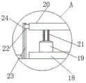
fig. 4 is an enlarged view of the structure of part a of the present invention.
In the figure: 1. a base; 2. moving the frames mutually; 3. pushing a jack; 4. a column; 5. a top beam; 6. covering the beam; 7. a front beam; 8. a groove; 9. a limiting groove; 10. a guide plate; 11. a transverse plate; 12. a threaded hole; 13. a bidirectional screw rod; 14. a bearing seat; 15. a driven bevel gear; 16. a drive bevel gear; 17. a handle; 18. a damper plate; 19. a hydraulic lever; 20. a protection plate; 21. a buffer spring; 22. a clamping block; 23. a guide groove; 24. a vertical plate; 25. a docking chamber; 26. inserting a rod; 27. a baffle plate; 28. a pressure spring; 29. a placement chamber; 30. a sleeve.
Detailed Description
The technical solutions in the embodiments of the present invention will be clearly and completely described below with reference to the drawings in the embodiments of the present invention, and it is obvious that the described embodiments are only a part of the embodiments of the present invention, and not all of the embodiments. All other embodiments, which can be derived by a person skilled in the art from the embodiments given herein without making any creative effort, shall fall within the protection scope of the present invention.
Referring to fig. 1-4, the present invention provides a technical solution: an adjustable supporting system for a mine foundation pit comprises: the device comprises a base 1 serving as a supporting base of the device, a mutual-moving frame 2 is connected in the base 1, a pushing jack 3 is connected above the base 1, an upright post 4 is arranged at one end of the pushing jack 3, a top beam 5 is connected at the top end of the upright post 4, a shield beam 6 is connected at one end of the top beam 5, a front beam 7 is connected at the other end of the top beam 5, a groove 8 is formed below the base 1, a limit groove 9 is formed above the inner part of the groove 8, a guide plate 10 is connected in the limit groove 9 in a sliding manner, a transverse plate 11 is fixedly connected below the guide plate 10, a threaded hole 12 is formed in the back of the transverse plate 11, a bidirectional screw rod 13 is connected in the threaded hole 12 in a threaded manner, the bidirectional screw rod 13 is connected in a bearing seat 14, the bearing seat 14 is fixedly connected above the groove 8, a driven bevel gear 15 is embedded and connected on the bidirectional screw rod 13, a driving bevel gear 16 is meshed and connected on one side of the driven bevel gear 15, a handle 17 is connected on one side of the driving bevel gear 16, the handle 17 is rotatably connected to the inner side wall of the groove 8.
The transverse plates 11, the bidirectional screw rods 13, the bearing seats 14, the driven bevel gears 15 and the driving bevel gears 16 form a linkage structure, a group of transverse plates 11 are respectively arranged at two ends of each bidirectional screw rod 13, and the two groups of transverse plates 11 simultaneously move outwards through rotation of the bidirectional screw rods 13, so that the supporting area of the base 1 is increased, and the base 1 is more stably supported on the ground.
The top beam 5 includes: shock attenuation board 18, fixed connection is in back timber 5 top, 18 top fixedly connected with hydraulic stem 19 of shock attenuation board, 19 top fixedly connected with guard plates 20 of hydraulic stem, fixedly connected with buffer spring 21 on the hydraulic stem 19, 21 top fixed connections of buffer spring are in guard plates 20 below, fixture block 22, fixed connection is in guard plates 20 one side, fixture block 22 block is connected in guide way 23, guide way 23 is seted up in riser 24 one side, 24 fixed connection of riser are in back timber 5 top. Hydraulic stem 19 and buffer spring 21 are provided with a set ofly respectively on the four corners of shock attenuation board 18 top, and the height of guide way 23 is less than the height of riser 24, when preventing buffer spring 21 resilience, promotes fixture block 22 and dashes out of guide way 23. Through the extension and contraction of the hydraulic rod 19 and the buffer spring 21, the impact force of falling of the materials on the protection plate 20 is relieved, and then the top beam 5 is protected.
The column 4 includes: butt joint chamber 25, offer in stand 4 one side, butt joint chamber 25 in-connection has inserted bar 26, inserted bar 26 one end fixedly connected with baffle 27, baffle 27 one side fixedly connected with pressure spring 28, pressure spring 28 one end fixed connection is in placing chamber 29, places chamber 29 and offers on sleeve 30 inner wall, and sleeve 30 connects in 3 one ends of advancing jack. The lengths of the inserted rod 26, the baffle 27 and the pressure spring 28 are greater than the sum of the depths of the butt joint cavity 25 and the placing cavity 29, and the depth of the butt joint cavity 25 is less than the length of the inserted rod 26, so that the inserted rod 26 can be firmly inserted into the butt joint cavity 25, and the baffle 27 is not separated from the placing cavity 29. The end of the post 4 is secured within the sleeve 30 by inserting the post 4 into the sleeve 30 while simultaneously inserting the post 26 into the docking cavity 25, thereby facilitating docking of the post 4.
The working principle is as follows: as shown in fig. 1-4, when using the adjustable supporting system for mine foundation pit, the device is simply known, firstly, the five groups of butt joint cavities 25 at the outer side of the upright post 4 correspond to the five groups of inserted rods 26 in the sleeve 30, then the tail end of the upright post 4 is inserted into the sleeve 30, in the process of insertion, the outer side wall of the upright post 4 simultaneously extrudes the five groups of inserted rods 26, the inserted rods 26 move into the placing cavity 29 when being extruded, the baffle plate 27 is driven to extrude the compression spring 28, when the tail end of the upright post 4 is completely inserted into the sleeve 30, the position of the five groups of inserted rods 26 is coincided with the position of the five groups of butt joint cavities 25, the inserted rods 26 are quickly reset under the action of the compression spring 28, the inserted rods 26 are driven to be inserted into the butt joint cavities 25, the upright post 4 is fixed in the sleeve 30, thereby facilitating the assembly of the upright post 4, secondly, when in use, the device is moved to a specific position, then the handle 17 is rotated, the handle 17 drives the driving bevel gear 16 to rotate, the driving bevel gear 16 drives the driven bevel gear 15 to rotate while rotating, the driven bevel gear 15 drives the two-way screw rod 13 to rotate through the bearing seat 14, the two-way screw rod 13 drives the two groups of transverse plates 11 to move outwards while rotating through the action of the limiting groove 9 and the guide plate 10, the supporting area of the base 1 is increased, and then the two-way screw rod is conveniently and stably supported on the ground, when falling rocks or other substances fall off during supporting, the two-way screw rod can be in contact with the protection plate 20, when the protection plate 20 is impacted, the two-way screw rod can move downwards, the hydraulic rod 19 is extruded, the buffer spring 21 can be compressed while the hydraulic rod 19 contracts, a part of impact force is converted into elastic potential energy to be stored, meanwhile, the fixture block 22 moves in the guide groove 23 along with the movement of the protection plate 20, a part of the impact force is converted into friction force, and the damping plate 18 can deform, when the buffer spring 21 recovers to deform, the elastic potential energy is released to drive the protection plate 20 to ascend again, so that the fixture block 22 moves along the guide groove 23 again to attenuate the elastic potential energy, and the process is repeated continuously until the impact force is completely offset, so as to protect the top beam 5 and prevent the top beam 5 from being damaged.
Although the present invention has been described in detail with reference to the foregoing embodiments, it will be apparent to those skilled in the art that various changes in the embodiments and modifications of the utility model can be made, and equivalents and modifications of some features of the utility model can be made without departing from the spirit and scope of the utility model.
Claims (6)
1. The utility model provides a supporting system with adjustable mine foundation ditch which characterized in that includes:
the device comprises a base (1), wherein an inter-moving frame (2) is connected in the base (1), a pushing jack (3) is connected above the base (1), an upright post (4) is arranged at one end of the pushing jack (3), a top beam (5) is connected at the top end of the upright post (4), one end of the top beam (5) is connected with a shield beam (6), and the other end of the top beam (5) is connected with a front beam (7);
the groove (8) is formed below the base (1), a limiting groove (9) is formed in the upper portion inside the groove (8), a guide plate (10) is connected in the limiting groove (9) in a sliding mode, and a transverse plate (11) is fixedly connected below the guide plate (10);
screw hole (12) are seted up diaphragm (11) back, screw hole (12) female connection has two-way lead screw (13), two-way lead screw (13) are connected in bearing frame (14), bearing frame (14) fixed connection is in recess (8) top, inlay on two-way lead screw (13) and establish being connected with driven bevel gear (15), driven bevel gear (15) one side meshing is connected with drive bevel gear (16), drive bevel gear (16) one side is connected with handle (17), handle (17) rotate to be connected on recess (8) inside wall.
2. The adjustable support system for the mine foundation pit according to claim 1, wherein: the transverse plate (11), the bidirectional screw rod (13), the bearing seat (14), the driven bevel gear (15) and the driving bevel gear (16) form a linkage structure, and the transverse plate (11) is provided with a group at two ends of the bidirectional screw rod (13).
3. The adjustable support system for the mine foundation pit according to claim 1, wherein: the top beam (5) comprises:
the damping plate (18) is fixedly connected above the top beam (5), a hydraulic rod (19) is fixedly connected above the damping plate (18), a protection plate (20) is fixedly connected to the top end of the hydraulic rod (19), a buffering spring (21) is fixedly connected to the hydraulic rod (19), and the top end of the buffering spring (21) is fixedly connected below the protection plate (20);
the clamping block (22) is fixedly connected to one side of the protection plate (20), the clamping block (22) is clamped and connected in the guide groove (23), the guide groove (23) is formed in one side of the vertical plate (24), and the vertical plate (24) is fixedly connected to the upper portion of the top beam (5).
4. The adjustable supporting system for the mine foundation pit according to claim 3, wherein: the hydraulic rods (19) and the buffer springs (21) are respectively provided with one group at four corners above the shock absorption plate (18), and the height of the guide groove (23) is smaller than that of the vertical plate (24).
5. The adjustable support system for the mine foundation pit according to claim 1, wherein: the upright (4) comprises:
butt joint chamber (25), set up stand (4) one side, butt joint chamber (25) in-connection has inserted bar (26), inserted bar (26) one end fixedly connected with baffle (27), baffle (27) one side fixedly connected with pressure spring (28), pressure spring (28) one end fixed connection is in placing chamber (29), place chamber (29) and set up on sleeve (30) inner wall, sleeve (30) are connected and are being passed jack (3) one end.
6. The adjustable supporting system for the mine foundation pit according to claim 5, wherein: the length of the inserted rod (26), the length of the baffle plate (27) and the length of the pressure spring (28) are greater than the sum of the internal depth of the butt joint cavity (25) and the internal depth of the placing cavity (29), and the internal depth of the butt joint cavity (25) is less than the length of the inserted rod (26).
Priority Applications (1)
| Application Number | Priority Date | Filing Date | Title |
|---|---|---|---|
| CN202122896652.6U CN216381461U (en) | 2021-11-24 | 2021-11-24 | Adjustable supporting system for mine foundation pit |
Applications Claiming Priority (1)
| Application Number | Priority Date | Filing Date | Title |
|---|---|---|---|
| CN202122896652.6U CN216381461U (en) | 2021-11-24 | 2021-11-24 | Adjustable supporting system for mine foundation pit |
Publications (1)
| Publication Number | Publication Date |
|---|---|
| CN216381461U true CN216381461U (en) | 2022-04-26 |
Family
ID=81218364
Family Applications (1)
| Application Number | Title | Priority Date | Filing Date |
|---|---|---|---|
| CN202122896652.6U Active CN216381461U (en) | 2021-11-24 | 2021-11-24 | Adjustable supporting system for mine foundation pit |
Country Status (1)
| Country | Link |
|---|---|
| CN (1) | CN216381461U (en) |
-
2021
- 2021-11-24 CN CN202122896652.6U patent/CN216381461U/en active Active
Similar Documents
| Publication | Publication Date | Title |
|---|---|---|
| CN106948851A (en) | A kind of alley hydraulic support | |
| CN216381461U (en) | Adjustable supporting system for mine foundation pit | |
| CN214784869U (en) | Basement post-cast strip waterproof construction | |
| CN208153024U (en) | It is a kind of with prevent tunnel perimeter convergence and vault sinking support protection mechanism | |
| CN219653722U (en) | Foundation pit supporting device capable of effectively preventing foundation pit from collapsing | |
| CN209082541U (en) | A kind of communication tower equipped with prefabricated pile basis | |
| CN112392527B (en) | Anti-impact coal mine supporting frame and using method | |
| CN215441940U (en) | Adjustable support connecting piece | |
| CN214273538U (en) | Energy-saving lifting anchoring drilling machine | |
| CN113323034A (en) | Auxiliary device for automatically correcting deviation and automatically alarming for building foundation construction | |
| CN213175020U (en) | Structure is built to antidetonation room | |
| CN213508548U (en) | Novel foundation structure | |
| CN211547621U (en) | Buffer of beam pier of municipal administration bridge | |
| CN211597849U (en) | Building templates for building engineering | |
| CN210369995U (en) | Shockproof correcting structure for building | |
| CN219908979U (en) | Maintenance structure for building construction | |
| CN211922687U (en) | Novel pressure-reducing anti-seismic building foundation | |
| CN210686825U (en) | Tower crane base | |
| CN115030761B (en) | Tunnel portal supporting equipment for preventing impact of earthquake landslide and rockfall and using method | |
| CN221663560U (en) | Water retaining device for hydraulic engineering construction | |
| CN220746996U (en) | Construction elevator foundation structure on backfill soil | |
| CN221372145U (en) | Civil engineering construction is with antidetonation formula reinforcing building stake | |
| CN215443915U (en) | Rotary spraying anchoring drilling machine chassis assembly with amplitude variation function | |
| CN112323964B (en) | Environment-friendly prefabricated house and assembly scheme thereof | |
| CN216379491U (en) | Foundation pile for hydraulic engineering building |
Legal Events
| Date | Code | Title | Description |
|---|---|---|---|
| GR01 | Patent grant | ||
| GR01 | Patent grant | ||
| PE01 | Entry into force of the registration of the contract for pledge of patent right |
Denomination of utility model: An adjustable support system for mining foundation pits Granted publication date: 20220426 Pledgee: Shandong Tengzhou rural commercial bank Limited by Share Ltd. SME branch Pledgor: Shandong Fengyuan Hongke Equipment Technology Co.,Ltd. Registration number: Y2024980009999 |
|
| PE01 | Entry into force of the registration of the contract for pledge of patent right |