CN216367737U - A feed proportioning system for organic compound fertilizer - Google Patents
A feed proportioning system for organic compound fertilizer Download PDFInfo
- Publication number
- CN216367737U CN216367737U CN202122554013.1U CN202122554013U CN216367737U CN 216367737 U CN216367737 U CN 216367737U CN 202122554013 U CN202122554013 U CN 202122554013U CN 216367737 U CN216367737 U CN 216367737U
- Authority
- CN
- China
- Prior art keywords
- fixedly connected
- box
- compound fertilizer
- organic compound
- conical disc
- Prior art date
- Legal status (The legal status is an assumption and is not a legal conclusion. Google has not performed a legal analysis and makes no representation as to the accuracy of the status listed.)
- Active
Links
Images


Abstract
The utility model discloses a batching system for organic compound fertilizer, which comprises a supporting block, wherein the top of the supporting block is fixedly connected with a second box body, the inside of the second box body is movably connected with a filtering component, the bottom of the second box body is fixedly connected with a discharging pipe, the top of the second box body is fixedly connected with a first box body, and the top of the first box body is fixedly provided with a first motor. According to the utility model, the filtering component is movably connected in the second box body, the second motor can be used for driving the first grinding wheel to rotate, the first grinding wheel rotates to drive the second grinding wheel to rotate, the raw materials after stirring and mixing are ground, the mixing efficiency is further improved, meanwhile, the ground raw materials fall on the filter screen, larger solid matters existing in the raw materials are removed by using the filter screen, the output end of the electric push rod drives the movable plate to move, and the movable plate moves to drive the filter screen to move up and down, so that the filter screen is prevented from being blocked, and the screening effect of the filter screen is ensured.
Description
Technical Field
The utility model relates to the technical field of compound fertilizer production equipment, in particular to a batching system for an organic compound fertilizer.
Background
The compound fertilizer is a chemical fertilizer containing two or more nutrient elements, has the advantages of high nutrient content, few side components, good physical properties and the like, has very important effects on balanced fertilization, improvement of the utilization rate of the fertilizer and promotion of high and stable yield of crops, wherein materials in various proportions are required to be uniformly mixed in the production process of organic compound ingredients, and in the use process, the existing ingredient system for the organic compound fertilizer has many problems or defects:
traditional feed proportioning system for organic compound fertilizer does not filter the raw materials after mixing in-service use, leads to the unable filtering of great solid matter that exists in the raw materials, has reduced the production preparation quality of compound fertilizer, simultaneously because raw materials itself has certain moisture, when in special season, the humidity of raw materials too big can produce the bonding, leads to the raw materials to mix inhomogeneous.
SUMMERY OF THE UTILITY MODEL
The utility model aims to provide a batching system for organic compound fertilizer, which aims to solve the problems in the background technology.
In order to achieve the purpose, the utility model provides the following technical scheme: the utility model provides a feed proportioning system for organic compound fertilizer, includes the supporting shoe, the top fixedly connected with second box of supporting shoe, the inside swing joint of second box has filtering component, the bottom fixedly connected with discharging pipe of second box, the first box of top fixedly connected with of second box, the top fixed mounting of first box has first motor, the output fixedly connected with stirring subassembly of first motor, the inside top swing joint of first box has stoving subassembly.
As a further scheme of the utility model: the filter assembly comprises a movable plate, a limiting sleeve is fixedly arranged at the top of the movable plate, a limiting rod is movably connected inside the limiting sleeve, an electric push rod is fixedly arranged at the bottom of the movable plate, and a filter screen is fixedly connected between the movable plates.
As a further scheme of the utility model: the top fixedly connected with guide plate of filter screen, one side fixed mounting of guide plate has the second motor, the output end fixedly connected with first grinding miller of second motor, the one end meshing of first grinding miller is connected with the second grinding miller, the top fixedly connected with unloading pipe of first grinding miller, the inside fixed mounting of unloading pipe has the unloading valve.
As a further scheme of the utility model: the drying assembly comprises a drying groove, a filter plate is fixedly connected to the top of the drying groove, a second movable rod is movably connected to the inside of the drying groove, a fan is fixedly connected to the bottom of the second movable rod, and a heating tube is fixedly connected to the bottom of the fan.
As a further scheme of the utility model: the surface of second movable rod cup joints and is connected with fourth conical disk, the top meshing of fourth conical disk is connected with third conical disk, the first movable rod of the inside fixedly connected with of third conical disk, the surface of first movable rod cup joints and is connected with first conical disk, the bottom meshing of first conical disk is connected with second conical disk.
As a further scheme of the utility model: the stirring subassembly includes the pivot, the surperficial equidistance of pivot is connected with the installation piece, the equal fixedly connected with puddler in both sides of installation piece, the equal fixedly connected with mounting panel in one side of puddler, the equal fixedly connected with scraper blade in one side of mounting panel, the top fixedly connected with inlet pipe of scraper blade, the inside fixed mounting of inlet pipe has the governing valve.
Compared with the prior art, the utility model has the beneficial effects that: this a feed proportioning system for organic compound fertilizer has following advantage:
(1) the filtering component is movably connected inside the second box body, the second motor can be used for driving the first grinding wheel to rotate, the first grinding wheel rotates to drive the second grinding wheel to rotate, the raw materials after stirring and mixing are ground, the mixing efficiency is further improved, meanwhile, the ground raw materials fall on the filter screen, larger solids existing in the raw materials are removed by using the filter screen, the output end of the electric push rod drives the movable plate to move, the movable plate moves to drive the filter screen to move up and down, the filter screen is prevented from being blocked, the screening effect of the filter screen is ensured, the problem that the larger solids existing in the raw materials cannot be filtered due to the fact that the mixed raw materials are not filtered in the prior art is solved, and the production quality of the compound fertilizer is reduced;
(2) the drying component is movably connected to the top end inside the first box body, the first motor can be used for driving the rotating shaft to rotate, the rotating shaft rotates to drive the first conical disc to rotate through the second conical disc, the first conical disc rotates to drive the third conical disc to rotate through the first movable rod, the third conical disc rotates to drive the second movable rod to rotate through the fourth conical disc, the second movable rod rotates to drive the fan to rotate, heat generated when the heating tube works is blown into the first box body through wind power generated when the fan rotates, the raw materials are dried, the raw materials are prevented from being condensed, the later-stage manufacturing quality is influenced, and the problem that the raw materials are unevenly mixed due to the fact that the raw materials have certain moisture in the prior art and the raw materials are too high in humidity and can be bonded in special seasons is solved;
(3) through the output fixedly connected with stirring subassembly at first motor, the output that can utilize first motor drives the pivot rotation, the pivot is rotatory to drive the puddler rotation through the installation piece, stir the raw materials in the first box, and the puddler is rotatory to drive the scraper blade through the mounting panel and rotate, it clears up adnexed raw materials on the first box inner wall, make the raw materials mix more evenly, install the governing valve simultaneously in the inlet tube, be convenient for adjust the rate of addition and the dose of raw materials and addition feed agent.
Drawings
FIG. 1 is a schematic structural view of the present invention;
FIG. 2 is an enlarged view of the utility model at A;
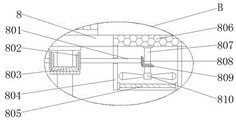
FIG. 3 is an enlarged view of the utility model at B;
FIG. 4 is a top view of a partial structure of the filter assembly of the present invention.
In the figure: 1. a first motor; 2. a stirring assembly; 201. a feed pipe; 202. mounting blocks; 203. a stirring rod; 204. adjusting a valve; 205. a rotating shaft; 206. mounting a plate; 207. a squeegee; 3. a support block; 4. a first case; 5. a second case; 6. a discharge pipe; 7. a filter assembly; 701. a limiting sleeve; 702. a limiting rod; 703. moving the plate; 704. an electric push rod; 705. a discharging pipe; 706. a discharge valve; 707. a first grinding wheel; 708. a baffle; 709. filtering with a screen; 710. a second grinding wheel; 711. a second motor; 8. a drying assembly; 801. a first movable bar; 802. a first conical disk; 803. a second conical disk; 804. a drying tank; 805. a heat generating tube; 806. filtering the plate; 807. a second movable bar; 808. a third conical disk; 809. a fourth conical disk; 810. a fan.
Detailed Description
The technical solutions in the embodiments of the present invention will be clearly and completely described below with reference to the drawings in the embodiments of the present invention, and it is obvious that the described embodiments are only a part of the embodiments of the present invention, and not all of the embodiments. All other embodiments, which can be derived by a person skilled in the art from the embodiments given herein without making any creative effort, shall fall within the protection scope of the present invention.
Referring to fig. 1-4, an embodiment of the present invention is shown: a batching system for organic compound fertilizer comprises a supporting block 3, a second box body 5 is fixedly connected to the top of the supporting block 3, a filtering component 7 is movably connected inside the second box body 5, the filtering component 7 comprises a moving plate 703, a limiting sleeve 701 is fixedly arranged on the top of the moving plate 703, a limiting rod 702 is movably connected inside the limiting sleeve 701, an electric push rod 704 is fixedly arranged at the bottom of the moving plate 703, a filter screen 709 is fixedly connected between the moving plates 703, a guide plate 708 is fixedly connected to the top of the filter screen 709, a second motor 711 is fixedly arranged on one side of the guide plate 708, a first grinding wheel 707 is fixedly connected to the output end of the second motor 711, a second grinding wheel 710 is meshed and connected to one end of the first grinding wheel 707, a discharging pipe 705 is fixedly connected to the top of the first grinding wheel 707, a discharging valve 706 is fixedly arranged inside the discharging pipe 705, and a discharging pipe 6 is fixedly connected to the bottom of the second box body 5, the top of the second box body 5 is fixedly connected with a first box body 4, and the top of the first box body 4 is fixedly provided with a first motor 1;
specifically, as shown in fig. 1, 2 and 4, when in use, the filtering assembly 7 is movably connected inside the second box 5, the second motor 711 can be used to drive the first grinding wheel 707 to rotate, the first grinding wheel 707 rotates to drive the second grinding wheel 710 to rotate, the raw materials after stirring and mixing are ground, the mixing efficiency is further improved, meanwhile, the ground raw materials fall on the filter screen 709, the filter screen 709 is used to remove large solids existing in the raw materials, the output end of the electric push rod 704 drives the moving plate 703 to move, and the moving plate 703 moves to drive the filter screen 709 to move up and down, so that the filter screen 709 is prevented from being blocked, the screening effect of the raw materials is ensured, and the problems that the mixed raw materials are not filtered conventionally, the large solids existing in the raw materials cannot be filtered, and the production quality of the compound fertilizer is reduced are solved;
the output end of the first motor 1 is fixedly connected with a stirring assembly 2, the stirring assembly 2 comprises a rotating shaft 205, the surface of the rotating shaft 205 is equidistantly connected with mounting blocks 202, two sides of the mounting blocks 202 are fixedly connected with stirring rods 203, one sides of the stirring rods 203 are fixedly connected with mounting plates 206, one sides of the mounting plates 206 are fixedly connected with scraping plates 207, the tops of the scraping plates 207 are fixedly connected with a feeding pipe 201, and the interior of the feeding pipe 201 is fixedly provided with a regulating valve 204;
specifically, as shown in fig. 1, when in use, the stirring assembly 2 is fixedly connected to the output end of the first motor 1, the output end of the first motor 1 can be utilized to drive the rotating shaft 205 to rotate, the rotating shaft 205 rotates to drive the stirring rod 203 to rotate through the mounting block 202, so as to stir the raw material in the first box 4, the stirring rod 203 rotates to drive the scraping plate 207 to rotate through the mounting plate 206, so as to clean the raw material attached to the inner wall of the first box 4, so that the raw material is mixed more uniformly, and meanwhile, the feed pipe 201 is internally provided with the regulating valve 204, so as to facilitate regulation of the adding speed and dosage of the raw material and the additive;
the top end inside the first box body 4 is movably connected with a drying component 8, the drying component 8 comprises a drying groove 804, the top of the drying groove 804 is fixedly connected with a filter plate 806, the inside of the drying groove 804 is movably connected with a second movable rod 807, the bottom of the second movable rod 807 is fixedly connected with a fan 810, the bottom of the fan 810 is fixedly connected with a heating pipe 805, the surface of the second movable rod 807 is connected with a fourth conical disc 809 in a sleeved mode, the top of the fourth conical disc 809 is connected with a third conical disc 808 in a meshed mode, the inside of the third conical disc 808 is fixedly connected with a first movable rod 801, the surface of the first movable rod 801 is connected with a first conical disc 802 in a sleeved mode, and the bottom of the first conical disc 802 is connected with a second conical disc 803 in a meshed mode;
specifically, as shown in fig. 1 and 3, when in use, the drying component 8 is movably connected to the top end inside the first box 4, the first motor 1 can be used to drive the rotating shaft 205 to rotate, the rotating shaft 205 rotates to drive the first conical disc 802 to rotate through the second conical disc 803, the first conical disc 802 rotates to drive the third conical disc 808 through the first movable rod 801 to rotate, the third conical disc 808 rotates to drive the second movable rod 807 to rotate through the fourth conical disc 809, the second movable rod 807 rotates to drive the fan 810 to rotate, heat generated when the heating tube 805 operates is blown into the first box 4 by wind power generated when the fan 810 rotates, the raw materials are dried to prevent the raw materials from being condensed, which affects the later-stage production quality, solves the problems that the traditional raw materials have certain moisture, when the humidity of the raw materials is too high in a special season, the raw materials are bonded, and the raw materials are not uniformly mixed.
The working principle is as follows: when the device is used, firstly, the filtering component 7 is movably connected inside the second box body 5, the second motor 711 can be used for driving the first grinding wheel 707 to rotate, the first grinding wheel 707 rotates to drive the second grinding wheel 710 to rotate, the raw materials after stirring and mixing are ground, the mixing efficiency is further improved, meanwhile, the ground raw materials fall on the filter screen 709, larger solid matters existing in the raw materials are removed by using the filter screen 709, the output end of the electric push rod 704 drives the moving plate 703 to move, and the moving plate 703 moves to drive the filter screen 709 to move up and down, so that the filter screen 709 is prevented from being blocked, and the screening effect of the filter screen is ensured;
secondly, a drying component 8 is movably connected to the top end inside the first box 4, the first motor 1 can be used for driving the rotating shaft 205 to rotate, the rotating shaft 205 rotates to drive the first conical disc 802 to rotate through the second conical disc 803, the first conical disc 802 rotates to drive the third conical disc 808 to rotate through the first movable rod 801, the third conical disc 808 rotates to drive the second movable rod 807 to rotate through the fourth conical disc 809, the second movable rod 807 rotates to drive the fan 810 to rotate, heat generated when the heating pipe 805 works is blown into the first box 4 by wind power generated when the fan 810 rotates, the raw material is dried, the raw material is prevented from being condensed, and the later-stage manufacturing quality is influenced;
finally, through the output fixedly connected with stirring subassembly 2 at first motor 1, the output that can utilize first motor 1 drives pivot 205 rotatory, pivot 205 is rotatory to drive puddler 203 rotatory through installation piece 202, stir the raw materials in first box 4, and puddler 203 is rotatory to drive scraper blade 207 through mounting panel 206 and rotates, it clears up adnexed raw materials on the 4 inner walls of first box, make the raw materials mix more evenly, install governing valve 204 simultaneously in inlet pipe 201, be convenient for adjust the rate of addition and the dose of raw materials and addition feed additive.
It will be evident to those skilled in the art that the utility model is not limited to the details of the foregoing illustrative embodiments, and that the present invention may be embodied in other specific forms without departing from the spirit or essential attributes thereof. The present embodiments are therefore to be considered in all respects as illustrative and not restrictive, the scope of the utility model being indicated by the appended claims rather than by the foregoing description, and all changes which come within the meaning and range of equivalency of the claims are therefore intended to be embraced therein, and any reference signs in the claims are not intended to be construed as limiting the claim concerned.
Claims (6)
1. The utility model provides a feed proportioning system for organic compound fertilizer, includes supporting shoe (3), its characterized in that: the top fixedly connected with second box (5) of supporting shoe (3), the inside swing joint of second box (5) has filtering component (7), the bottom fixedly connected with discharging pipe (6) of second box (5), the first box (4) of top fixedly connected with of second box (5), the top fixed mounting of first box (4) has first motor (1), the output fixedly connected with stirring subassembly (2) of first motor (1), the inside top swing joint of first box (4) has stoving subassembly (8).
2. The batching system for organic compound fertilizer according to claim 1, wherein: the filter assembly (7) comprises a movable plate (703), a limiting sleeve (701) is fixedly arranged at the top of the movable plate (703), a limiting rod (702) is movably connected inside the limiting sleeve (701), an electric push rod (704) is fixedly arranged at the bottom of the movable plate (703), and a filter screen (709) is fixedly connected between the movable plates (703).
3. The batching system for organic compound fertilizer according to claim 2, wherein: the top fixedly connected with guide plate (708) of filter screen (709), one side fixed mounting of guide plate (708) has second motor (711), the first grinding miller (707) of output fixedly connected with of second motor (711), the one end meshing of first grinding miller (707) is connected with second grinding miller (710), the top fixedly connected with unloading pipe (705) of first grinding miller (707), the inside fixed mounting of unloading pipe (705) has unloading valve (706).
4. The batching system for organic compound fertilizer according to claim 1, wherein: drying assembly (8) include stoving groove (804), the top fixedly connected with filter plate (806) of stoving groove (804), the inside swing joint of stoving groove (804) has second movable rod (807), the bottom fixedly connected with fan (810) of second movable rod (807), the bottom fixedly connected with heating tube (805) of fan (810).
5. The batching system for organic compound fertilizer according to claim 4, wherein: the surface of the second movable rod (807) is connected with a fourth conical disc (809) in a sleeved mode, the top of the fourth conical disc (809) is connected with a third conical disc (808) in a meshed mode, a first movable rod (801) is fixedly connected to the inside of the third conical disc (808), the surface of the first movable rod (801) is connected with a first conical disc (802) in a sleeved mode, and the bottom of the first conical disc (802) is connected with a second conical disc (803) in a meshed mode.
6. The batching system for organic compound fertilizer according to claim 1, wherein: stirring subassembly (2) is including pivot (205), the surperficial equidistance of pivot (205) is connected with installation piece (202), the both sides of installation piece (202) are fixedly connected with puddler (203), the all fixedly connected with mounting panel (206) of one side of puddler (203), the all fixedly connected with scraper blade (207) of one side of mounting panel (206), the top fixedly connected with inlet pipe (201) of scraper blade (207), the inside fixed mounting of inlet pipe (201) has governing valve (204).
Priority Applications (1)
| Application Number | Priority Date | Filing Date | Title |
|---|---|---|---|
| CN202122554013.1U CN216367737U (en) | 2021-10-23 | 2021-10-23 | A feed proportioning system for organic compound fertilizer |
Applications Claiming Priority (1)
| Application Number | Priority Date | Filing Date | Title |
|---|---|---|---|
| CN202122554013.1U CN216367737U (en) | 2021-10-23 | 2021-10-23 | A feed proportioning system for organic compound fertilizer |
Publications (1)
| Publication Number | Publication Date |
|---|---|
| CN216367737U true CN216367737U (en) | 2022-04-26 |
Family
ID=81247311
Family Applications (1)
| Application Number | Title | Priority Date | Filing Date |
|---|---|---|---|
| CN202122554013.1U Active CN216367737U (en) | 2021-10-23 | 2021-10-23 | A feed proportioning system for organic compound fertilizer |
Country Status (1)
| Country | Link |
|---|---|
| CN (1) | CN216367737U (en) |
Cited By (1)
| Publication number | Priority date | Publication date | Assignee | Title |
|---|---|---|---|---|
| CN117339465A (en) * | 2023-12-06 | 2024-01-05 | 河北绿旺生态肥有限公司 | Rotary type mixed feeding device and method for compound fertilizer |
-
2021
- 2021-10-23 CN CN202122554013.1U patent/CN216367737U/en active Active
Cited By (2)
| Publication number | Priority date | Publication date | Assignee | Title |
|---|---|---|---|---|
| CN117339465A (en) * | 2023-12-06 | 2024-01-05 | 河北绿旺生态肥有限公司 | Rotary type mixed feeding device and method for compound fertilizer |
| CN117339465B (en) * | 2023-12-06 | 2024-02-06 | 河北绿旺生态肥有限公司 | Rotary type mixed feeding device and method for compound fertilizer |
Similar Documents
| Publication | Publication Date | Title |
|---|---|---|
| CN216367737U (en) | A feed proportioning system for organic compound fertilizer | |
| CN206240424U (en) | A kind of efficient dispensing equipment with double-stirring device | |
| CN113248295A (en) | Production device and production method of efficient liquid amino acid fertilizer | |
| CN210675383U (en) | Semi-coke powder mixing anti-caking device | |
| CN108437196A (en) | A kind of lime agitator stirred evenly | |
| CN107930502A (en) | A kind of silica gel production stock stirring device | |
| CN108970450A (en) | The mixing plant of coating processing | |
| CN210814885U (en) | Pollution-reducing and fertilizing type soil remediation agent production device | |
| CN208928069U (en) | A kind of coating apparatus has filtering function paint mixing tank | |
| CN208660878U (en) | A kind of high efficient mixer making pannage | |
| CN209699630U (en) | Raw material blending device is used in a kind of production of polyester film | |
| CN208664244U (en) | Feed device is used in a kind of injection molding of decorative plastic piece | |
| CN220245888U (en) | Coal slime drying device of coal washery | |
| CN206652437U (en) | A kind of powder mixer shedding mechanism of anti-airborne dust | |
| CN205272324U (en) | Novel concrete mixer for building | |
| CN216909970U (en) | Molten aluminum smelting mixing and stirring device | |
| CN219356064U (en) | Mixing stirring equipment convenient to ejection of compact | |
| CN220583062U (en) | Conveying device with drying function for lepidolite production | |
| CN217876775U (en) | Fluidized bed drying equipment | |
| CN220607275U (en) | Trace element feed additive apparatus for producing | |
| CN218981391U (en) | Stable high-speed centrifugal food blendor | |
| CN220460401U (en) | Whole grain food raw material stirring mixer | |
| CN215353213U (en) | Dextrin air current changes material blending tank | |
| CN220027206U (en) | Mixed grinding equipment for refractory mortar | |
| CN219709385U (en) | Forestry is planted with abandonment branch and leaf composting device |
Legal Events
| Date | Code | Title | Description |
|---|---|---|---|
| GR01 | Patent grant | ||
| GR01 | Patent grant | ||
| TR01 | Transfer of patent right | ||
| TR01 | Transfer of patent right |
Effective date of registration: 20220722 Address after: 113000 No. B-11, Haixin Industrial Park, Shuangmian Road, Dongzhou District, Fushun City, Liaoning Province Patentee after: Liaoning Lihuan Biotechnology Development Co.,Ltd. Address before: 463400 Shuangmiao Township, Pingyu County, Zhumadian City, Henan Province Patentee before: Feng Dongchao |