CN216306434U - Multi-thread self-tapping screw - Google Patents
Multi-thread self-tapping screw Download PDFInfo
- Publication number
- CN216306434U CN216306434U CN202123127288.3U CN202123127288U CN216306434U CN 216306434 U CN216306434 U CN 216306434U CN 202123127288 U CN202123127288 U CN 202123127288U CN 216306434 U CN216306434 U CN 216306434U
- Authority
- CN
- China
- Prior art keywords
- screw rod
- screw
- tooth
- tapping
- self
- Prior art date
- Legal status (The legal status is an assumption and is not a legal conclusion. Google has not performed a legal analysis and makes no representation as to the accuracy of the status listed.)
- Active
Links
Images


Landscapes
- Connection Of Plates (AREA)
Abstract
The utility model relates to a multi-thread self-tapping screw, comprising: screw rod, from attacking the tooth, mechanical tooth, straight tooth row, wherein, the nut with the toper piece is installed respectively screw rod both ends, self tapping tooth spiral distributes screw rod with on the toper piece, straight tooth circle equidistance distributes is in screw rod is terminal, just straight tooth has three groups at least and arranges in proper order for erectting, screw rod is close to the one end of nut is provided with mechanical tooth, just mechanical tooth's terminal surface with be provided with the inclined plane between the screw rod, make mechanical tooth intervene through the inclined plane to screw thread through mechanical tooth is consolidated and is spacing once more to it, so that screw rod can't take out through twice spacing messenger after shifting into panel inboard, and more laborsaving when making screw rod twist panel under the self tapping tooth centre gripping.
Description
Technical Field
The utility model relates to fast-assembly fasteners, in particular to a multi-thread self-tapping screw.
Background
The self-tapping screw or the quick-mounting screw is a steel quick-mounting fastener with galvanized and passivated surface.
Tapping screws are often used for connecting thin metal plates (steel plates, saw plates, etc.). During connection, a thread bottom hole is firstly formed on the connected piece, and then the tapping screw is screwed into the thread bottom hole of the connected piece.
The conventional tapping screw has poor stability because the fixed fixing piece shakes or vibrates for a long time to loosen and separate the screw.
To solve the above-mentioned problems, a variety of thread tapping screws are provided.
SUMMERY OF THE UTILITY MODEL
The present invention has been made to solve the above-mentioned problems occurring in the prior art, and an object of the present invention is to provide a multi-thread tapping screw.
In order to achieve the purpose, the utility model provides the following technical scheme:
a multiple thread self-tapping screw comprising:
a screw shaft;
self-tapping;
a mechanical tooth;
arranging teeth straightly;
a nut;
the screw cap and the conical piece are respectively installed at two ends of the screw rod, and the self-tapping teeth are spirally distributed on the screw rod and the conical piece;
the straight-row teeth are distributed at the tail end of the screw rod at equal intervals on the circumference, and at least three groups of straight-row teeth are vertically arranged in sequence;
one end of the screw rod, which is close to the screw cap, is provided with mechanical teeth, and an inclined plane is arranged between the end surface of the mechanical teeth and the screw rod.
As a still further scheme of the utility model: the nut is provided with a hexagonal groove, and the inner side of the hexagonal groove is provided with an elastic non-slip mat made of PVC material.
As a further scheme of the utility model: the screw cap, the mechanical tooth, the screw rod and the conical piece are integrally manufactured;
the straight teeth are welded on the screw rod;
wherein, the one end of screw pole orientation the nut is provided with the protruding piece of making with it an organic whole, mechanical tooth sets up in on the protruding piece.
As a still further scheme of the utility model: the straight tooth row is provided with grooves.
As a still further scheme of the utility model: the nut comprises a hexagonal block and a gasket, and the gasket is connected with the screw rod.
As a still further scheme of the utility model: mounting holes are formed in the upper circumference of the protruding block at equal intervals, and anti-skid balls are mounted on the inner sides of the mounting holes; wherein, the antiskid ball is made of elastic PVC.
As a still further scheme of the utility model: mounting holes are formed in the protruding blocks at equal intervals, and anti-skid balls made of PVC materials are mounted on the inner sides of the mounting holes.
Compared with the prior art, the utility model has the beneficial effects that: the nut is screwed by a hexagonal wrench to rotate, the screw rod and the conical piece are driven by the nut to rotate along with the nut, so that the screw rod is driven by the tapping teeth and the conical piece to drill into the plate, the screw rod is driven by the tapping teeth to gradually enter the plate, the straight-row teeth are driven to enter the inner side of the plate simultaneously in the process, and the straight-row teeth are matched with the inner part of the plate to apply reverse limiting to the screw rod, so that the screw rod drills into the inner side of the plate in a one-way entering mode;
when the screw rod is about to move to the tail end of the stroke, the inclined surface enables the mechanical teeth to be involved, the screw thread of the mechanical teeth is used for reinforcing the screw rod and limiting the screw rod again, so that the screw rod cannot be taken out through twice limiting after being rotated into the inner side of the plate, and the screw rod is more labor-saving when being screwed into the plate under the clamping of the self-tapping teeth;
the screw provided by the utility model can be applied to not only wood plates, but also fiber composite materials and plates made of composite materials.
Drawings
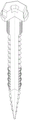
Fig. 1 is a schematic view of the structure of a variety of threaded tapping screws.
Fig. 2 is a three-dimensional structural view of various threaded self-tapping screws.
Fig. 3 is a schematic view of the structure of fig. 2 at a further angle.
Fig. 4 is a quarter sectional view of fig. 3.
Fig. 5 is an enlarged view of a portion a of fig. 2.
In the figure: 1-screw cap, 2-anti-skid ball, 3-mechanical tooth, 4-screw rod, 5-self-tapping tooth, 6-straight tooth row, 7-conical piece, 8-groove and 9-mounting hole.
Detailed Description
The technical solutions in the embodiments of the present invention will be clearly and completely described below with reference to the drawings in the embodiments of the present invention, and it is obvious that the described embodiments are only a part of the embodiments of the present invention, and not all of the embodiments. All other embodiments, which can be derived by a person skilled in the art from the embodiments given herein without making any creative effort, shall fall within the protection scope of the present invention.
In addition, an element of the present invention may be said to be "fixed" or "disposed" to another element, either directly on the other element or with intervening elements present. When an element is referred to as being "connected" to another element, it can be directly connected to the other element or intervening elements may also be present. The terms "vertical," "horizontal," "left," "right," and the like as used herein are for illustrative purposes only and do not represent the only embodiments.
Referring to fig. 1-4, in one embodiment of the present invention, a multi-thread self-tapping screw includes:
a screw shaft 4;
self-tapping 5;
a mechanical tooth 3;
the straight tooth arrangement 6;
wherein the screw cap 1 and the conical piece 7 are respectively arranged at two ends of the screw rod 4, and the self-tapping teeth 5 are spirally distributed on the screw rod 4 and the conical piece 7;
the straight tooth arrangement 6 is circumferentially and equidistantly distributed at the tail end of the screw rod 4, and at least three groups of the straight tooth arrangement 6 are vertically and sequentially arranged;
the screw rod 4 is close to one end of the nut 1 is provided with a mechanical tooth 3, and an inclined plane is arranged between the end face of the mechanical tooth 3 and the screw rod 4.
In the embodiment of the utility model, the nut 1 is screwed by a hexagonal wrench to rotate, the nut 1 drives the screw rod 4 and the conical piece 7 to rotate along with the screw rod, so that the self-tapping teeth 5 and the conical piece 7 are drilled into a plate, the screw rod 4 is driven to gradually enter the plate by the self-tapping teeth 5, and in the process, the straight-row teeth 6 are simultaneously driven to enter the inner side of the plate together, and the straight-row teeth 6 are matched with the inner part of the plate to apply reverse limit to the screw rod 4, so that the screw rod 4 is drilled into the inner side of the plate in a one-way entering manner;
when the screw rod 4 moves to the stroke end, the mechanical teeth 3 are inserted through the inclined surface, the screw thread of the mechanical teeth 3 is used for reinforcing the screw rod and limiting the screw rod again, so that the screw rod 4 cannot be taken out through twice limiting after being turned into the inner side of the plate, and the screw rod 4 is more labor-saving when being screwed into the plate under the clamping of the self-tapping teeth 5;
the screw provided by the utility model can be applied to not only wood plates, but also fiber composite materials and plates made of composite materials;
it should be noted that the length and diameter of the screw shaft 4 and the pitch between the self-tapping teeth 5 in the present invention should be selected according to actual production, and the present application is not limited thereto.
In another embodiment of the present invention, the nut 1 is provided with a hexagonal groove 2, and a PVC anti-slip pad is mounted inside the hexagonal groove 2.
In the embodiment of the utility model, the L-shaped hexagonal wrench can be inserted into the hexagonal groove 2, and the hexagonal wrench is rotated to drive the nut 1 to rotate, which is a very common method;
the PVC anti-slip mat can prevent the hexagonal groove 2 from being damaged due to the rigid connection between the hexagonal wrench and the hexagonal groove 2, namely the PVC anti-slip mat is commonly called as 'slip thread'.
In another embodiment of the present invention, the nut 1, the mechanical teeth 3, the screw rod 4 and the conical member 7 are integrally formed;
the straight tooth arrangement 6 is installed on the screw rod 4 through welding;
wherein, the screw rod 4 is provided with a protruding block which is integrally manufactured with the screw rod at one end facing the screw cap 1, and the mechanical tooth 3 is arranged on the protruding block.
In another embodiment of the present invention, the straight teeth 6 are all provided with a groove 8.
In the embodiment of the utility model, the straight tooth rows 6 are provided with the grooves 8, and the corners of the straight tooth rows are chamfered, so that the plate can be effectively grabbed when the straight tooth rows 6 are limited, the limiting effect is improved, the limiting effect is not influenced even if the grooves 8 are not formed in the straight tooth rows 6, but the effect of forming the grooves 8 is better than that of not forming the grooves, the groove 8 is not specifically limited in the application, and the corresponding adjustment can be carried out according to actual requirements.
In another embodiment of the present invention, the nut 1 includes a hexagonal block and a washer, and the washer is connected to the screw shaft 4.
In the present embodiment, the screw shaft 4 is restrained by a washer as it moves to the end of its travel;
wherein, the hexagonal piece also can set up the recess, the recess is "ten" font or "one" font, and of course other modes can also be adopted, and this application does not specifically limit to this.
In another embodiment of the present invention, the self-tapping screw 5 is provided in segments and uniformly distributed on the screw shaft 4 and outside the conical member 7.
In the present embodiment, the screw shaft 4 and the self-tapping 5 on the conical member 7 are made in one piece, and the self-tapping 5 is cut only at the end of the screw shaft 4 for mounting the straight row of teeth 6.
In another embodiment of the present invention, the protruding blocks are equidistantly provided with mounting holes 9, and the inner sides of the mounting holes 9 are mounted with anti-skid balls made of PVC.
In the embodiment of the utility model, when the screw moves to the stroke end, the anti-skid ball is matched with the thread groove formed in the mechanical tooth 3, so that the situation that the mechanical tooth 3 is matched with the self-tapping groove formed in the self-tapping tooth 5 to generate a skid or non-fit thread can be effectively prevented;
secondly, antiskid ball can prevent to rock because of panel and lead to the unstable condition of this screw installation to take place after this screw installation is accomplished, effectively ensures the stable laminating of this screw after the installation is accomplished.
It will be evident to those skilled in the art that the utility model is not limited to the details of the foregoing illustrative embodiments, and that the present invention may be embodied in other specific forms without departing from the spirit or essential attributes thereof. The present embodiments are therefore to be considered in all respects as illustrative and not restrictive, the scope of the utility model being indicated by the appended claims rather than by the foregoing description, and all changes which come within the meaning and range of equivalency of the claims are therefore intended to be embraced therein. Any reference sign in a claim should not be construed as limiting the claim concerned.
Furthermore, it should be understood that although the present description refers to embodiments, not every embodiment may contain only a single embodiment, and such description is for clarity only, and those skilled in the art should integrate the description, and the embodiments may be combined as appropriate to form other embodiments understood by those skilled in the art.
Claims (6)
1. A multi-thread, self-tapping screw comprising:
a screw shaft (4);
a self-tapping tooth (5);
a mechanical tooth (3);
straight tooth arrangement (6);
a conical member (7);
a nut (1);
the screw cap (1) and the conical piece (7) are respectively arranged at two ends of the screw rod (4), and the self-tapping teeth (5) are spirally distributed on the screw rod (4) and the conical piece (7);
the straight tooth arrangement (6) is equidistantly distributed at the tail end of the screw rod (4) along the circumferential direction, and at least three groups of straight tooth arrangements (6) are equidistantly arranged along the axial direction of the screw rod (4);
the mechanical teeth (3) are arranged at one end, close to the screw cap (1), of the screw rod (4), and inclined planes are arranged between the end face of the mechanical teeth (3) and the screw rod (4).
2. A multi-thread self-tapping screw according to claim 1, wherein said nut (1) is formed with a hexagonal groove (2), and an elastic non-slip mat made of PVC is mounted inside said hexagonal groove (2).
3. A multi-thread self-tapping screw according to claim 1, wherein said nut (1), said mechanical teeth (3), said shank (4), said conical member (7) are made in one piece;
the straight tooth arrangement (6) is welded on the screw rod (4);
wherein, the screw rod (4) is provided with a protruding block which is integrally manufactured with the screw rod towards one end of the screw cap (1), and the mechanical teeth (3) are arranged on the protruding block.
4. A multi-thread self-tapping screw as claimed in claim 1, wherein said straight row of teeth (6) are each provided with a recess (8).
5. A multi-thread self-tapping screw as claimed in claim 1, wherein said nut (1) comprises a hexagonal block and a washer, said washer connecting said screw shank (4).
6. A multi-thread tapping screw as claimed in claim 3, wherein said protruding block is provided with mounting holes (9) at equal intervals, and said mounting holes (9) are internally provided with anti-slip balls made of PVC.
Priority Applications (1)
| Application Number | Priority Date | Filing Date | Title |
|---|---|---|---|
| CN202123127288.3U CN216306434U (en) | 2021-12-13 | 2021-12-13 | Multi-thread self-tapping screw |
Applications Claiming Priority (1)
| Application Number | Priority Date | Filing Date | Title |
|---|---|---|---|
| CN202123127288.3U CN216306434U (en) | 2021-12-13 | 2021-12-13 | Multi-thread self-tapping screw |
Publications (1)
| Publication Number | Publication Date |
|---|---|
| CN216306434U true CN216306434U (en) | 2022-04-15 |
Family
ID=81085213
Family Applications (1)
| Application Number | Title | Priority Date | Filing Date |
|---|---|---|---|
| CN202123127288.3U Active CN216306434U (en) | 2021-12-13 | 2021-12-13 | Multi-thread self-tapping screw |
Country Status (1)
| Country | Link |
|---|---|
| CN (1) | CN216306434U (en) |
-
2021
- 2021-12-13 CN CN202123127288.3U patent/CN216306434U/en active Active
Similar Documents
| Publication | Publication Date | Title |
|---|---|---|
| CN206320154U (en) | A kind of fastener | |
| CN211449343U (en) | Tooth-shaped locknut assembly | |
| CN206682119U (en) | A kind of self-tapping screw | |
| CN216306434U (en) | Multi-thread self-tapping screw | |
| CN208792873U (en) | A kind of semicircle cross-arm anchor ear of electric power laying | |
| CN210660884U (en) | Adjusting bolt | |
| CN112855698A (en) | Anti-loose screw for fixing square pile | |
| CN212407280U (en) | Anti-loosening fastening device for railway contact network | |
| CN209943303U (en) | Self-tapping screw with inverted teeth | |
| CN210068718U (en) | Anti-loosening bolt | |
| CN204082861U (en) | A kind of high ferro contact net to be interlocked locking securing means with special-shaped sour jujube pad | |
| CN211039352U (en) | Fastening type anti-loosening nut | |
| CN210484354U (en) | Anchor nail with self-locking function | |
| CN109253146B (en) | Pressure point type all-metal locking nut | |
| CN214661437U (en) | Anti-loose screw | |
| CN108506309B (en) | Machine screw with convenient screw-off post-treatment | |
| CN208311220U (en) | A kind of coiled hair cross Self Drilling Screws improving degree of being completely embedded | |
| CN209818477U (en) | High-strength segmented self-tapping screw | |
| CN110778589B (en) | Invisible cold heading bolt capable of self-locking | |
| CN214367144U (en) | Novel high-strength anti-loosening fastener | |
| CN214998745U (en) | Locking car screw that moves | |
| CN216278815U (en) | Connecting bolt assembly for elevator car wall | |
| CN212717579U (en) | Hexagonal flange face bolt | |
| CN219953923U (en) | Locking bolt nut subassembly that moves | |
| CN218934988U (en) | Lock nut |
Legal Events
| Date | Code | Title | Description |
|---|---|---|---|
| GR01 | Patent grant | ||
| GR01 | Patent grant |