CN212407280U - Anti-loosening fastening device for railway contact network - Google Patents
Anti-loosening fastening device for railway contact network Download PDFInfo
- Publication number
- CN212407280U CN212407280U CN202021921964.7U CN202021921964U CN212407280U CN 212407280 U CN212407280 U CN 212407280U CN 202021921964 U CN202021921964 U CN 202021921964U CN 212407280 U CN212407280 U CN 212407280U
- Authority
- CN
- China
- Prior art keywords
- nut
- bolt
- main
- contact net
- fastening device
- Prior art date
- Legal status (The legal status is an assumption and is not a legal conclusion. Google has not performed a legal analysis and makes no representation as to the accuracy of the status listed.)
- Active
Links
Images


Landscapes
- Connection Of Plates (AREA)
Abstract
The utility model provides a railway contact net is with locking fastener, including kingbolt, main nut, lock nut, the device further includes: the bolt cutting screws are symmetrically arranged on at least two outer surfaces of the lock catch nut, and the central axis of the bolt cutting screws is perpendicular to the central axis of the main bolt; a tooth pad disposed between the main nut and the latch nut; the oblique direction of the tooth pad is consistent with the rotating direction of the lock nut, and the lock nut, the main nut and the main bolt are respectively consistent with the rotating direction of the installation part; the bolt cutting screw is interlocked with the lock nut and the main bolt respectively, and the tooth pad is interlocked with the main nut and the lock nut.
Description
Technical Field
The utility model relates to a fastener device, in particular to railway is locking fastener for contact net.
Background
The fastening piece used on the electrified contact net of the railway in China still generally adopts the traditional finned gasket or spring washer, the anti-loosening effect is extremely limited, and the fastening piece has great potential safety hazard for railway operation. The fastener used on the electrified contact network of the high-speed railway is mainly introduced into foreign technologies, and a special adhesive is generally coated on the threaded part of a connecting bolt and a connecting nut before the threaded part is installed and screwed, is imported from the United states and Japan, is expensive, and has limited use and storage. The important point is that the use is troublesome, the workpiece is thoroughly cleaned and dried before gluing, and the construction is inconvenient in rainy days, foggy days, sunday days, windy days and frozen days. After construction, the adhesive can not be put into use immediately and can bear the vibration force after the adhesive is solidified thoroughly. Because the height of the wire and the rail is adjusted sometimes in the contact net, the fastener is loosened and tightened. Such glued screws are generally difficult to loosen with a wrench and sometimes must be sawn.
SUMMERY OF THE UTILITY MODEL
To the problem, the utility model aims at providing a combination locking fastener is cut with left-hand thread formula bite-block and tie to electrified contact net of railway, its simple structure, low cost, locking is absolutely reliable, and the installation is dismantled conveniently, can be along with the dress along with using.
In order to solve the technical problem, the utility model provides a railway contact net is with locking fastener, including kingbolt, main nut, lock nut, its characterized in that, the device further includes:
the bolt cutting screws are symmetrically arranged on at least two outer surfaces of the lock catch nut, and the central axis of the bolt cutting screws is perpendicular to the central axis of the main bolt;
a tooth pad disposed between the main nut and the latch nut;
the oblique direction of the tooth pad is consistent with the rotating direction of the lock nut, and the lock nut, the main nut and the main bolt are respectively consistent with the rotating direction of the installation part;
the bolt cutting screw is interlocked with the lock nut and the main bolt respectively, and the tooth pad is interlocked with the main nut and the lock nut.
Preferably, the utility model further discloses an anti-loose fastening device for the railway contact net, which is characterized in that,
the key cutting screw further comprises:
the bolt cutting part is formed by a groove in the end face of the tail part, and an annular cutting edge is formed on the inner wall of the groove and the outer wall of the rod part of the bolt cutting screw.
Preferably, the utility model further discloses an anti-loose fastening device for the railway contact net, which is characterized in that,
the tail further includes a step formed by the outer circumference of the tail of the key cutting screw being smaller than the outer circumference of the shank thereof.
Preferably, the utility model further discloses an anti-loose fastening device for the railway contact net, which is characterized in that,
the inner hollow part is 0.4-0.5 mm higher than the outer diameter of the main bolt thread.
Preferably, the utility model further discloses an anti-loose fastening device for the railway contact net, which is characterized in that,
the bolt cutting screw is inclined inwards from the root diameter thereof by an angle theta 1 ranging from 1 degree to 3 degrees.
Preferably, the utility model further discloses an anti-loose fastening device for the railway contact net, which is characterized in that,
the included angle alpha formed by the inner side and the outer side of the annular cutting edge ranges from 10 degrees to 30 degrees.
Preferably, the utility model further discloses an anti-loose fastening device for the railway contact net, which is characterized in that,
the outer side wall of the annular cutting edge comprises a sawtooth structure.
Preferably, the utility model further discloses an anti-loose fastening device for the railway contact net, which is characterized in that,
the thread diameter and the thread pitch of the main nut and the lock nut are the same, and the rotation directions are opposite.
Preferably, the utility model further discloses an anti-loose fastening device for the railway contact net, which is characterized in that,
the locking nut comprises a hexagonal nut.
Preferably, the utility model further discloses an anti-loose fastening device for the railway contact net, which is characterized in that,
the height of the bolt cutting screw is less than or equal to the depth of the mounting hole of the lock nut.
Compared with the prior art, the utility model has the advantages of it is following:
compare with the locking fastener technique of using on current railway contact net, the beneficial effects of the utility model reside in that, the utility model discloses simple structure, low cost, locking is reliable, and the installation is dismantled conveniently. The device is used in a railway electrification contact network, can realize all-weather operation, and greatly improves the economic benefit of railway operation.
Drawings
The accompanying drawings, which are included to provide a further understanding of the application and are incorporated in and constitute a part of this application, illustrate embodiment(s) of the application and together with the description serve to explain the principle of the invention. In the drawings:
fig. 1(1) is a schematic view of the anti-loose fastening device for the railway contact net;
FIG. 1(2) is a sectional view taken along line A-A in FIG. 1 (1);
FIG. 2 is a cross-sectional view of the bolt-cutting screw 15 of FIG. 1 (1);
FIG. 3(1) is a front view of the tooth pad 13 in FIG. 1 (1);
FIG. 3(2) is a sectional view A-A of FIG. 3 (1);
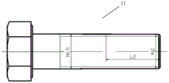
fig. 4 is a schematic structural view of the main bolt 11 in fig. 1 (1).
Reference numerals
11-main bolt
12-main nut
13-tooth pad
14-locking nut
15-bolt cutting screw
151-head
1511-mounting hole
152-tail part
153-hollow portion
1531-inner wall
1532-outer wall
154-annular cutting edge
155-bolt cutting part
158-rod part
Detailed Description
In order to more clearly illustrate the technical solutions of the embodiments of the present application, the drawings used in the description of the embodiments will be briefly introduced below. It is obvious that the drawings in the following description are only examples or embodiments of the application, from which the application can also be applied to other similar scenarios without inventive effort for a person skilled in the art. Unless otherwise apparent from the context, or otherwise indicated, like reference numbers in the figures refer to the same structure or operation.
As used in this application and the appended claims, the terms "a," "an," "the," and/or "the" are not intended to be inclusive in the singular, but rather are intended to be inclusive in the plural unless the context clearly dictates otherwise. In general, the terms "comprises" and "comprising" merely indicate that steps and elements are included which are explicitly identified, that the steps and elements do not form an exclusive list, and that a method or apparatus may include other steps or elements.
The relative arrangement of the components and steps, the numerical expressions, and numerical values set forth in these embodiments do not limit the scope of the present application unless specifically stated otherwise. Meanwhile, it should be understood that the sizes of the respective portions shown in the drawings are not drawn in an actual proportional relationship for the convenience of description. Techniques, methods, and apparatus known to those of ordinary skill in the relevant art may not be discussed in detail but are intended to be part of the specification where appropriate. In all examples shown and discussed herein, any particular value should be construed as merely illustrative, and not limiting. Thus, other examples of the exemplary embodiments may have different values. It should be noted that: like reference numbers and letters refer to like items in the following figures, and thus, once an item is defined in one figure, further discussion thereof is not required in subsequent figures.
In the description of the present application, it is to be understood that the orientation or positional relationship indicated by the directional terms such as "front, rear, upper, lower, left, right", "lateral, vertical, horizontal" and "top, bottom", etc., are generally based on the orientation or positional relationship shown in the drawings, and are used for convenience of description and simplicity of description only, and in the case of not making a reverse description, these directional terms do not indicate and imply that the device or element being referred to must have a particular orientation or be constructed and operated in a particular orientation, and therefore, should not be considered as limiting the scope of the present application; the terms "inner and outer" refer to the inner and outer relative to the profile of the respective component itself.
Spatially relative terms, such as "above … …," "above … …," "above … …," "above," and the like, may be used herein for ease of description to describe one device or feature's spatial relationship to another device or feature as illustrated in the figures. It will be understood that the spatially relative terms are intended to encompass different orientations of the device in use or operation in addition to the orientation depicted in the figures. For example, if a device in the figures is turned over, devices described as "above" or "on" other devices or configurations would then be oriented "below" or "under" the other devices or configurations. Thus, the exemplary term "above … …" can include both an orientation of "above … …" and "below … …". The device may be otherwise variously oriented (rotated 90 degrees or at other orientations) and the spatially relative descriptors used herein interpreted accordingly.
It should be noted that the terms "first", "second", and the like are used to define the components, and are only used for convenience of distinguishing the corresponding components, and the terms have no special meanings unless otherwise stated, and therefore, the scope of protection of the present application is not to be construed as being limited. Further, although the terms used in the present application are selected from publicly known and used terms, some of the terms mentioned in the specification of the present application may be selected by the applicant at his or her discretion, the detailed meanings of which are described in relevant parts of the description herein. Further, it is required that the present application is understood not only by the actual terms used but also by the meaning of each term lying within.
Fig. 1(1) shows a schematic view of the anti-loose fastening device for railway catenary.
The device comprises a main bolt 11, a main nut 12, a toothed pad 13, a lock nut 14 and a bolt-cutting screw 15, the main nut 12 and the lock nut 14 of the embodiment shown in the figures are both hexagonal nuts, but the bolt-cutting screw is only schematically located on one of the hexagonal surfaces of the lock nut 14, and the other bolt-cutting screw is located at the position of the hexagonal surface of symmetry of the lock nut 14.
The main nut 12 and the lock nut 14 have the same thread diameter and thread pitch, and have opposite rotation directions.
Fig. 1(2) further illustrates a cross-sectional view a-a of fig. 1(1), showing the location of the key cutting screw 15, as described in detail in connection with fig. 2.
Fig. 2 shows a cross-sectional view of the key cutting screw 15 shown in fig. 1 (2).
The key cut screw 15 includes a head 151, a tail 152 and a shaft 158, and the tail 152 is in contact with the main bolt 11 to form a key cut 155.
In fig. 2, a groove is formed along the axial line on the end surface of the tail portion 152 to form an inner hollow portion 153, the inner hollow portion 153 is shown in a sectional view in a flared shape with a wide outer side and a narrow inner side, the sectional view in the preferred embodiment is shown as an isosceles trapezoid, and an inner wall 1531 of the inner hollow portion 153 and an outer wall 1532 of the shaft portion of the cutting screw 15 form an annular cutting edge 154.
To achieve a better cutting edge effect, the outer circumference of the tail portion 152 of the key cutting screw 15 is smaller at the key cutting portion 155 than at the shank portion 158, so that a step 1581 is formed at the transition of the shank portion 158 to the tail portion 152, corresponding to the difference in diameter between the head portion 151 and the tail portion 152 of the key cutting screw 15 in the figure, i.e., (M-d).
As shown in fig. 1(1), the cutting screw 15 is inclined inward at an angle θ 1 of 1 to 3 degrees from its root diameter, and d is naturally slightly smaller than the root diameter. When the material is better, intensity is high, gets the low angle, and the blade is sharper (sharper).
The edge of the annular cutting edge 154 is to be cut to the thread of the main bolt 11, and the edge is cut to the root diameter of the main bolt 11.
As shown in FIG. 2, the included angle α formed by the inside and outside of the annular cutting edge 154 is between 10 degrees and 30 degrees, and is smaller when the material is good.
The inner hollow part 153 of the annular cutting edge 154 is 0.4 mm-0.5 mm higher than the outer diameter of the main bolt thread, which aims to facilitate the cutting edge undercut, and the bottom edge of the inner hollow part 153 is 0.4 mm-0.5 mm higher than the outer diameter of the main bolt 11, which means that the upper bottom of the inner hollow part 153 and the outer diameter of the main bolt 11 have a gap a of 0.4 mm-0.5 mm, which does not obstruct the cutting edge undercut.
The above-described structure is a characteristic of this embodiment, and if the gap a is not provided, the upper bottom of the hollow portion 153 will hit the thread portion of the main bolt 11 having the outer diameter or less, and not only the cutting edge will be cut, but also the upper bottom of the hollow portion 153 will hit the thread portion of the main bolt 11 to break the thread, which will disturb smooth removal of the nut from the main bolt 11 in the future.
In addition, in the illustrated embodiment, the head 151 has a linear slot as a mounting hole 1511 for inserting a driver to screw the bolt-cutting screw 15 during mounting.
The height H of the bolt-cutting screw 15 with the structure is less than or equal to the depth of the mounting hole in the lock nut 14, so that the rear end of the bolt-cutting screw is flush with the hexagonal plane of the lock nut 14 after the bolt-cutting screw is mounted, the appearance of the lock nut is kept complete, and the effect of attractive appearance of the device is achieved.
The bolt cutting screw 15 of the utility model is a cross bolt screw which is made of hardened steel and is screwed on the lock catch nut 14. Typically only two are used, in a symmetrical arrangement in the middle of the locking nut 14.
In the preferred embodiment, the annular edge at the bottom of the bolt cutting screw 15 is a full circle continuous edge structure, and may also be serrated, and although the "bolt cutting" effect of the serrated edge is inferior to that of the continuous edge, the serrated edge is easier to cut into the threaded portion of the main bolt when the screw is tightened.
Fig. 3(1) and 3(2) are further views showing the structure and a partial enlarged view of the tooth pad 13 in fig. 1.
The tooth shape of the tooth pad 13 in this embodiment adopts a right-oblique shape. The right angle is intended to cooperate with a right handed locking nut 14. When the clinch nut 14 is tightened right, the end surfaces slide over the tooth surfaces without interfering with the tightening of the nut 14.
When the nut 14 is loosened in the reverse direction (left direction), the tips of the teeth abut against the end surface of the nut, see the sectional view a-a shown in fig. 3(2), thereby preventing the nut from being loosened.
The dimensions of the parts of the toothed pad 13 only affect the anti-loosening effect, but do not change the basic characteristics. Ratchet pads, serrated pads … …, etc. all have this basic characteristic.
The tooth pad is punched to ensure that the tooth tip is sharp, and the work is loose-proof and reliable after quenching and hardening. The locking nut is made of martensitic stainless steel, so that the mechanism can be prevented from loosening more effectively.
Fig. 4 shows a schematic structural view of the main bolt 11.
The L2 section of the locking section of the main bolt 11 is provided with a positive right thread on the basis of the original M1 reverse left thread, and the outer diameter and the thread pitch of the right thread are the same as those of the main nut 12. The L2 section of the main bolt 11 can thus be passed through both the left-hand main nut 12 and the right-hand locking nut 14.
With the above structure, please refer to fig. 1(1), which further illustrates the assembly process of the present invention.
When the main bolt 11 is inserted into the connected member, the main nut 12 is tightened to complete the connection, the tooth pad 13 is mounted and the locking nut 14 is tightened, and then the bolt-cutting screw 15 is screwed into the locking nut 14 so that the annular cutting edge 154 at the front end of the screw is cut to the root of the thread of the main bolt 11.
A tooth pad 13 is arranged between the main nut 11 and the lock nut 14, the tooth shape of the tooth pad 13 is right-inclined, and when the lock nut 14 is screwed rightwards, the tooth pad 13 does not influence locking. However, when the lock nut 14 is unscrewed to the left, the tips of the teeth of the tooth pads 13 abut against the end of the lock nut 14 to prevent it from loosening.
The mechanism adopts a design of interlocking of positive and negative threads, namely, after the main nut 12 is screwed down reversely, the lock nut 14 is screwed down forwardly. Due to the orientation of the teeth of the tooth pad 13, when the locknut 14 is tightened, the teeth tip only back forward, not acting on the main nut 12, to tighten the locknut 14 to a prescribed torque. When the mechanism is likely to loosen due to vibration in the working state, the main nut 11 has a positive right-handed tendency, and the teeth tips on the tooth pads 13 just abut against the end surface of the main nut 11, and the main nut 11 forces the lock nut 14 to turn right together with the lock nut 11, but the lock nut 14 is already screwed right, so that the lock nut 14 is screwed more tightly by the "forcing" of the main nut 11, and the loosening of the main nut 11 is impossible.
When the position in the lock nut 14 reaches the upper edge in the external thread of the main bolt 11, two bolt-cutting bolts 15 are generally used.
The outer side of the annular cutting edge 154 extends from the thread inner diameter at the front end of the screw section to the thread root diameter of all main bolts which can be cut by the annular cutting edge in a downward mode at a small angle of 1-3 degrees of vertical or inward inclination.
The design of the annular cutting edge 154 is that only a small micro-opening is cut on the main bolt 11, the thread integrity of the main bolt 11 is not damaged, and the light rotation of the main and lock nuts during disassembly is convenient. The bolt cutting screw 15 further secures the locknut 14 to the main bolt 11, which is a double anti-loosening measure to ensure the absolute reliability of the high-speed rail operation. The bolt-cutting screw 15 is a small part, although the structure is complex and the technological content is high, when the automatic tooling equipment is used for mass production, the manufacturing cost is low, the bolt-cutting screw can be used as an easily-consumed product and can be scrapped once, but the bolt-cutting screw is certainly significant in ensuring the safety.
The bolt cutting screw 15 is used for firmly bolting the lock nut 14 and the main bolt 11 together like a bolt, and is small, exquisite, complex, fine in manufacturing, high in material requirement, high in toughness and high in hardness after quenching and tempering. The annular cutting edge 154 at the front end is sharp and sharp to facilitate penetration of the main bolt 11.
The utility model discloses a device during operation, the king bolt is bearing operating stress with the main nut, is the main atress spare. The tooth pad, the lock nut and the bolt cutting screw are only used for preventing looseness, do not directly bear working stress, and play a role of 'locking' for preventing looseness although the stress on the tooth pad is not large.
The ' checkpoint ' is vital and is absolutely not necessary, if the checkpoint ' does not exist, ordinary bolt and nut connection is formed, and when the contact net shakes and shakes, the ordinary connection is easy to loosen, so that the contact net steps and collapses, and terrible accidents are caused.
It should be noted that although the locknut does not need to bear the main working stress, namely the clamping force, during actual installation, as the locknut is tightly attached to the main nut through the tooth pad, the specified torque requirement is provided for the locknut, and after the locknut is tightened according to the specification, the locknut also generates a considerable pulling force for the main bolt, and the pulling force is consistent with the clamping force in the direction, namely, the locknut also generates an additional clamping force for a clamped object objectively, so that the connection reliability of the device is increased.
To sum up, the utility model discloses a device is a novel design, and its principle is clean skin, novel structure, thinks about miraculous, and the overall arrangement is simple, low in cost, convenient to use, reliable operation. The method not only contains the advantages and essences of various previous thread anti-loosening methods, but also has unique innovation points. The anti-loosening fastener is used as an anti-loosening fastener on a railway contact net, can ensure all-weather safe operation, and is an ideal optional scheme.
Having thus described the basic concept, it will be apparent to those skilled in the art that the foregoing disclosure is by way of example only, and is not intended to limit the present application. Various modifications, improvements and adaptations to the present application may occur to those skilled in the art, although not explicitly described herein. Such modifications, improvements and adaptations are proposed in the present application and thus fall within the spirit and scope of the exemplary embodiments of the present application.
Also, this application uses specific language to describe embodiments of the application. Reference throughout this specification to "one embodiment," "an embodiment," and/or "some embodiments" means that a particular feature, structure, or characteristic described in connection with at least one embodiment of the present application is included in at least one embodiment of the present application. Therefore, it is emphasized and should be appreciated that two or more references to "an embodiment" or "one embodiment" or "an alternative embodiment" in various places throughout this specification are not necessarily all referring to the same embodiment. Furthermore, some features, structures, or characteristics of one or more embodiments of the present application may be combined as appropriate.
Similarly, it should be noted that in the preceding description of embodiments of the present application, various features are sometimes grouped together in a single embodiment, figure, or description thereof for the purpose of streamlining the disclosure and aiding in the understanding of one or more of the embodiments. This method of disclosure, however, is not intended to require more features than are expressly recited in the claims. Indeed, the embodiments may be characterized as having less than all of the features of a single embodiment disclosed above.
Numerals describing the number of components, attributes, etc. are used in some embodiments, it being understood that such numerals used in the description of the embodiments are modified in some instances by the use of the modifier "about", "approximately" or "substantially". Unless otherwise indicated, "about", "approximately" or "substantially" indicates that the number allows a variation of ± 20%. Accordingly, in some embodiments, the numerical parameters used in the specification and claims are approximations that may vary depending upon the desired properties of the individual embodiments. In some embodiments, the numerical parameter should take into account the specified significant digits and employ a general digit preserving approach. Notwithstanding that the numerical ranges and parameters setting forth the broad scope of the range are approximations, in the specific examples, such numerical values are set forth as precisely as possible within the scope of the application.
Although the present application has been described with reference to the present specific embodiments, it will be recognized by those skilled in the art that the foregoing embodiments are merely illustrative of the present application and that various changes and substitutions of equivalents may be made without departing from the spirit of the application, and therefore, it is intended that all changes and modifications to the above-described embodiments that come within the spirit of the application fall within the scope of the claims of the application.
Claims (10)
1. The utility model provides a railway is locking fastener for contact net, includes king bolt, main nut, lock nut, its characterized in that, the device further includes:
the bolt cutting screws are symmetrically arranged on at least two outer surfaces of the lock catch nut, and the central axis of the bolt cutting screws is perpendicular to the central axis of the main bolt;
a tooth pad disposed between the main nut and the latch nut;
the oblique direction of the tooth pad is consistent with the rotating direction of the lock nut, and the lock nut, the main nut and the main bolt are respectively consistent with the rotating direction of the installation part;
the bolt cutting screw is interlocked with the lock nut and the main bolt respectively, and the tooth pad is interlocked with the main nut and the lock nut.
2. The anti-loose fastening device for the railway contact net according to claim 1, characterized in that,
the key cutting screw further comprises:
the bolt cutting part is formed by a groove in the end face of the tail part, and an annular cutting edge is formed on the inner wall of the groove and the outer wall of the rod part of the bolt cutting screw.
3. The anti-loose fastening device for the railway contact net according to claim 2, characterized in that,
the tail further includes a step formed by the outer circumference of the tail of the key cutting screw being smaller than the outer circumference of the shank thereof.
4. The anti-loose fastening device for the railway contact net according to claim 3, characterized in that,
the inner hollow part is 0.4-0.5 mm higher than the outer diameter of the main bolt thread.
5. The anti-loose fastening device for the railway contact net according to claim 4, characterized in that,
the bolt cutting screw is inclined inwards from the root diameter thereof by an angle theta 1 ranging from 1 degree to 3 degrees.
6. The anti-loose fastening device for the railway contact net according to claim 5, characterized in that,
the included angle alpha formed by the inner side and the outer side of the annular cutting edge ranges from 10 degrees to 30 degrees.
7. The anti-loose fastening device for the railway contact net according to claim 6, characterized in that,
the outer side wall of the annular cutting edge comprises a sawtooth structure.
8. The anti-loose fastening device for the railway contact net according to claim 7, characterized in that,
the thread diameter and the thread pitch of the main nut and the lock nut are the same, and the rotation directions are opposite.
9. The anti-loose fastening device for the railway contact net according to claim 8, characterized in that,
the locking nut comprises a hexagonal nut.
10. The anti-loose fastening device for the railway contact net according to claim 9, characterized in that,
the height of the bolt cutting screw is less than or equal to the depth of the mounting hole of the lock nut.
Priority Applications (1)
| Application Number | Priority Date | Filing Date | Title |
|---|---|---|---|
| CN202021921964.7U CN212407280U (en) | 2020-09-04 | 2020-09-04 | Anti-loosening fastening device for railway contact network |
Applications Claiming Priority (1)
| Application Number | Priority Date | Filing Date | Title |
|---|---|---|---|
| CN202021921964.7U CN212407280U (en) | 2020-09-04 | 2020-09-04 | Anti-loosening fastening device for railway contact network |
Publications (1)
| Publication Number | Publication Date |
|---|---|
| CN212407280U true CN212407280U (en) | 2021-01-26 |
Family
ID=74374217
Family Applications (1)
| Application Number | Title | Priority Date | Filing Date |
|---|---|---|---|
| CN202021921964.7U Active CN212407280U (en) | 2020-09-04 | 2020-09-04 | Anti-loosening fastening device for railway contact network |
Country Status (1)
| Country | Link |
|---|---|
| CN (1) | CN212407280U (en) |
-
2020
- 2020-09-04 CN CN202021921964.7U patent/CN212407280U/en active Active
Similar Documents
| Publication | Publication Date | Title |
|---|---|---|
| CN108533601A (en) | A kind of self-locking screw | |
| DE102014018280A1 (en) | Fastening device for fastening a rotor blade to a rotor hub of a wind turbine | |
| CN212407280U (en) | Anti-loosening fastening device for railway contact network | |
| CN208686782U (en) | A kind of self-locking screw | |
| CN104454914A (en) | Plough type ratchet pad lock catch anti-loose device for railway touching net | |
| CN114135562A (en) | Anti-loosening fastening device for railway contact network | |
| CN203835922U (en) | Reversely-buckled type self-locking anti-loose fastener for high-speed rail electrified catenary | |
| CN108386440A (en) | Locking Anti-off bolt nut assembly | |
| CN202790003U (en) | Anti-rotating locknut | |
| CN204344652U (en) | A kind of railway contact line plough sour jujube pad snap close locking device | |
| JP2007271032A (en) | Bolt joint structure | |
| US2601385A (en) | Screw stud | |
| CN204082861U (en) | A kind of high ferro contact net to be interlocked locking securing means with special-shaped sour jujube pad | |
| CN213235766U (en) | Locking fastening assembly that moves with bearing structure | |
| CN2126344U (en) | Shockproof anti-releasing screw fastener | |
| CN219953923U (en) | Locking bolt nut subassembly that moves | |
| CN214998745U (en) | Locking car screw that moves | |
| DE20218799U1 (en) | Radschraube | |
| CN2769594Y (en) | Ratchet antitheft bolt and clamping tool | |
| DE2306087A1 (en) | SCREW ELEMENT SUCH AS HEAD SCREW OR MOTHER | |
| CN220415966U (en) | Screw, nut and bolt assembly | |
| CN213839210U (en) | Bolt fastener with locking structure | |
| CN214404279U (en) | Anti-theft bolt | |
| CN110630616A (en) | Bolt nut piece capable of never loosening | |
| WO2013180239A1 (en) | Self-tapping screw and attachment structure thereof |
Legal Events
| Date | Code | Title | Description |
|---|---|---|---|
| GR01 | Patent grant | ||
| GR01 | Patent grant |