CN216265637U - Steel construction processing accurate positioning clamping device - Google Patents
Steel construction processing accurate positioning clamping device Download PDFInfo
- Publication number
- CN216265637U CN216265637U CN202123058106.1U CN202123058106U CN216265637U CN 216265637 U CN216265637 U CN 216265637U CN 202123058106 U CN202123058106 U CN 202123058106U CN 216265637 U CN216265637 U CN 216265637U
- Authority
- CN
- China
- Prior art keywords
- base
- rod
- screw
- accurate positioning
- clamping device
- Prior art date
- Legal status (The legal status is an assumption and is not a legal conclusion. Google has not performed a legal analysis and makes no representation as to the accuracy of the status listed.)
- Active
Links
Images


Abstract
The utility model belongs to the technical field of clamps and discloses an accurate positioning and clamping device for steel structure machining, which comprises a base, wherein a thread groove is formed in the top of the base, a screw tube is connected to the inside of the thread groove in a screwing mode, a connecting rod is installed inside the screw tube, a base rod is fixedly connected to the top of the connecting rod, a lead screw is connected to the inside of the base rod in a screwing mode, a clamping plate is installed at one end of the lead screw, a rotating head is installed at the other side of the lead screw, and an adjusting screw is connected to one side of the screw tube in a screwing mode. The screw pipes, the connecting rods and the base rods are fixed at the positions required by a user through the screwing connection of the screw pipes and the thread grooves, the rotating head is rotated, the screw rod moves in the base rod, the clamping plates abut against the workpiece, and when the device fixes the workpiece, irregular workpieces can be fixed, the device can be used in different use environments, and the use range of the device is enlarged.
Description
Technical Field
The utility model belongs to the technical field of clamps, and particularly relates to a steel structure machining accurate positioning and clamping device.
Background
The jig is a device for fixing a workpiece to be machined to a correct position for construction or inspection in a machine manufacturing process, and may be called a jig, and in a broad sense, in any process in a process, a device for quickly, conveniently and safely installing a workpiece may be called a jig, and the jig generally includes a positioning element (for determining a correct position of the workpiece in the jig), a clamping device, a tool setting guide element (for determining a relative position between a tool and the workpiece or guiding a tool direction), an indexing device (for enabling the workpiece to be machined at a plurality of stations in one installation, including a rotary indexing device and a linear movement indexing device), a connecting element, a jig body (a jig base), and the like.
When the workpiece is fixed by the existing steel structure machining accurate positioning and clamping device, regular workpieces can only be fixed, irregular workpieces cannot be fixed, the device can only be used for fixing the use environment, and the use range of the device has limitation.
SUMMERY OF THE UTILITY MODEL
The utility model aims to provide an accurate positioning and clamping device for steel structure machining, which aims to solve the problems that irregular workpieces cannot be fixed and the application range of the device is limited in the background technology.
In order to achieve the purpose, the utility model provides the following technical scheme: the utility model provides a steel construction processing accurate positioning clamping device, includes the base, the thread groove has been seted up at the top of base, the inside of thread groove closes soon and is connected with the screwed pipe, the internally mounted of screwed pipe has the connecting rod, the top fixedly connected with base rod of connecting rod, the inside of base rod closes soon and is connected with the lead screw, splint are installed to the one end of lead screw, and the opposite side is installed and is turned round.
Preferably, one side of the screw pipe is connected with an adjusting screw rod in a screwing mode, and side rods are arranged on two sides of the circumferential surface of the adjusting screw rod.
Preferably, a rubber pad is arranged on one side, back to the screw rod, of the clamping plate.
Preferably, the rotating head is provided with an annular groove.
Preferably, the bottom of the base is provided with a support rod, and the bottom of the support rod is provided with a bottom foot.
Preferably, one side of the connecting rod, which is close to the adjusting screw rod, is provided with a limiting groove.
Compared with the prior art, the utility model has the beneficial effects that:
(1) the screw pipes, the connecting rods and the base rods are fixed at the positions required by a user through the screwing connection of the screw pipes and the thread grooves, the rotating head is rotated, the screw rod moves in the base rod, the clamping plates abut against the workpiece, and when the device fixes the workpiece, irregular workpieces can be fixed, the device can be used in different use environments, and the use range of the device is enlarged.
(2) On the basis of the beneficial effects, the base rod is pulled to drive the connecting rod to move in the screw tube, the adjusting screw rod is screwed after the connecting rod and the base rod move to the position required by a user, and the connecting rod and the base rod are fixed at the position required by the user, so that the device is convenient to adjust according to a workpiece, and the application range of the device is further enlarged.
Drawings
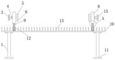
FIG. 1 is a schematic structural view of the present invention;
FIG. 2 is an internal structural view of the present invention;
FIG. 3 is an enlarged view of portion A of FIG. 2;
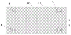
FIG. 4 is a top view of the present invention;
FIG. 5 is a top plan view of the present invention in use;
in the figure: 1. a support bar; 2. a side lever; 3. turning the head; 4. a screw rod; 5. a splint; 6. a rubber pad; 7. adjusting the screw rod; 8. a base shaft; 9. a connecting rod; 10. a base; 11. footing; 12. a solenoid; 13. a thread groove; 14. a limiting groove; 15. an annular groove.
Detailed Description
The technical solutions in the embodiments of the present invention will be clearly and completely described below with reference to the drawings in the embodiments of the present invention, and it is obvious that the described embodiments are only a part of the embodiments of the present invention, and not all of the embodiments. All other embodiments, which can be derived by a person skilled in the art from the embodiments given herein without making any creative effort, shall fall within the protection scope of the present invention.
Referring to fig. 1-5, the present invention provides the following technical solutions: the utility model provides a steel construction processing accurate positioning clamping device, which comprises a base 10, thread groove 13 has been seted up at the top of base 10, thread groove 13's inside closes soon and is connected with screwed pipe 12, the internally mounted of screwed pipe 12 has connecting rod 9, the top fixedly connected with base rod 8 of connecting rod 9, the inside of base rod 8 closes soon and is connected with lead screw 4, splint 5 are installed to the one end of lead screw 4, the opposite side is installed and is turned round 3, close screwed pipe 12 and the thread groove 13 on the base 10 soon and be connected, make screwed pipe 12, connecting rod 9 and base rod 8 are fixed in the position department that the user needs, it turns round 3 to rotate, thereby drive lead screw 4 and rotate, make lead screw 4 remove in base rod 8, drive splint 5 through lead screw 4 and remove, support the work piece through splint 5.
Furthermore, one side of the screw tube 12 is connected with an adjusting screw rod 7 in a screwing mode, side rods 2 are installed on two sides of the circumferential surface of the adjusting screw rod 7, the connecting rod 9 is pulled to enable the connecting rod 9 to move in the screw tube 12, and after the connecting rod 9 and the base rod 8 move to the position required by a user, the adjusting screw rod 7 is screwed down to enable the connecting rod 9 to be fixed to the position required by the user on the screw tube 12.
Furthermore, a rubber pad 6 is arranged on one side, back to the screw rod 4, of the clamping plate 5, and the clamping plate 5 is fastened to the workpiece through the rubber pad 6.
Furthermore, an annular groove 15 is formed in the rotor 3, and the rotor 3 is convenient to rotate through the annular groove 15.
Further, the bracing piece 1 is installed to base 10 bottom, and footing 11 is installed to 1 bottom of bracing piece, supports base 10 through footing 11 and bracing piece 1, lets base 10 place the back more firm.
Furthermore, a limiting groove 14 is formed in one side, close to the adjusting screw 7, of the connecting rod 9, and the adjusting screw 7 is more tightly pressed against the connecting rod 9 through the limiting groove 14.
The working principle and the using process of the utility model are as follows: when the utility model is used, the base 10 is supported by the support rod 1 and the footing 11, after the base 10 is stabilized, the screwed pipe 12 and the thread groove 13 are screwed and connected, the screwed pipe 12, the connecting rod 9 and the base rod 8 with the required number are fixed on the base 10 at the position required by the user, the workpiece to be fixed is placed on the base 10, the base rod 8 is pulled to move the base rod 8 in the screwed pipe 12, after the base rod 8 and the connecting rod 9 are moved to the position required by the user, the adjusting screw rod 7 is rotated by the side lever 2 to support the connecting rod 9, the connecting rod 9 and the base rod 8 are fixed at the position required by the user, the screw rod 4 is rotated by the rotating head 3, the screw rod 4 is moved in the base rod 8, the clamp plate 5 is driven to move by the screw rod 4, the clamp plate 5 supports the workpiece, and under the action of the rubber pad 6, the workpiece is more fastened after being fixed, after the workpiece is fixed, the user can conveniently process the workpiece.
It is noted that, herein, relational terms such as first and second, and the like may be used solely to distinguish one entity or action from another entity or action without necessarily requiring or implying any actual such relationship or order between such entities or actions. Also, the terms "comprises," "comprising," or any other variation thereof, are intended to cover a non-exclusive inclusion, such that a process, method, article, or apparatus that comprises a list of elements does not include only those elements but may include other elements not expressly listed or inherent to such process, method, article, or apparatus.
Although embodiments of the present invention have been shown and described, it will be appreciated by those skilled in the art that changes, modifications, substitutions and alterations can be made in these embodiments without departing from the principles and spirit of the utility model, the scope of which is defined in the appended claims and their equivalents.
Claims (6)
1. The utility model provides a steel construction processing accurate positioning clamping device which characterized in that: including base (10), thread groove (13) have been seted up at the top of base (10), the inside of thread groove (13) closes soon and is connected with solenoid (12), the internally mounted of solenoid (12) has connecting rod (9), top fixedly connected with base rod (8) of connecting rod (9), the inside of base rod (8) closes soon and is connected with lead screw (4), splint (5) are installed to the one end of lead screw (4), and the opposite side is installed and is turned round (3).
2. The steel structure machining accurate positioning and clamping device of claim 1, characterized in that: one side of the solenoid (12) is connected with an adjusting screw (7) in a screwing mode, and side rods (2) are installed on two sides of the circumferential surface of the adjusting screw (7).
3. The steel structure machining accurate positioning and clamping device of claim 2, characterized in that: and a rubber pad (6) is arranged on one side of the clamping plate (5) back to the screw rod (4).
4. The steel structure machining accurate positioning and clamping device of claim 3, wherein: the rotary head (3) is provided with an annular groove (15).
5. The steel structure machining accurate positioning and clamping device of claim 4, wherein: the support rod (1) is installed to base (10) bottom, footing (11) are installed to bracing piece (1) bottom.
6. The steel structure machining accurate positioning and clamping device of claim 5, wherein: and a limiting groove (14) is formed in one side, close to the adjusting screw rod (7), of the connecting rod (9).
Priority Applications (1)
| Application Number | Priority Date | Filing Date | Title |
|---|---|---|---|
| CN202123058106.1U CN216265637U (en) | 2021-12-08 | 2021-12-08 | Steel construction processing accurate positioning clamping device |
Applications Claiming Priority (1)
| Application Number | Priority Date | Filing Date | Title |
|---|---|---|---|
| CN202123058106.1U CN216265637U (en) | 2021-12-08 | 2021-12-08 | Steel construction processing accurate positioning clamping device |
Publications (1)
| Publication Number | Publication Date |
|---|---|
| CN216265637U true CN216265637U (en) | 2022-04-12 |
Family
ID=81042646
Family Applications (1)
| Application Number | Title | Priority Date | Filing Date |
|---|---|---|---|
| CN202123058106.1U Active CN216265637U (en) | 2021-12-08 | 2021-12-08 | Steel construction processing accurate positioning clamping device |
Country Status (1)
| Country | Link |
|---|---|
| CN (1) | CN216265637U (en) |
-
2021
- 2021-12-08 CN CN202123058106.1U patent/CN216265637U/en active Active
Similar Documents
| Publication | Publication Date | Title |
|---|---|---|
| CN208895636U (en) | Novel clamp is used in a kind of machining | |
| CN216265637U (en) | Steel construction processing accurate positioning clamping device | |
| CN211414416U (en) | Brake block adds clamping apparatus with adjust not unidimensional | |
| CN219521702U (en) | Automatic steel pipe polishing machine | |
| CN216327823U (en) | A fixed tool for tubular metal resonator detects | |
| CN102049697B (en) | Fixture for processing small-bore bending machines | |
| CN218135042U (en) | Aluminum cylinder numerical control machining internal stay clamp | |
| CN217290946U (en) | Clamp for laser cutting | |
| CN212886002U (en) | Welding assembly line fixture with rapid positioning and locking functions | |
| CN208841046U (en) | A kind of fixture for pivoting support polar coordinates drilling machine | |
| CN213258198U (en) | Machining clamp for workpiece with taper hole on numerical control machine tool | |
| CN214244536U (en) | Clamp for heat treatment of mechanical workpiece | |
| CN210649554U (en) | Novel anchor clamps for machine-building | |
| CN201863035U (en) | Mechanical processing clamp for minor-caliber bend | |
| CN212146036U (en) | Precision positioning clamp | |
| CN211761036U (en) | Screw rod stress application bench clamp with movable station | |
| CN217019513U (en) | Auxiliary clamping component of numerical control machine tool | |
| CN219521261U (en) | Connecting block adds clamping apparatus | |
| CN206140155U (en) | A location fixture device for CNC clamping work piece | |
| CN210189065U (en) | Numerical control end face machining machine tool fixture | |
| CN219094411U (en) | Automatic centering fixture for conical workpiece | |
| CN215616613U (en) | Large-diameter clamp for machining pipe fitting | |
| CN211939897U (en) | Chamfering machine machining clamp | |
| CN214445717U (en) | Panel terminal surface anchor clamps convenient to adjustment fixed position | |
| CN219152658U (en) | Can prevent mounting fixture of damage |
Legal Events
| Date | Code | Title | Description |
|---|---|---|---|
| GR01 | Patent grant | ||
| GR01 | Patent grant |