CN216265391U - Accurate angle processing auxiliary device of grinding machine - Google Patents
Accurate angle processing auxiliary device of grinding machine Download PDFInfo
- Publication number
- CN216265391U CN216265391U CN202122986582.3U CN202122986582U CN216265391U CN 216265391 U CN216265391 U CN 216265391U CN 202122986582 U CN202122986582 U CN 202122986582U CN 216265391 U CN216265391 U CN 216265391U
- Authority
- CN
- China
- Prior art keywords
- inclined plane
- angle
- auxiliary device
- grinding machine
- block
- Prior art date
- Legal status (The legal status is an assumption and is not a legal conclusion. Google has not performed a legal analysis and makes no representation as to the accuracy of the status listed.)
- Active
Links
Images


Abstract
The utility model belongs to the technical field of machining of grinding machines, and particularly relates to a precise angle machining auxiliary device of a grinding machine, which comprises a fixed base, a grinding wheel and workpieces, wherein an angle block is fixedly arranged on one side of the top of the fixed base, a rotating base is also arranged at the upper end of the fixed base, an angle adjusting effect is achieved by arranging a stepped angle block to be matched with a support column, when the support column is placed on the same step, the plurality of workpieces are machined and ground at the same angle, and the precision is improved; the fixing block is arranged to be of an open structure and limited by the fixing bolt, so that the operation is simple, and the stability is high after the other end of the fixing block is lapped with the supporting column; the utility model optimizes the traditional processing technology, reduces the processing steps and the processing time, ensures the consistency of batch precision workpieces, improves the processing efficiency, reduces the occurrence of defective products, greatly saves the labor and time cost and also reduces the cost.
Description
Technical Field
The utility model belongs to the technical field of machining of grinding machines, and particularly relates to an auxiliary device for precise angle machining of a grinding machine.
Background
A grinding machine is a machine tool that grinds the surface of a workpiece using a grinding tool. Most grinding machines use a grinding wheel rotating at a high speed for grinding, and a few grinding machines use oilstones, sanding belts and other grinding tools and free abrasives for grinding, such as honing machines, superfinishing machines, sanding belt grinders, grinding machines and polishing machines, and a clamping device is required for grinding.
At present, the angle of a workpiece processed by a grinding machine is required to be made on a grinding wheel, then trial making is carried out on a trial-made piece, and the workpiece is processed after error-free detection. Thus, the processing steps are complicated, the ineffective processing time and the preparation time in the processing are long, and the time and the labor cost are wasted.
SUMMERY OF THE UTILITY MODEL
In order to solve the problems in the prior art, the utility model provides an auxiliary device for precise angle machining of a grinding machine, which has the characteristics of reducing cost and improving efficiency.
In order to achieve the purpose, the utility model provides the following technical scheme: the utility model provides a precision angle machining auxiliary device of grinding machine, includes unable adjustment base and wears emery wheel, work piece, the fixed angle piece that is provided with in unable adjustment base top one side, the unable adjustment base upper end still is provided with rotating base, rotating base upper surface symmetry is provided with two guide rails, two the guide rail outer end slides and is provided with the inclined plane slider, just inclined plane slider lower surface still is at rotating base upper surface slip, the fixed inclined plane magnetic table that is provided with in rotating base upper surface one side, inclined plane slider both ends are provided with the slider locking spanner of symmetry, the unable adjustment base top is kept away from angle piece one side symmetry and is provided with two fixed blocks.
According to the preferable technical scheme of the auxiliary device for the precise angle processing of the grinding machine, the two fixing blocks are internally penetrated and rotatably connected with the rotating shaft, the rotating shaft is fixedly connected with one end of the lower surface of the rotating base, and the rotating base is rotatably connected to the upper surface of one end, far away from the connecting angle block, of the fixing base through the fixing blocks and the rotating shaft.
According to the preferable technical scheme of the auxiliary device for the precise angle machining of the grinding machine, one end, facing the rotating base, of the angle block is in a step shape, and the supporting column is clamped at the position, corresponding to the lower surface of the rotating base, of the upper end of the step.
According to the preferable technical scheme of the auxiliary device for the precise angle processing of the grinding machine, a screw hole for screwing the fixing bolt penetrates through the end, far away from the rotating shaft, of the fixing block up and down.
As the preferable technical scheme of the auxiliary device for the precise angle machining of the grinding machine, an inclined plane on one side, close to the inclined plane sliding block, of the inclined plane magnetic table and an inclined plane on one side, close to the inclined plane magnetic table, of the inclined plane sliding block are matched with each other for use, and workpieces are placed on the inclined plane sliding block and the inclined plane of the inclined plane magnetic table.
As the preferable technical scheme of the auxiliary device for the precise angle machining of the grinding machine, the auxiliary device further comprises a movable limiting block, wherein the movable limiting block is fixedly arranged on the surface of one side of the inclined-plane magnetic table and extends towards one side of the inclined-plane sliding block, and the movable limiting block blocks the inclined-plane sliding block and one end of the inclined plane of the inclined-plane magnetic table.
Compared with the prior art, the utility model has the beneficial effects that: the angle adjusting function is achieved by arranging the stepped angle block to be matched with the supporting columns, and when the supporting columns are placed on the same step, a plurality of workpieces are guaranteed to be machined and polished at the same angle, so that the accuracy is improved; the fixing block is arranged to be of an open structure and limited by the fixing bolt, so that the operation is simple, and the stability is high after the other end of the fixing block is lapped with the supporting column; the utility model optimizes the traditional processing technology, reduces the processing steps and the processing time, ensures the consistency of batch precision workpieces, improves the processing efficiency, reduces the occurrence of defective products, greatly saves the labor and time cost and also reduces the cost.
Drawings
The accompanying drawings, which are included to provide a further understanding of the utility model and are incorporated in and constitute a part of this specification, illustrate embodiments of the utility model and together with the description serve to explain the principles of the utility model and not to limit the utility model. In the drawings:
FIG. 1 is a schematic structural view of the present invention;
FIG. 2 is a rear view of the present invention;
FIG. 3 is a side view of the present invention;
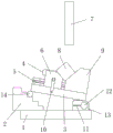
in the figure: 1. a fixed base; 2. an angle block; 3. rotating the base; 4. a movable limiting block; 5. a guide rail; 6. a bevel slider; 7. grinding through a grinding wheel; 8. a workpiece; 9. a magnetic stage with an inclined surface; 10. a slider locks the wrench; 11. fixing the bolt; 12. a rotating shaft; 13. a fixed block; 14. and (4) a support column.
Detailed Description
The technical solutions in the embodiments of the present invention will be clearly and completely described below with reference to the drawings in the embodiments of the present invention, and it is obvious that the described embodiments are only a part of the embodiments of the present invention, and not all of the embodiments. All other embodiments, which can be derived by a person skilled in the art from the embodiments given herein without making any creative effort, shall fall within the protection scope of the present invention.
Examples
Referring to fig. 1-3, the present invention provides the following technical solutions: the utility model provides a precision angle machining auxiliary device of grinding machine, wear emery wheel 7 including unable adjustment base 1 and mill, work piece 8, the fixed angle piece 2 that is provided with in 1 top one side of unable adjustment base, 1 upper end of unable adjustment base still is provided with rotating base 3, 3 upper surface symmetries of rotating base are provided with two guide rails 5, two guide rails 5 outer ends slide and are provided with inclined plane slider 6, and 6 lower surfaces of inclined plane slider still at 3 upper surface of rotating base slip, 3 upper surface one side of rotating base is fixed and is provided with inclined plane magnetic table 9, 6 both ends of inclined plane slider are provided with the slider locking spanner 10 of symmetry, 2 one side symmetries of angle piece are kept away from at the 1 top of unable adjustment base and are provided with two fixed blocks 13, thereby slider locking spanner 10 corresponds the contained angle with rotating base 3 when using and presss from both sides tightly inclined plane slider 6 spacing in 5 outer ends.
Specifically, two fixed blocks 13 are inside to run through and to rotate and be connected with pivot 12, and pivot 12 and 3 lower surface one end fixed connection of rotating base, and rotating base 3 keeps away from 2 one of connection angle piece upper surfaces at unable adjustment base 1 through fixed block 13, pivot 12 rotation connection.
Specifically, angle piece 2 is the echelonment setting towards 3 one ends of rotating base, and the ladder upper end has support column 14 with the 3 lower surface of rotating base centre gripping in the position that correspond, and support column 14 homoenergetic puts on every ladder in this embodiment, and ladder length and height are even setting, and a plurality of ladders play the regulatory function, have accomplished polishing of 8 different angles of work piece.
Specifically, the fixed block 13 is kept away from 12 one ends of pivot and is run through from top to bottom and offer the screw that is used for fixing bolt 11 to close soon, and fixed block 13 one side sets up for the opening in this embodiment, makes and connects 12 parts of pivot and forms elastic construction, and the rotation of the pivot 12 of being convenient for is adjusted and spacing.
It is specific, inclined plane magnetic table 9 is close to inclined plane slider 6 one side inclined plane and inclined plane slider 6 and is close to the inclined plane magnetic table 9 inclined plane and mutually supports the use, placed work piece 8 on inclined plane slider 6 and the inclined plane magnetic table 9 inclined plane, 11 lower extremes of fixing bolt run through fixed block 13 and close with 1 inside soon of unable adjustment base in this embodiment, fixing bolt 11 and unable adjustment base 1 are the shell with 13 upper end opening centre gripping of fixed block promptly when revolving, thereby it is spacing to carry out pivot 12 and rotating base 3, play the positioning action after the regulation.
Specifically, still including activity stopper 4, activity stopper 4 is fixed to be set up and extends in 9 side surfaces on inclined plane magnetic table and to 6 one sides of inclined plane slider, blocks the one end on inclined plane slider 6, 9 inclined planes on inclined plane magnetic table, and activity stopper 4 is used for the location of work piece 8 one side in this embodiment, and the one end that slides work piece 8 after work piece 8 and inclined plane slider 6, 9 inclined planes on inclined plane magnetic table contact is close to with activity stopper 4 to stability when guaranteeing to polish.
The working principle and the using process of the utility model are as follows: the fixed base 1 is fixed on a working platform of a grinding machine, firstly, a slide block locking wrench 10 is loosened according to the size of a workpiece 8 to adjust the inclined plane slide block 6 to a proper position and then locked, the workpiece 8 is placed at an included angle formed by the inclined plane slide block 6 and the inclined plane magnetic table 9, and one end of the workpiece 8 abuts against the inner side surface of the movable limiting block 4. And loosening the fixing bolt 11, cushioning the supporting column 14 at the corresponding height of the angle block 2 according to the required angle of the workpiece 8, locking the fixing bolt 11, and finally machining the angle of the workpiece in place by using a grinding wheel.
Finally, it should be noted that: although the present invention has been described in detail with reference to the foregoing embodiments, it will be apparent to those skilled in the art that changes may be made in the embodiments and/or equivalents thereof without departing from the spirit and scope of the utility model. Any modification, equivalent replacement, or improvement made within the spirit and principle of the present invention should be included in the protection scope of the present invention.
Claims (6)
1. The utility model provides a accurate angle processing auxiliary device of grinding machine, includes unable adjustment base (1) and wears emery wheel (7), work piece (8), its characterized in that: the fixed angle piece (2) that is provided with in unable adjustment base (1) top one side, unable adjustment base (1) upper end still is provided with rotating base (3), rotating base (3) upper surface symmetry is provided with two guide rails (5), two guide rail (5) outer end slides and is provided with inclined plane slider (6), just inclined plane slider (6) lower surface still is at rotating base (3) upper surface slip, rotating base (3) upper surface one side is fixed and is provided with inclined plane magnetic table (9), inclined plane slider (6) both ends are provided with slider locking spanner (10) of symmetry, unable adjustment base (1) top is kept away from angle piece (2) one side symmetry and is provided with two fixed blocks (13).
2. The precise angle machining auxiliary device of the grinding machine as claimed in claim 1, wherein: two fixed block (13) inside runs through and rotates and is connected with pivot (12), just pivot (12) and rotating base (3) lower surface one end fixed connection, rotating base (3) are rotated through fixed block (13), pivot (12) and are connected and keep away from connection angle piece (2) one and serve the upper surface in fixed base (1).
3. The precise angle machining auxiliary device of the grinding machine as claimed in claim 1, wherein: the angle block (2) is arranged in a ladder shape towards one end of the rotating base (3), and a supporting column (14) is clamped at the corresponding position of the upper end of the ladder and the lower surface of the rotating base (3).
4. The precise angle machining auxiliary device of the grinding machine as claimed in claim 1, wherein: and one end of the fixing block (13), which is far away from the rotating shaft (12), penetrates up and down to be provided with a screw hole for screwing the fixing bolt (11).
5. The precise angle machining auxiliary device of the grinding machine as claimed in claim 1, wherein: the inclined plane magnetic table is characterized in that an inclined plane on one side, close to the inclined plane sliding block (6), of the inclined plane magnetic table (9) and an inclined plane on one side, close to the inclined plane magnetic table (9), of the inclined plane sliding block (6) are matched with each other for use, and a workpiece (8) is placed on the inclined planes of the inclined plane sliding block (6) and the inclined plane magnetic table (9).
6. The precise angle machining auxiliary device of the grinding machine as claimed in claim 1, wherein: still including activity stopper (4), activity stopper (4) are fixed to be set up and extend to inclined plane slider (6) one side at inclined plane magnetic table (9) one side surface, block inclined plane slider (6), the one end on inclined plane magnetic table (9) inclined plane.
Priority Applications (1)
| Application Number | Priority Date | Filing Date | Title |
|---|---|---|---|
| CN202122986582.3U CN216265391U (en) | 2021-12-01 | 2021-12-01 | Accurate angle processing auxiliary device of grinding machine |
Applications Claiming Priority (1)
| Application Number | Priority Date | Filing Date | Title |
|---|---|---|---|
| CN202122986582.3U CN216265391U (en) | 2021-12-01 | 2021-12-01 | Accurate angle processing auxiliary device of grinding machine |
Publications (1)
| Publication Number | Publication Date |
|---|---|
| CN216265391U true CN216265391U (en) | 2022-04-12 |
Family
ID=81040384
Family Applications (1)
| Application Number | Title | Priority Date | Filing Date |
|---|---|---|---|
| CN202122986582.3U Active CN216265391U (en) | 2021-12-01 | 2021-12-01 | Accurate angle processing auxiliary device of grinding machine |
Country Status (1)
| Country | Link |
|---|---|
| CN (1) | CN216265391U (en) |
-
2021
- 2021-12-01 CN CN202122986582.3U patent/CN216265391U/en active Active
Similar Documents
| Publication | Publication Date | Title |
|---|---|---|
| GB1422908A (en) | Grinding machines | |
| CN216179344U (en) | Polishing equipment based on mechanical polishing | |
| CN216265391U (en) | Accurate angle processing auxiliary device of grinding machine | |
| CN216883179U (en) | Head walking type follow-up grinding machine suitable for processing inner and outer curves | |
| CN213319406U (en) | Grinding machine workbench | |
| CN214642583U (en) | High-precision grinding machine | |
| CN211490954U (en) | Grinding machine with stable clamping function | |
| CN215239767U (en) | Lengthened lathe bed taper hole grinder | |
| CN208961718U (en) | A kind of multi-angle polished lathe | |
| CN208214987U (en) | A kind of interior base cylindrical grinder | |
| CN217702773U (en) | Grinding machine clamping device with good stability for wood processing | |
| CN214025045U (en) | Precision grinding machine for machining | |
| CN219235017U (en) | Flat grinder | |
| CN2038836U (en) | Woodworking machine with a planer sharpener | |
| CN216327259U (en) | Grinding machine for machining center | |
| CN216707034U (en) | Wood working is with deciding thick grinder that has automatic thickness measurement structure | |
| CN213646919U (en) | High-precision grinding tool manufacturing hand-operated surface grinding machine | |
| CN215617114U (en) | Grinding machine for machining die parts | |
| CN215147594U (en) | Grinding machine with chamfering auxiliary positioning device for machining die steel | |
| CN217394602U (en) | Grinding machine convenient for processing plate blank water gaps with different specifications | |
| CN215616943U (en) | Fine surface grinding machine for producing precise die parts | |
| CN215967997U (en) | Arc-shaped workpiece polisher convenient to adjust and used for machinery | |
| CN217255019U (en) | Drill bit grinding clamp holder | |
| CN216802884U (en) | Anti-deviation grinding machine for machining precision die | |
| CN217413507U (en) | Auxiliary device of sander |
Legal Events
| Date | Code | Title | Description |
|---|---|---|---|
| GR01 | Patent grant | ||
| GR01 | Patent grant |