CN216239749U - Building templates connection structure - Google Patents
Building templates connection structure Download PDFInfo
- Publication number
- CN216239749U CN216239749U CN202122311769.3U CN202122311769U CN216239749U CN 216239749 U CN216239749 U CN 216239749U CN 202122311769 U CN202122311769 U CN 202122311769U CN 216239749 U CN216239749 U CN 216239749U
- Authority
- CN
- China
- Prior art keywords
- template
- threaded rod
- panel
- pair
- holes
- Prior art date
- Legal status (The legal status is an assumption and is not a legal conclusion. Google has not performed a legal analysis and makes no representation as to the accuracy of the status listed.)
- Active
Links
Images


Landscapes
- Mutual Connection Of Rods And Tubes (AREA)
Abstract
The utility model relates to a building template connecting structure, which comprises two rows of templates, wherein each template comprises template units, the template units are connected with first steel pipes through connecting hooks, each template unit comprises a frame pipe and a panel provided with a first pair of pulling holes, each frame pipe is provided with a second pair of pulling holes, and a drawn wire penetrates through the two opposite template units and is connected with the second steel pipes through the connecting hooks; the frame pipe is provided with a limit hole which is arranged oppositely; the connecting hook comprises a threaded rod, an inserting rod is fixed at one end of the threaded rod, a locking nut is connected onto the threaded rod in a threaded mode, a clamping block is sleeved on the threaded rod, an ejector rod is fixed on the clamping block, and the clamping block is provided with an arc-shaped clamping groove matched with the first steel pipe or the second steel pipe. The utility model can effectively reduce the construction cost of the template, reduce the labor intensity of constructors and improve the installation efficiency.
Description
Technical Field
The utility model relates to the technical field of building template installation, in particular to a building template connecting structure.
Background
The building formwork is a temporary supporting structure, which is manufactured according to the design requirements, so that the concrete structure and the members are formed according to the specified positions and geometric dimensions, the correct positions of the concrete structure and the members are kept, and the self weight of the building formwork and the external load acting on the building formwork are borne. The purpose of the template engineering is to ensure the quality and the construction safety of the concrete engineering, accelerate the construction progress and reduce the engineering cost.
A building template structure for cast-in-place concrete structural engineering construction mainly comprises a panel, a supporting structure and a connecting piece. The panel is a bearing plate directly contacting with newly cast concrete; the supporting structure is a temporary structure for supporting the panel, the concrete and the construction load, so that the building template structure is firmly combined and is not deformed or damaged; the connecting piece is a fitting for integrally connecting the panel and the support structure.
At present, the templates are usually connected by using a connecting plate, and the two opposite templates for pouring the wall are fixed in a pulling mode through wire drawing. As shown in fig. 1, the connecting plates are provided with pull holes for passing the drawn wires, the two opposite templates are fixed between the two connecting plates in a pulling mode through the drawn wires, the drawn wires are sleeved with hooks and threaded connection nuts on the back surfaces of the two templates, the upper portion and the lower portion of each hook are respectively provided with a steel pipe, and the nuts are used for tightly supporting the steel pipes and the templates. This type of connection has the following problems:
firstly, because a connecting plate is needed between two adjacent templates and each clamping hook needs two steel pipes for fixing, the material consumption of the connecting plate and the steel pipes is excessive, and the cost is increased;
and secondly, the operation of manually installing and disassembling the template is troublesome, and the labor cost is high.
SUMMERY OF THE UTILITY MODEL
Aiming at the defects of the prior art, the utility model provides a building template connecting structure, which is characterized in that a first pair of pull holes and a second pair of pull holes are formed in a panel and a frame pipe through an improved structure, a connecting lock and a second steel pipe are matched to connect a single-row template and simultaneously oppositely pull and fix the template, so that materials are saved, the labor intensity of constructors is reduced, and the cost is reduced.
The utility model is realized by the following technical scheme:
provides a building template connecting structure, which comprises two rows of templates which are oppositely arranged, wherein each row of templates comprises a plurality of template units, the adjacent template units of each row are connected with a first steel pipe through connecting hooks, each template unit comprises a panel and frame pipes which are uniformly fixed on one surface of the panel,
the panel is provided with a first pair of pulling holes,
the frame pipe is provided with a second pair of drawing holes opposite to the first pair of drawing holes on two sides parallel to the panel, drawn wires penetrate through the first pair of drawing holes and the second pair of drawing holes between the two opposite template units, the drawn wires are respectively sleeved on the back surfaces of the two template units and are respectively provided with a limiting block adjusted through a nut, and a second steel pipe is arranged between the limiting block and the frame pipe corresponding to the panel unit; the frame pipe is evenly provided with limiting holes which are arranged oppositely on two opposite surfaces which are vertical to the panel;
the connecting hook comprises a threaded rod, an inserted bar matched with the limiting hole is fixed at one end of the threaded rod, a locking nut is connected to the threaded rod in a threaded mode, a clamping block is sleeved on the threaded rod between the locking nut and the inserted bar, an ejector rod which is parallel to the threaded rod and matched with the frame pipe is fixed on one side of the threaded rod of the clamping block, and an arc-shaped clamping groove matched with the first steel pipe or the second steel pipe is formed in the other side of the threaded rod of the clamping block.
This scheme is through seting up first a pair of trompil on the panel, set up on the frame pipe right and to the trompil, cooperation coupling hook and second steel pipe carry out the connection of drawing, and usable coupling hook and first steel pipe are connected adjacent template unit simultaneously, compare in the connecting plate connection of prior art, and are more convenient, and simple to operate, and the improvement of coupling hook can effectively reduce the use amount of steel pipe when guaranteeing template joint strength, reduces constructor's intensity of labour.
Furthermore, the axis of at least two limiting holes on the frame pipe which is positioned on the back of the panel and is opposite to the first pair of pulling holes on the panel is vertically intersected with the axis of the second pair of pulling holes on the frame pipe.
The limiting holes arranged on the frame pipes are vertically intersected with the second opposite-pulling holes in the frame pipes, so that a small second steel pipe can be used between the limiting blocks and the panel when the two templates are oppositely pulled, the first steel pipe can be shared, the two second steel pipes can be prevented from being used for opposite pulling, the labor intensity of constructors can be reduced, and the two templates can be conveniently disassembled and assembled.
The utility model has the beneficial effects that:
the first counter-drawing holes are formed in the face plate of the template unit, the second counter-drawing holes which are opposite to each other are formed in the frame pipe at the back of the face plate, the drawn wires penetrate through the first counter-drawing holes and the second counter-drawing holes and are fixed with the second steel pipe through the limiting blocks, counter-drawing of the templates is achieved, the template units in the same row are connected with the first steel pipe in a matched mode through the connecting hooks, ejector rods of the connecting hooks abut against the frame pipe, the first steel pipe does not need to be arranged, compared with the connecting plate connection mode adopted at present, the connection mode is more convenient, the arrangement quantity of the first steel pipe is reduced, meanwhile, the limiting holes formed in the frame pipe are vertically intersected with the second counter-drawing holes in the frame pipe, when the template units are counter-drawn, the limiting blocks on the drawn wires can share the second steel pipe connected between the templates, the using amount of the first steel pipe is saved, the assembly strength of constructors can be effectively reduced, and the assembly efficiency is improved, the labor cost is reduced and the expenditure is saved.
Drawings
FIG. 1 is a schematic view of the overall structure of the present invention;
FIG. 2 is an enlarged view of the point A in FIG. 1;
FIG. 3 is a schematic view of the connecting lock of the present invention;
FIG. 4 is a schematic structural view of a rack pipe of the present invention with the back of the panel facing the first pair of pull holes;
FIG. 5 is a schematic diagram of the structure of the template unit of the present invention;
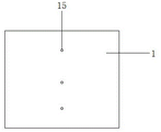
FIG. 6 is a front view of the panel of the template unit of the present invention.
Shown in the figure:
1. the panel, 2, a frame pipe, 3, second steel pipe, 4, stopper, 5, fixture block, 6, inserted bar, 7, threaded rod, 8, lock nut, 9, arc draw-in groove, 10, ejector pin, 11, spacing hole, 12, second counter-pull hole, 13, first steel pipe, 14, wire drawing, 15, first counter-pull hole.
Detailed Description
In order to clearly illustrate the technical features of the present solution, the present solution is explained below by way of specific embodiments.
The utility model provides a building templates connection structure, includes two rows of templates of relative setting, and every row of template includes a plurality of template unit, connects through coupling hook and first steel pipe 13 between every row of adjacent template unit, and the template unit includes panel 1 and evenly fixes the frame pipe 2 in panel 1 one side, has seted up first counter-bore 15 on the panel 1.
A second pair of drawing holes 12 opposite to the first pair of drawing holes 15 are formed in two sides of the frame pipe 2 parallel to the panel 1, drawing wires 14 penetrate through the first pair of drawing holes 15 and the second pair of drawing holes 12 between the two opposite template units, the drawing wires 14 are respectively sleeved on the back sides of the two template units and are respectively provided with a limiting block 4 adjusted through a nut, and a second steel pipe 3 is arranged between the limiting block 4 and the frame pipe 2 corresponding to the panel unit; the frame tube 2 is evenly provided with limiting holes 11 which are arranged oppositely on two opposite surfaces which are vertical to the panel 1.
The connecting hook includes threaded rod 7, and the one end of threaded rod 7 is fixed with inserted bar 6 that matches with spacing hole 11, and threaded connection has lock nut 8 on the threaded rod 7, and threaded rod 7 overlaps between lock nut 8 and inserted bar 6 to be equipped with fixture block 5, and fixture block 5 is fixed with in one side of threaded rod 7 parallel with threaded rod 7 and with frame pipe 2 complex ejector pin 10, fixture block 5 be equipped with at the opposite side of threaded rod 7 with first steel pipe 13 or 3 complex arc draw-in grooves 9 of second steel pipe.
Taking the height of the template as 1.25m as an example, the template is spliced and extended through the template units in the width direction. The panel one side of every template unit is fixed with the frame pipe 2 of five vertical settings, and every template unit evenly distributed has three first pair of hand-hole 15 on the central line of direction of height panel, offers on the frame pipe 2 at the 1 back of panel simultaneously with three first pair of hand-hole 15 just right three second to hand-hole 12, is located the frame pipe 2 of intermediate position and is located and offers second to hand-hole 12 and spacing hole 11 on the frame pipe 2 of 1 both sides position of panel respectively, wherein: the number of the second counter-pulling holes 12 is three, and the number of the limiting holes 11 is eight. As an embodiment of the utility model, three second counter-pulling holes 12 are arranged on the frame tube 2 and are vertically crossed with the axes of the three limiting holes 11 on the frame tube 2.
When the template unit installation tool is used, the template units are transversely spliced, the frame pipes 2 at the joint of the two template units are connected by the connecting hooks, the positions of the limiting holes 11 on the two frame pipes 2 of the two template units are aligned and communicated, the inserting rods 6 of the connecting hooks are respectively inserted into the limiting holes 11 of the two frame pipes 2, the fixture block 5 on the threaded rod 7 is adjusted to enable the ejector rod 10 on the fixture block 5 to be abutted against one frame pipe 2, the transversely arranged first steel pipe 13 is placed in the arc-shaped clamping groove 9 on one side of the fixture block 5, and the fixture block 5 is tightly pressed against the first steel pipe 13 and the frame pipes 2 by screwing the nut 8 to realize the installation of the adjacent template units. When connecting the opposite drawing between the relative template, run through respectively with wire drawing 14 just in the first pair of draw hole 15 and the second pair draw hole 12 to two template units, wire drawing 14 overlaps respectively at the back of two template units and is equipped with stopper 4 through the nut regulation, stopper 4 is equipped with two curved recesses, one of them recess offsets with first steel pipe 13, and another recess realizes that this recess offsets with second steel pipe 3 through placing second steel pipe 3 on frame pipe 2, utilize the nut to lock stopper 4 on threaded rod 7 and make wire drawing 14 can fix between two template units, and then accomplish the installation of template.
Of course, the above description is not limited to the above examples, and the undescribed technical features of the present invention can be implemented by or using the prior art, and will not be described herein again; the above embodiments and drawings are only for illustrating the technical solutions of the present invention and not for limiting the present invention, and the present invention has been described in detail with reference to the preferred embodiments, it should be understood by those skilled in the art that changes, modifications, additions or substitutions within the spirit and scope of the present invention may be made by those skilled in the art without departing from the spirit of the present invention, and shall also fall within the scope of the claims of the present invention.
Claims (2)
1. The utility model provides a building templates connection structure, includes two rows of templates of relative setting, and every row of template includes a plurality of template unit, its characterized in that: each row of adjacent template units are connected with the first steel pipe through a connecting hook, each template unit comprises a panel and frame pipes uniformly fixed on one surface of the panel,
the panel is provided with a first pair of pulling holes,
the frame pipe is provided with a second pair of drawing holes opposite to the first pair of drawing holes on two sides parallel to the panel, drawn wires penetrate through the first pair of drawing holes and the second pair of drawing holes between the two opposite template units, the drawn wires are respectively sleeved on the back surfaces of the two template units and are respectively provided with a limiting block adjusted through a nut, and a second steel pipe is arranged between the limiting block and the frame pipe corresponding to the panel unit; the frame pipe is evenly provided with limiting holes which are arranged oppositely on two opposite surfaces which are vertical to the panel;
the connecting hook comprises a threaded rod, an inserted bar matched with the limiting hole is fixed at one end of the threaded rod, a locking nut is connected to the threaded rod in a threaded mode, a clamping block is sleeved on the threaded rod between the locking nut and the inserted bar, an ejector rod which is parallel to the threaded rod and matched with the frame pipe is fixed on one side of the threaded rod of the clamping block, and an arc-shaped clamping groove matched with the first steel pipe or the second steel pipe is formed in the other side of the threaded rod of the clamping block.
2. The building template connecting structure according to claim 1, wherein: the axes of at least two limiting holes on the frame pipe which is positioned on the back of the panel and is opposite to the first pair of pulling holes on the panel are vertically intersected with the axes of the second pair of pulling holes on the frame pipe.
Priority Applications (1)
| Application Number | Priority Date | Filing Date | Title |
|---|---|---|---|
| CN202122311769.3U CN216239749U (en) | 2021-09-24 | 2021-09-24 | Building templates connection structure |
Applications Claiming Priority (1)
| Application Number | Priority Date | Filing Date | Title |
|---|---|---|---|
| CN202122311769.3U CN216239749U (en) | 2021-09-24 | 2021-09-24 | Building templates connection structure |
Publications (1)
| Publication Number | Publication Date |
|---|---|
| CN216239749U true CN216239749U (en) | 2022-04-08 |
Family
ID=80985380
Family Applications (1)
| Application Number | Title | Priority Date | Filing Date |
|---|---|---|---|
| CN202122311769.3U Active CN216239749U (en) | 2021-09-24 | 2021-09-24 | Building templates connection structure |
Country Status (1)
| Country | Link |
|---|---|
| CN (1) | CN216239749U (en) |
-
2021
- 2021-09-24 CN CN202122311769.3U patent/CN216239749U/en active Active
Similar Documents
| Publication | Publication Date | Title |
|---|---|---|
| CN114293694A (en) | Zigzag unit aluminum plate curtain wall mounting system | |
| CN216239749U (en) | Building templates connection structure | |
| CN202831617U (en) | Large-scale integrated steel template | |
| CN210917962U (en) | Steel bar truss floor support plate framework | |
| CN110593559A (en) | Concrete beam formwork supporting device and construction process thereof | |
| CN211037834U (en) | Template reinforcing system structure | |
| CN216181461U (en) | Box girder template unit | |
| CN210888076U (en) | Prefabricated assembled aluminum alloy template installation device | |
| CN217924874U (en) | A high formwork angle brace mechanism for construction | |
| CN215055557U (en) | Steel construction safety rope fixing device | |
| CN217325052U (en) | Construction system for bridge uniform-section hollow pier capping beam | |
| CN215519355U (en) | Steel tube bundle combined shear wall structure | |
| CN210263918U (en) | Anti-bank pouring die | |
| CN216921252U (en) | Scaffold | |
| CN115324234B (en) | Assembled steel construction building steel tube bundle composite wall | |
| CN216478218U (en) | Polyurethane composite material frame structure | |
| CN215107605U (en) | Firm formula reinforcing means based on building engineering uses | |
| CN217350493U (en) | Tower crane convenient to install and used for building | |
| CN214696869U (en) | Novel combined honeycomb type template | |
| CN216239750U (en) | Connecting structure for construction of building template engineering | |
| CN213356790U (en) | Fully-mechanized mining working face winch fixing device | |
| CN220133495U (en) | Combined building template | |
| CN220354219U (en) | Aluminum alloy track connecting system | |
| CN217997702U (en) | Novel light FRP grid convenient to link up | |
| CN214831971U (en) | Splicing device for bridge upright post and tie beam |
Legal Events
| Date | Code | Title | Description |
|---|---|---|---|
| GR01 | Patent grant | ||
| GR01 | Patent grant |