CN216184428U - Two-gear electric drive axle based on clutch coupling - Google Patents
Two-gear electric drive axle based on clutch coupling Download PDFInfo
- Publication number
- CN216184428U CN216184428U CN202122909525.5U CN202122909525U CN216184428U CN 216184428 U CN216184428 U CN 216184428U CN 202122909525 U CN202122909525 U CN 202122909525U CN 216184428 U CN216184428 U CN 216184428U
- Authority
- CN
- China
- Prior art keywords
- gear
- clutch
- transmission gear
- axle housing
- transmission
- Prior art date
- Legal status (The legal status is an assumption and is not a legal conclusion. Google has not performed a legal analysis and makes no representation as to the accuracy of the status listed.)
- Active
Links
Images


Abstract
The utility model discloses a two-gear electric drive axle based on clutch coupling, which belongs to the technical field of power assemblies and comprises a left half shaft, a right half shaft, a drive motor, a first transmission gear, a differential mechanism, a third transmission gear, a planetary transmission mechanism, a locking clutch, a clutch and a second transmission gear; the first transmission gear is connected with the motor rotor and meshed with the second transmission gear; the second transmission gear is connected with the sun gear; the planet carrier is connected with a third transmission gear; the third transmission gear is meshed with the differential. Power is output to the sun gear through the first transmission gear and the second transmission gear, different coupling forms are achieved through combination and separation of the clutch and the locking clutch, and power is distributed to the two half shafts through the differential mechanism to achieve power transmission. By integrating the driving motor, the clutch and the axle and eliminating a transmission shaft, the power system is more compact, and the space and the weight are reduced; effectively improves the dynamic property and the economical efficiency, and is convenient for realizing the specialization of the chassis and the serialization of the power assembly.
Description
Technical Field
The utility model belongs to the technical field of power assemblies, and particularly relates to a two-gear electric drive axle based on clutch coupling.
Background
The technology of the electric drive system of the new energy automobile generally develops towards the direction of integration and integration of a power system. Through the integrated design, on one hand, the volume and the weight of the assembly can be further reduced, and the power, the volume and the torque density of the system are improved; on the other hand, through the matching of integration and refinement, the NVH level of the electric drive assembly is improved, the series and batch production are facilitated, the universality of the product is improved, and the development and production cost is reduced.
At present, the scheme that a motor is matched with an AMT (automated mechanical transmission) gearbox and a motor is matched with a speed reducer is adopted for a new energy commercial vehicle electric drive axle, and multiple gear shifting execution mechanisms realize the coupling and transmission of power, so that the system integration level is low, the power assembly occupies large space and volume, the weight is large, the reliability of the gear shifting execution mechanism is low, the gear shifting control logic difficulty is high, and the large-scale cost-free advantage is achieved.
SUMMERY OF THE UTILITY MODEL
In order to solve the problems, the utility model provides a two-gear electric drive axle based on clutch coupling, which is characterized in that a drive motor, a clutch and an axle are integrated, a transmission shaft is omitted, a power system is more compact, and the space and the weight are reduced.
The utility model is realized by the following technical scheme:
a two-gear electric drive axle based on clutch coupling comprises a left half shaft, a right half shaft, a drive motor, a first transmission gear, a differential, a third transmission gear, a planetary transmission mechanism, a locking clutch, a clutch and a second transmission gear, wherein the drive motor, the first transmission gear, the differential, the third transmission gear, the planetary transmission mechanism, the locking clutch, the clutch and the second transmission gear are integrally installed in an axle housing of a vehicle body;
the planetary transmission mechanism comprises a sun gear, a planet carrier gear and a gear ring which are sequentially meshed from the center to the outer side;
the first transmission gear is connected with a motor rotor of the driving motor and meshed with the second transmission gear;
the second transmission gear is connected with the sun gear through a first mandrel;
the clutch is arranged on the first mandrel and is used for clutching the planet carrier;
the locking clutch is mounted on the axle housing of the vehicle body and is used for clutching the gear ring;
the planet carrier is connected with the third transmission gear through a second mandrel;
the third transmission gear is meshed with an integrated gear outside the differential;
the left half shaft penetrates through the middle part of the motor rotor in a sliding manner and is connected with one side of the differential mechanism; the right half shaft is connected with the other side of the differential; and the left half shaft and the right half shaft are respectively provided with a left wheel and a right wheel.
The utility model is further improved in that a sleeve for the sliding penetration of the left half shaft is arranged in the middle of the motor rotor, and the sleeve is connected and installed with the axle housing of the vehicle body through a bearing; the first transmission gear is sleeved on the sleeve.
In a further improvement of the utility model, the second transmission gear, the clutch and the sun gear are coaxially connected through splines and rotatably mounted on the axle housing of the vehicle body through a bearing.
The utility model is further improved in that two output gears of the differential are respectively provided with a supporting bearing which is connected and installed with the axle housing of the vehicle body.
In addition, the utility model is further improved, and the vehicle body axle housing comprises a main axle housing and an auxiliary axle housing; the main axle housing is arranged on the outer sides of the driving motor, the first transmission gear, the left half shaft, the differential mechanism and the right half shaft, and the auxiliary axle housing is arranged on the outer sides of the third transmission gear, the planetary transmission mechanism, the locking clutch, the clutch and the second transmission gear; the main axle housing and the auxiliary axle housing are correspondingly provided with transmission connecting channels and are connected and installed through bolts.
In addition, the main axle housing is an integral stamping and welding part.
In addition, the utility model is further improved in that a motor stator of the driving motor is rigidly and integrally connected with the axle housing of the vehicle body.
The utility model is further improved in that a cooling water channel surrounding the motor stator is arranged in the axle housing of the vehicle body, and the cooling water channel is connected with a cooling circulation driving assembly.
According to a further improvement of the present invention, the driving motor is a permanent magnet synchronous motor.
According to the technical scheme, the utility model has the beneficial effects that:
the power is output to a sun gear of the planetary transmission mechanism through a first transmission gear and a second transmission gear by the rotation of a motor rotor of the driving motor, different coupling forms of the power can be realized through the combination and the separation of a clutch and a locking clutch, and finally the power is distributed to two half shafts through a differential mechanism integrated with a gear and finally transmitted to wheels, so that the power transmission is realized. The integrated driving device has the advantages that the integrated driving device is simple in overall structure and high in integration level, and a driving shaft is omitted by integrating the driving motor, the clutch and the axle, so that a power system is more compact, and the space and the weight are reduced; the dynamic property and the economical efficiency of the new energy commercial vehicle are effectively improved, and the chassis specialization and the power assembly serialization are convenient to realize. The integrated design of the electric axle is not only an innovation of the structure, but also the self-assembly power assembly system simplifies the design of the whole chassis, saves the space of the chassis and reduces the noise. The electric drive axle is beneficial to realizing the modularization of a drive motor system and is convenient for realizing the extension of seriation of axles with different tonnages.
Drawings
In order to more clearly illustrate the technical solution of the present invention, the drawings used in the description will be briefly introduced, and it is obvious that the drawings in the following description are only some embodiments of the present invention, and it is obvious for those skilled in the art that other drawings can be obtained based on these drawings without creative efforts.
FIG. 1 is a schematic diagram of the transmission principle of an embodiment of the present invention.
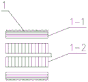
Fig. 2 is a schematic structural diagram of a driving motor according to an embodiment of the present invention.
Fig. 3 is a schematic diagram of an operation mode of the embodiment of the present invention.
In the drawings: 1. the driving motor comprises a driving motor 1-1, a motor stator 1-2, a motor rotor 2, a first transmission gear 3, a left half shaft 4, a differential mechanism 5, a right half shaft 6, a right wheel 7, a third transmission gear 8, a planet carrier 9, a gear ring 10, a locking clutch 11, a sun gear 12, a clutch 13, a second transmission gear 14 and a left wheel.
Detailed Description
In order to make the objects, features and advantages of the present invention more obvious and understandable, the technical solutions of the present invention will be clearly and completely described below with reference to the accompanying drawings in the present embodiment, and it is apparent that the embodiments described below are only a part of embodiments of the present invention, and not all embodiments. All other embodiments, which can be derived by a person skilled in the art from the embodiments given herein without making any creative effort, shall fall within the scope of protection of this patent.
As shown in FIG. 1, the utility model discloses a two-gear electric drive axle based on clutch coupling, which comprises a left half shaft 3, a right half shaft 5, a drive motor 1, a first transmission gear 2, a differential 4, a third transmission gear 7, a planetary transmission mechanism, a locking clutch 10, a clutch 12 and a second transmission gear 13, wherein the drive motor 1, the first transmission gear 2, the differential 4, the third transmission gear 7, the planetary transmission mechanism, the locking clutch 10, the clutch 12 and the second transmission gear 13 are integrally installed in an axle housing of a vehicle body;
the planetary transmission mechanism comprises a sun gear 11, planet carrier gears and a gear ring 9 which are sequentially meshed from the center to the outer side, and the planet carrier gears are connected and installed through a planet carrier 8;
the first transmission gear 2 is connected with a motor rotor 1-2 of the driving motor 1 and is meshed with the second transmission gear 13;
the second transmission gear 13 is connected with the sun gear 11 through a first mandrel;
the clutch 12 is mounted on the first mandrel and is used for performing clutch action on the planet carrier 8;
the locking clutch 10 is mounted on the axle housing of the vehicle body and is used for performing clutch action on the gear ring 9;
the planet carrier 8 is connected with the third transmission gear 7 through a second mandrel;
the third transmission gear 7 is meshed with an integrated gear outside the differential 4;
the left half shaft 3 penetrates through the middle part of the motor rotor 1-2 in a sliding manner and is connected with the output end on one side of the differential mechanism 4; the right half shaft 5 is connected with the output end of the other side of the differential 4; and a left wheel 14 and a right wheel 6 are respectively arranged on the left half shaft 3 and the right half shaft 5.
Through the rotation of a motor rotor 1-2 of a driving motor 1, power is output to a sun gear 11 of a planetary transmission mechanism through a first transmission gear 2 and a second transmission gear 13, different coupling forms of the power can be realized through the combination and the separation of a clutch 12 and a locking clutch 10, and finally the power is distributed to two half shafts through a differential mechanism 4 integrated with a gear and finally transmitted to wheels, so that the transmission of the power is realized. The integrated driving device has the advantages that the integrated driving device is simple in overall structure and high in integration level, and a driving shaft is omitted by integrating the driving motor, the clutch and the axle, so that a power system is more compact, and the space and the weight are reduced; the dynamic property and the economical efficiency of the new energy commercial vehicle are effectively improved, and the chassis specialization and the power assembly serialization are convenient to realize. The integrated design of the electric axle is not only an innovation of the structure, but also the self-assembly power assembly system simplifies the design of the whole chassis, saves the space of the chassis and reduces the noise. The electric drive axle is beneficial to realizing the modularization of a drive motor system and is convenient for realizing the extension of seriation of axles with different tonnages.
As shown in fig. 3, by engaging and disengaging the clutch 12 and the lock-up clutch 10, the following four operation modes can be realized:
EV1 mode: the clutch 12 is disengaged and the lock-up clutch 10 engaged, which achieves the maximum drive ratio of the electric drive axle for starting, hard acceleration or climbing a large hill. Power passes through the motor rotor 1-2 to the first transmission gear 2, is transmitted to the sun gear 11 of the planetary transmission mechanism through meshing with the second transmission gear 13, can be input and transmitted to the planet carrier 8 to be output through the sun gear 11 due to the separation of the clutch 12, passes through the third transmission gear 7, and is transmitted to the wheels 14 and 6 through the two half shafts 3 and 5 by meshing with the differential gear 4 integrated with the gears.
EV2 mode: the clutch 12 is engaged and the lock-up clutch 10 is disengaged, which achieves minimum drive ratio for electric drive axle for smooth road start and medium and high speed driving. The power passes through the first transmission gear 2 via the motor rotor 1-2 and is transmitted to the sun gear 11 of the planetary transmission mechanism by meshing with the second transmission gear 13, and due to the combination of the clutch 12, the sun gear 11 is locked with the planet carrier 8, passes through the planet carrier 8 and is transmitted to the wheels 14 and 6 via the two half shafts 3 and 5 by meshing with the gear of the differential mechanism 4 integrated with the gear.
Parking mode: the clutch 12 is engaged, the lock-up clutch 10 is engaged, and power cannot be transmitted, and the parking mode is entered.
Neutral mode: the clutch 12 is disengaged, the lock-up clutch 10 is disengaged, and the vehicle enters a neutral sliding mode, so that the motor is not driven to rotate when the vehicle slides, which is particularly important in a multi-shaft driving vehicle.
As shown in fig. 1-2, a sleeve for the left half shaft 3 to slidably penetrate is arranged in the middle of a motor rotor 1-2 of the driving motor 1, and the sleeve is connected and mounted with the axle housing of the vehicle body through a bearing; the first transmission gear 2 is sleeved on the sleeve and is positioned and installed through a spline. The first transmission gear 2 is reliably connected with the motor rotor 1-2 through the sleeve, and transmission accuracy and reliability are guaranteed.
The second transmission gear 13, the clutch 12 and the sun gear 11 are coaxially connected through splines and rotatably mounted on the axle housing of the vehicle body through a bearing. Simple structure, the dismouting is convenient, guarantees driven accuracy nature and stability.
And the two output gears of the differential 4 are respectively provided with a supporting bearing which is connected with the axle housing of the vehicle body. The half shaft bears the weight of the axle housing of the vehicle body, and the running stability of the vehicle is guaranteed.
The vehicle body axle housing comprises a main axle housing and an auxiliary axle housing; the main axle housing is arranged on the outer sides of the driving motor 1, the first transmission gear 2, the left half shaft 3, the differential mechanism 4 and the right half shaft 5, and the auxiliary axle housing is arranged on the outer sides of the third transmission gear 7, the planetary transmission mechanism, the locking clutch 10, the clutch 12 and the second transmission gear 13; the main axle housing and the auxiliary axle housing are correspondingly provided with transmission connecting channels and are connected and installed through bolts. The main axle housing is used for wrapping and installing the driving motor 1, the first transmission gear 2 and the differential mechanism 4, is supported and installed with the two half shafts through supporting bearings, and is connected and installed with the sleeve through a bearing; the auxiliary axle housing is used for wrapping and installing the third transmission gear 7, the planetary transmission mechanism, the locking clutch 10, the clutch 12 and the second transmission gear 13, is connected and installed with the first core shaft through a bearing, is connected and installed with the gear ring 9 through a bearing, and is fixedly installed with the locking clutch 10; the high-integration design is realized, and each bearing is used as a bearing part connected and installed with a vehicle body axle housing, so that the transmission reliability is ensured; split type design, the dismouting is convenient, overhauls easily.
Wherein, the main axle housing is an integrated punching and welding part. The main axle housing is used as a main bearing axle housing, so that the good bearing capacity is ensured, the forming is easy, and the realization is easy.
Wherein, the motor stator 1-1 of the driving motor 1 is rigidly connected with the main axle housing as a whole. The motor stator 1-1 and the main axle housing are integrated, so that the space occupation of the driving motor 1 is reduced. With driving motor 1 and automobile body axle housing degree of depth integrated as an organic whole, alleviateed the weight of axle assembly by a wide margin, reduced the energy resource consumption of whole car, promote whole car space.
And a cooling water channel surrounding the motor stator 1-1 is arranged in the axle housing of the vehicle body, and the cooling water channel is connected with a cooling circulation driving assembly. Through cooling circulation drive assembly to the coolant liquid at the cooling water course internal circulation, realize the cooling to driving motor 1, guarantee the reliability of driving motor 1 operation. Simple structure, the integrated level is high, saves space and occupies.
The driving motor 1 is a permanent magnet synchronous motor. The permanent magnet synchronous motor provides excitation by the permanent magnet, so that the structure of the motor is simpler, the processing and assembling cost is reduced, a collecting ring and an electric brush which are easy to cause problems are omitted, and the running reliability of the motor is improved; and because excitation current is not needed, excitation loss is avoided, and the efficiency and the power density of the motor are improved. The permanent magnet synchronous motor has the following advantages: the power efficiency is high, the power factor is high, no gearbox is provided, the whole transmission system is light in weight and small in heat emission; the full-closed structure is adopted, no transmission gear abrasion and noise exist, and the lubricating oil and the maintenance are avoided; the allowable overload current is large, and the reliability is high; the magnetic energy product is high, higher air gap magnetic flux density can be obtained, and the motor has smaller volume and lighter weight when the capacity is the same; the rotor has no copper loss and iron loss, and also has no friction loss of a collecting ring and an electric brush, and the running efficiency is high; the rotary inertia is small, the allowable pulse torque is large, higher acceleration can be obtained, the dynamic performance is good, the structure is compact, and the operation is reliable.
According to the two-gear electric drive axle based on clutch coupling, the motor rotor of the drive motor rotates, power is output to the sun gear of the planetary transmission mechanism through the first transmission gear and the second transmission gear, different coupling forms of power can be achieved through combination and separation of the clutch and the locking clutch, and finally the power is distributed to the two half shafts through the differential integrated with the gear and finally transmitted to the wheels, so that power transmission is achieved. The integrated driving device has the advantages that the integrated driving device is simple in overall structure and high in integration level, and a driving shaft is omitted by integrating the driving motor, the clutch and the axle, so that a power system is more compact, and the space and the weight are reduced; the dynamic property and the economical efficiency of the new energy commercial vehicle are effectively improved, and the chassis specialization and the power assembly serialization are convenient to realize. The integrated design of the electric axle is not only an innovation of the structure, but also the self-assembly power assembly system simplifies the design of the whole chassis, saves the space of the chassis and reduces the noise. The electric drive axle is beneficial to realizing the modularization of a drive motor system and is convenient for realizing the extension of seriation of axles with different tonnages.
The embodiments in the present description are described in a progressive manner, each embodiment focuses on differences from other embodiments, and the same and similar parts among the embodiments are referred to each other.
The terms "upper", "lower", "outside", "inside" and the like in the description and claims of the present invention and the above drawings are used for distinguishing relative positions if any, and are not necessarily given qualitatively. It is to be understood that the data so used is interchangeable under appropriate circumstances such that the embodiments of the utility model described herein are capable of operation in sequences other than those illustrated or described herein. Furthermore, the terms "comprising" and "having," as well as any variations thereof, are intended to cover non-exclusive inclusions.
The previous description of the disclosed embodiments is provided to enable any person skilled in the art to make or use the present invention. Various modifications to these embodiments will be readily apparent to those skilled in the art, and the generic principles defined herein may be applied to other embodiments without departing from the spirit or scope of the utility model. Thus, the present invention is not intended to be limited to the embodiments shown herein but is to be accorded the widest scope consistent with the principles and novel features disclosed herein.
Claims (9)
1. A two-gear electric drive axle based on clutch coupling is characterized by comprising a left half shaft (3), a right half shaft (5), a drive motor (1), a first transmission gear (2), a differential (4), a third transmission gear (7), a planetary transmission mechanism, a locking clutch (10), a clutch (12) and a second transmission gear (13) which are integrally installed in an axle housing of a vehicle body;
the planetary transmission mechanism comprises a sun gear (11), a planet carrier gear and a gear ring (9) which are meshed in sequence from the center to the outer side;
the first transmission gear (2) is connected with a motor rotor (1-2) of the driving motor (1) and is meshed with the second transmission gear (13);
the second transmission gear (13) is connected with the sun gear (11) through a first mandrel;
the clutch (12) is arranged on the first mandrel and is used for clutching the planet carrier (8);
the locking clutch (10) is mounted on the axle housing of the vehicle body and is used for clutching the gear ring (9);
the planet carrier (8) is connected with the third transmission gear (7) through a second mandrel;
the third transmission gear (7) is meshed with a gear outside the differential (4);
the left half shaft (3) penetrates through the middle part of the motor rotor (1-2) in a sliding manner and is connected with one side of the differential (4);
the right half shaft (5) is connected with the other side of the differential (4); and a left wheel (14) and a right wheel (6) are respectively arranged on the left half shaft (3) and the right half shaft (5).
2. Two-gear electric drive axle based on clutch coupling according to claim 1, characterized in that the middle of the motor rotor (1-2) is provided with a sleeve for the left half shaft (3) to slide through, and the sleeve is connected with the axle housing of the vehicle body through a bearing; the first transmission gear (2) is sleeved on the sleeve.
3. Two-gear electric drive axle based on clutch coupling according to claim 1, characterized in that the second transmission gear (13), the clutch (12) and the sun gear (11) are all coaxially connected by splines and rotatably mounted on the axle housing of the vehicle body by bearings.
4. Two-gear electric drive axle based on clutch coupling according to claim 1, characterized in that the differential (4) is provided with support bearings on its two output gears, respectively, which are mounted in connection with the axle housing of the vehicle body.
5. The clutch-based coupled two-speed electric drive axle of claim 1, wherein the vehicle body axle housing comprises a primary axle housing and a secondary axle housing; the main axle housing is arranged on the outer sides of the driving motor (1), the first transmission gear (2), the left half shaft (3), the differential (4) and the right half shaft (5), and the auxiliary axle housing is arranged on the outer sides of the third transmission gear (7), the planetary transmission mechanism, the locking clutch (10), the clutch (12) and the second transmission gear (13); the main axle housing and the auxiliary axle housing are correspondingly provided with transmission connecting channels and are connected and installed through bolts.
6. The clutch-based coupled two-speed electric drive axle of claim 5, wherein the main axle housing is a one-piece stamped weld.
7. Two-gear electric drive axle based on clutch coupling according to claim 1, characterized in that the motor stator (1-1) of the drive motor (1) is rigidly connected in one piece with the axle housing of the vehicle body.
8. Two-gear electric drive axle based on clutch coupling according to claim 7, characterized in that a cooling water channel surrounding the motor stator (1-1) is provided in the axle housing of the vehicle body, and a cooling circulation drive assembly is connected to the cooling water channel.
9. Two-gear drive axle based on clutch coupling according to claim 1, characterized in that the drive motor (1) is a permanent magnet synchronous motor.
Priority Applications (1)
| Application Number | Priority Date | Filing Date | Title |
|---|---|---|---|
| CN202122909525.5U CN216184428U (en) | 2021-11-24 | 2021-11-24 | Two-gear electric drive axle based on clutch coupling |
Applications Claiming Priority (1)
| Application Number | Priority Date | Filing Date | Title |
|---|---|---|---|
| CN202122909525.5U CN216184428U (en) | 2021-11-24 | 2021-11-24 | Two-gear electric drive axle based on clutch coupling |
Publications (1)
| Publication Number | Publication Date |
|---|---|
| CN216184428U true CN216184428U (en) | 2022-04-05 |
Family
ID=80914440
Family Applications (1)
| Application Number | Title | Priority Date | Filing Date |
|---|---|---|---|
| CN202122909525.5U Active CN216184428U (en) | 2021-11-24 | 2021-11-24 | Two-gear electric drive axle based on clutch coupling |
Country Status (1)
| Country | Link |
|---|---|
| CN (1) | CN216184428U (en) |
-
2021
- 2021-11-24 CN CN202122909525.5U patent/CN216184428U/en active Active
Similar Documents
| Publication | Publication Date | Title |
|---|---|---|
| CN105346410B (en) | Double-motor power drive assembly | |
| CN101722841A (en) | Power assembly for vehicles | |
| CN110920367A (en) | Coaxial two-gear electric drive axle | |
| CN108512381B (en) | Novel high-performance integrated hub motor | |
| CN104477029A (en) | Electric drive system of two-gear electric automobile | |
| CN203681266U (en) | Power system assembly of electric automobile | |
| CN113910879A (en) | Two-gear electric drive axle based on clutch coupling | |
| CN113910881B (en) | Electric drive axle based on clutch planet gear shifting | |
| CN113910880B (en) | Multimode electric drive axle based on clutch coupling | |
| CN216184428U (en) | Two-gear electric drive axle based on clutch coupling | |
| CN114475217B (en) | Three-power-source coupling hybrid system suitable for heavy truck | |
| CN215850710U (en) | Coaxial integrated double-motor double-speed-ratio electric drive assembly and electric vehicle | |
| CN110758083A (en) | New energy vehicle power system and control method thereof | |
| CN217145626U (en) | Planet gear-shifting double-motor electric drive axle | |
| CN116039364A (en) | Hybrid power system, control method of hybrid power system and vehicle | |
| CN213383878U (en) | Electric automobile and two-gear coaxial electric automobile drive axle thereof | |
| CN217145627U (en) | Double-motor electric drive axle | |
| CN204340684U (en) | A kind of power drive system of two grades of electronlmobils | |
| CN217074010U (en) | Electric drive axle assembly and vehicle | |
| CN114393982A (en) | Double-motor electric drive axle | |
| CN219339109U (en) | Electric drive axle and vehicle | |
| CN216033750U (en) | Electrically driven power transmission device | |
| CN219821116U (en) | Drive axle of vehicle and vehicle | |
| CN215513209U (en) | Electric wheel with double motors running in parallel and vehicle | |
| CN218966686U (en) | Drive axle of vehicle and vehicle |
Legal Events
| Date | Code | Title | Description |
|---|---|---|---|
| GR01 | Patent grant | ||
| GR01 | Patent grant |