CN216129255U - Novel marsh gas torch construction is with lifting transport device - Google Patents
Novel marsh gas torch construction is with lifting transport device Download PDFInfo
- Publication number
- CN216129255U CN216129255U CN202121985283.1U CN202121985283U CN216129255U CN 216129255 U CN216129255 U CN 216129255U CN 202121985283 U CN202121985283 U CN 202121985283U CN 216129255 U CN216129255 U CN 216129255U
- Authority
- CN
- China
- Prior art keywords
- fixedly connected
- plate
- motor
- shell
- hoisting device
- Prior art date
- Legal status (The legal status is an assumption and is not a legal conclusion. Google has not performed a legal analysis and makes no representation as to the accuracy of the status listed.)
- Active
Links
Images


Abstract
The utility model discloses a novel hoisting device for construction of a biogas torch in the field of construction of biogas torches, which comprises a bottom plate, wherein a first motor is fixedly connected inside the bottom plate, the top of the first motor extends to the top of the bottom plate through a rotating shaft and is fixedly connected with a supporting plate, the top of the supporting plate is fixedly connected with a shell, a lifting mechanism is arranged inside the shell, a transverse plate is fixedly connected to the top of the lifting mechanism, the left side of the bottom of the transverse plate is fixedly connected with a balancing weight through a steel rope, clamping plates are fixedly connected to both sides of the bottom plate, a fixing mechanism is arranged inside the clamping plates, a placing box is fixedly connected to the right side of the shell, a second motor is fixedly connected inside the placing box, and a rotating rod is fixedly connected to the rear end of the second motor. The utility model solves the problems that the existing lifting device is easy to deviate and turn over during working, is easy to damage articles and devices, and is inconvenient to adjust the height of a lifting hook.
Description
Technical Field
The utility model relates to the field of construction of biogas torches, in particular to a novel hoisting device for construction of a biogas torch.
Background
The biogas can not only pollute the environment, but also generate serious potential safety hazard, so anaerobic biogas needs to be treated in a centralized way, for plants or places with small gas production, the biogas collected in the centralized way is generally burnt by arranging a biogas torch, and the biogas torch has the effects of improving the safety of the places, increasing social acceptance, reducing odor pollution, reducing greenhouse effect and the like.
In marsh gas torch work progress, need use the handling device, current handling device appears squinting easily and the phenomenon of turning on one's side at the during operation, causes the harm to article and device easily, and is not convenient for adjust the height of colluding, consequently, the technical personnel in the field provide a novel handling device for marsh gas torch construction to solve the problem that proposes in the above-mentioned background art.
SUMMERY OF THE UTILITY MODEL
The utility model aims to provide a novel hoisting device for construction of a biogas torch, which aims to solve the problems in the background technology.
In order to achieve the purpose, the utility model provides the following technical scheme: a novel hoisting device for construction of a biogas torch comprises a bottom plate, wherein a first motor is fixedly connected inside the bottom plate, the top of the first motor extends to the top of the bottom plate through a rotating shaft and is fixedly connected with a supporting plate, the top of the supporting plate is fixedly connected with a shell, a lifting mechanism is arranged inside the shell, a transverse plate is fixedly connected to the top of the lifting mechanism, the left side of the bottom of the transverse plate is fixedly connected with a balancing weight through a steel rope, two sides of the bottom plate are both fixedly connected with clamping plates, a fixing mechanism is arranged inside the clamping plates, the right side of the shell is fixedly connected with a placing box, a second motor is fixedly connected inside the placing box, a rotating rod is fixedly connected to the rear end of the second motor, the rear end of the rotating rod is movably connected with the inner wall of the placing box through a bearing, and the surface of the rotating rod is fixedly connected with a steel cable winding roller, the surface of the steel cable winding roller is wound with a steel cable, and the top end of the steel cable extends to the outside of the placing box and is connected with a suspension arm through a pulley in a transmission way;
the fixing mechanism comprises a handle, a rotating plate, an inserted bar, a bolt and a support, the bottom of the handle is fixedly connected with the top of the rotating plate, the bottom of the rotating plate is fixedly connected with one end of the inserted bar, the surface of the inserted bar is respectively connected with the support and the internal threads of the clamping plate, the other end of the inserted bar extends to the bottom of the clamping plate, the bottom of the support is fixedly connected with the top of the clamping plate, one end of the bolt is connected with the top threads of the rotating plate, and the surface of the bolt is respectively connected with the internal threads of the rotating plate and the support.
As a further scheme of the utility model: elevating system includes third motor, fluted disc, pinion rack, slide bar, slider and support column, the inside fixed connection of one side and the casing of third motor, the opposite side of third motor is through one side fixed connection of pivot and fluted disc, the back of fluted disc and the positive meshing of pinion rack, the top of pinion rack and the bottom fixed connection of support column, the top of support column extend to the top of casing and with the bottom fixed connection of diaphragm, one side of slider and one side fixed connection of pinion rack, the inside of slider and the surface sliding connection of slide bar, the both ends of slide bar all with the inner wall fixed connection of casing.
As a still further scheme of the utility model: the top of the handle is fixedly connected with a rotating ball, and the cross section of the rotating ball is circular.
As a still further scheme of the utility model: the bottom fixedly connected with universal wheel of bottom plate, the quantity of universal wheel is four.
As a still further scheme of the utility model: the front surface of the shell is hinged with a box door through a hinge, and the radial section of the box door is rectangular.
As a still further scheme of the utility model: the front of bottom plate fixedly connected with control panel, control panel's front is provided with control button.
As a still further scheme of the utility model: the top of the shell is provided with a through hole, and the inside of the through hole is movably connected with the surface of the supporting column.
Compared with the prior art, the utility model has the beneficial effects that:
1. in the utility model, the support plate and the shell are driven to rotate by the first motor, the position of the suspension arm can be adjusted, the height of the suspension arm can be adjusted by arranging the lifting mechanism, the rotating rod and the steel cable are driven to rotate around the roller by the second motor, the height of the steel cable and the suspension arm can be adjusted, the rotating plate and the inserting rod are driven to rotate by the handle by the fixing mechanism, the inserting rod extends into the ground, the bottom plate can be fixed when the suspension arm works, the stability of the suspension arm is increased, the phenomenon that the bottom plate turns over or deviates is avoided, the stability of the inserting rod when the inserting rod rotates can be improved by the bracket, the rotating plate can be fixed by the bolt, the phenomenon that the rotating plate becomes loose is avoided, the counterweight property of the suspension arm for lifting an object can be improved by the counterweight block weight, the horizontal line of the suspension arm is kept, and the phenomenon that the existing lifting device easily deviates and turns over during working is solved, easily cause damage to articles and devices and are inconvenient for adjusting the height of the hook.
2. According to the lifting mechanism, the tooth disc is driven to rotate by the aid of the lifting mechanism, the tooth disc drives the toothed plate and the supporting column to lift, the height of the transverse plate can be adjusted, the stability of the toothed plate can be improved when the toothed plate lifts and lowers by the aid of the sliding block and the sliding rod, an operator holds the rotating ball to rotate, the handle can be conveniently rotated, the universal wheel is mounted at the bottom of the bottom plate and can be moved by contacting with the ground, the operator opens the box door to overhaul the interior of the shell, the control panel is mounted on the front side of the bottom plate, the operator presses the control button to control the switch of the electrical equipment, the through hole is formed in the top of the shell, and the moving range of the supporting column can be limited.
Drawings
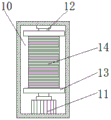
FIG. 1 is a schematic diagram of the structure of the present invention;
FIG. 2 is a cross-sectional view of the structure of the present invention;
FIG. 3 is an enlarged view of the structure A in FIG. 2 according to the present invention;
figure 4 is a schematic view of the construction of the wire rope winding roller of the present invention.
In the figure: 1. a base plate; 2. a first motor; 3. a support plate; 4. a housing; 5. a lifting mechanism; 51. a third motor; 52. a fluted disc; 53. a toothed plate; 54. a slide bar; 55. a slider; 56. a support pillar; 6. a transverse plate; 7. A balancing weight; 8. clamping a plate; 9. a fixing mechanism; 91. a handle; 92. rotating the plate; 93. inserting a rod; 94. a bolt; 95. a support; 10. placing the box; 11. a second motor; 12. a rotating rod; 13. a wire rope winding roller; 14. a wire rope; 15. a suspension arm; 16. rotating the ball; 17. a universal wheel; 18. a box door; 19. a control panel; 20. a control button; 21. and a through hole.
Detailed Description
The technical solutions in the embodiments of the present invention will be clearly and completely described below with reference to the drawings in the embodiments of the present invention, and it is obvious that the described embodiments are only a part of the embodiments of the present invention, and not all of the embodiments. All other embodiments, which can be derived by a person skilled in the art from the embodiments given herein without making any creative effort, shall fall within the protection scope of the present invention.
Referring to fig. 1 to 4, in the embodiment of the utility model, a novel hoisting device for biogas torch construction comprises a base plate 1, a first motor 2 is fixedly connected inside the base plate 1, the top of the first motor 2 extends to the top of the base plate 1 through a rotating shaft and is fixedly connected with a support plate 3, the top of the support plate 3 is fixedly connected with a shell 4, a lifting mechanism 5 is arranged inside the shell 4, the top of the lifting mechanism 5 is fixedly connected with a transverse plate 6, the left side of the bottom of the transverse plate 6 is fixedly connected with a balancing weight 7 through a steel rope, two sides of the base plate 1 are both fixedly connected with clamping plates 8, a fixing mechanism 9 is arranged inside the clamping plates 8, a placing box 10 is fixedly connected to the right side of the shell 4, a second motor 11 is fixedly connected inside the placing box 10, a rotating rod 12 is fixedly connected to the rear end of the second motor 11, and the rear end of the rotating rod 12 is movably connected with the inner wall of the placing box 10 through a bearing, the surface of the rotating rod 12 is fixedly connected with a steel cable winding roller 13, the surface of the steel cable winding roller 13 is wound with a steel cable 14, the top end of the steel cable 14 extends to the outside of the placing box 10 and is connected with a suspension arm 15 through pulley transmission;
The position of the suspension arm 15 can be adjusted by driving the support plate 3 and the shell 4 to rotate through the first motor 2, the height of the suspension arm 15 can be adjusted by arranging the lifting mechanism 5, the rotating rod 12 and the steel cable are driven to rotate around the roller 13 through the second motor 11, the height of the steel cable 14 and the suspension arm 15 can be adjusted, the rotating plate 92 and the inserting rod 93 are driven to rotate through the handle 91 by utilizing the fixing mechanism 9, the inserting rod 93 extends into the ground, the bottom plate 1 can be fixed when the suspension arm 15 works, the stability of the suspension arm 15 is increased, the phenomenon that the bottom plate 1 turns over or deviates is avoided, the stability when the inserting rod 93 rotates can be improved through the bracket 95, the rotating plate 92 can be fixed through the bolt 94, the phenomenon that the rotating plate 92 loosens is avoided, the counterweight performance of an object lifted by the suspension arm 15 can be improved through the counterweight 7, and the horizontal line of the suspension arm 15 is kept, the problem of current overhead hoist skew appear easily at the during operation and turn on one's side the phenomenon, cause the harm to article and device easily, and be not convenient for adjust the height of colluding is solved.
In this embodiment, the lifting mechanism 5 includes a third motor 51, a toothed disc 52, a toothed plate 53, a sliding rod 54, a sliding block 55 and a supporting column 56, one side of the third motor 51 is fixedly connected with the inside of the housing 4, the other side of the third motor 51 is fixedly connected with one side of the toothed disc 52 through a rotating shaft, the back of the toothed disc 52 is meshed with the front of the toothed plate 53, the top of the toothed plate 53 is fixedly connected with the bottom end of the supporting column 56, the top end of the supporting column 56 extends to the top of the housing 4 and is fixedly connected with the bottom of the transverse plate 6, one side of the sliding block 55 is fixedly connected with one side of the toothed plate 53, the inside of the sliding block 55 is slidably connected with the surface of the sliding rod 54, and both ends of the sliding rod 54 are fixedly connected with the inner wall of the housing 4.
Utilize elevating system 5, drive fluted disc 52 through third motor 51 and rotate, fluted disc 52 drives pinion rack 53 and support column 56 and goes up and down, can adjust the height of diaphragm 6, through slider 55 and slide bar 54, can improve pinion rack 53's stability when pinion rack 53 goes up and down.
In this embodiment, a rotary ball 16 is fixedly connected to the top of the handle 91, and the cross-sectional shape of the rotary ball 16 is circular.
The worker can rotate the handle 91 conveniently by holding the rotary ball 16.
In this embodiment, universal wheels 17 are fixedly connected to the bottom of the bottom plate 1, and the number of the universal wheels 17 is four.
The universal wheels 17 are mounted on the bottom of the base plate 1, and the base plate 1 can be moved by the contact of the universal wheels 17 with the ground.
In the present embodiment, a door 18 is hinged to the front surface of the housing 4 by a hinge, and the door 18 has a rectangular radial cross-sectional shape.
The worker can open the door 18 to inspect the inside of the housing 4.
In the present embodiment, a control panel 19 is fixedly connected to the front surface of the bottom plate 1, and a control button 20 is disposed on the front surface of the control panel 19.
A control panel 19 is attached to the front surface of the base plate 1, and a worker can control the opening and closing of the electrical equipment by pressing a control button 20.
In this embodiment, the top of the housing 4 is opened with a through hole 21, and the inside of the through hole 21 is movably connected with the surface of the supporting column 56.
The through hole 21 is formed in the top of the housing 4, and the movable range of the support column 56 can be restricted.
The working principle of the utility model is as follows: a worker holds the handle 91 to rotate, the handle 91 drives the rotating plate 92 and the inserting rod 93 to rotate, the inserting rod 93 is positioned inside the support 95 to rotate, the stability of the inserting rod 93 during rotation can be improved, the bottom end of the inserting rod 93 is inserted into the ground and can fix the base plate 1, the stability of the suspension arm 15 is improved, the phenomenon that the base plate 1 turns over or deviates is avoided, the bolt 94 is screwed down, the rotating plate 92 can be fixed, the phenomenon that the rotating plate 92 loosens can be avoided, the counterweight performance of the object lifted by the suspension arm 15 can be improved through the counterweight block 7, the horizontal line of the suspension arm 15 is maintained, the first motor 2 is started, the first motor 2 drives the support plate 3 and the shell 4 to rotate, the position of the suspension arm 15 can be conveniently adjusted, the third motor 51 is started, the third motor 51 drives the fluted disc 52 to rotate, the fluted disc 52 drives the toothed plate 53 and the support column 56 to move upwards, and the height of the transverse plate 6 can be adjusted, the pinion rack 53 drives the slider 55 to be located the surface upward movement of slide bar 54 when moving, can improve the stability when pinion rack 53 goes up and down, starts second motor 11, and second motor 11 drives bull stick 12 and steel cable and winds roller 13 and rotate, and the steel cable winds roller 13 and drives the rolling of steel cable 14, can adjust the height of davit 15.
The above description is only for the preferred embodiment of the present invention, but the scope of the present invention is not limited thereto, and any person skilled in the art should be considered to be within the technical scope of the present invention, and equivalent alternatives or modifications according to the technical solution of the present invention and the inventive concept thereof should be covered by the scope of the present invention.
Claims (7)
1. The utility model provides a novel marsh gas torch construction is with hoist and transport device, includes bottom plate (1), its characterized in that: the inner part of the bottom plate (1) is fixedly connected with a first motor (2), the top of the first motor (2) extends to the top of the bottom plate (1) through a rotating shaft and is fixedly connected with a supporting plate (3), the top of the supporting plate (3) is fixedly connected with a shell (4), an elevating mechanism (5) is arranged inside the shell (4), the top of the elevating mechanism (5) is fixedly connected with a transverse plate (6), the left side of the bottom of the transverse plate (6) is fixedly connected with a balancing weight (7) through a steel rope, two sides of the bottom plate (1) are both fixedly connected with clamping plates (8), a fixing mechanism (9) is arranged inside the clamping plates (8), a placing box (10) is fixedly connected to the right side of the shell (4), a second motor (11) is fixedly connected to the inner part of the placing box (10), a rotating rod (12) is fixedly connected to the rear end of the second motor (11), the rear end of the rotating rod (12) is movably connected with the inner wall of the placing box (10) through a bearing, a steel cable winding roller (13) is fixedly connected to the surface of the rotating rod (12), a steel cable (14) is wound on the surface of the steel cable winding roller (13), and the top end of the steel cable (14) extends to the outside of the placing box (10) and is connected with a suspension arm (15) through pulley transmission;
fixed establishment (9) include handle (91), commentaries on classics board (92), inserted bar (93), bolt (94) and support (95), the bottom of handle (91) and the top fixed connection who changes board (92), the bottom of changeing board (92) and the one end fixed connection of inserted bar (93), the surface of inserted bar (93) respectively with the inside threaded connection of support (95) and cardboard (8), the other end of inserted bar (93) extends to the bottom of cardboard (8), the bottom of support (95) and the top fixed connection of cardboard (8), the one end of bolt (94) and the top threaded connection who changes board (92), the surface of bolt (94) respectively with the inside threaded connection who changes board (92) and support (95).
2. The novel hoisting device for biogas torch construction as claimed in claim 1, wherein the hoisting device comprises: the lifting mechanism (5) comprises a third motor (51), a fluted disc (52), a toothed plate (53), a sliding rod (54), a sliding block (55) and a supporting column (56), one side of the third motor (51) is fixedly connected with the inside of the shell (4), the other side of the third motor (51) is fixedly connected with one side of the fluted disc (52) through a rotating shaft, the back surface of the fluted disc (52) is meshed with the front surface of the toothed plate (53), the top of the toothed plate (53) is fixedly connected with the bottom end of the supporting column (56), the top end of the supporting column (56) extends to the top of the shell (4) and is fixedly connected with the bottom of the transverse plate (6), one side of the sliding block (55) is fixedly connected with one side of the toothed plate (53), the interior of the sliding block (55) is in sliding connection with the surface of the sliding rod (54), and two ends of the sliding rod (54) are fixedly connected with the inner wall of the shell (4).
3. The novel hoisting device for biogas torch construction as claimed in claim 1, wherein the hoisting device comprises: the top of the handle (91) is fixedly connected with a rotating ball (16), and the cross section of the rotating ball (16) is circular.
4. The novel hoisting device for biogas torch construction as claimed in claim 1, wherein the hoisting device comprises: the bottom fixedly connected with universal wheel (17) of bottom plate (1), the quantity of universal wheel (17) is four.
5. The novel hoisting device for biogas torch construction as claimed in claim 1, wherein the hoisting device comprises: the front surface of the shell (4) is hinged with a box door (18) through a hinge, and the radial section of the box door (18) is rectangular.
6. The novel hoisting device for biogas torch construction as claimed in claim 1, wherein the hoisting device comprises: the front side of the bottom plate (1) is fixedly connected with a control panel (19), and the front side of the control panel (19) is provided with a control button (20).
7. The novel hoisting device for biogas torch construction as claimed in claim 2, wherein: the top of the shell (4) is provided with a through hole (21), and the inside of the through hole (21) is movably connected with the surface of the supporting column (56).
Priority Applications (1)
| Application Number | Priority Date | Filing Date | Title |
|---|---|---|---|
| CN202121985283.1U CN216129255U (en) | 2021-08-23 | 2021-08-23 | Novel marsh gas torch construction is with lifting transport device |
Applications Claiming Priority (1)
| Application Number | Priority Date | Filing Date | Title |
|---|---|---|---|
| CN202121985283.1U CN216129255U (en) | 2021-08-23 | 2021-08-23 | Novel marsh gas torch construction is with lifting transport device |
Publications (1)
| Publication Number | Publication Date |
|---|---|
| CN216129255U true CN216129255U (en) | 2022-03-25 |
Family
ID=80771159
Family Applications (1)
| Application Number | Title | Priority Date | Filing Date |
|---|---|---|---|
| CN202121985283.1U Active CN216129255U (en) | 2021-08-23 | 2021-08-23 | Novel marsh gas torch construction is with lifting transport device |
Country Status (1)
| Country | Link |
|---|---|
| CN (1) | CN216129255U (en) |
-
2021
- 2021-08-23 CN CN202121985283.1U patent/CN216129255U/en active Active
Similar Documents
| Publication | Publication Date | Title |
|---|---|---|
| CN216235720U (en) | Loading and unloading carrying hoisting equipment with adjustable moving direction | |
| CN213569280U (en) | Hoisting accessory is used in thermal power plant's maintenance | |
| CN215479311U (en) | Lifting type pneumatic cantilever crane device | |
| CN216129255U (en) | Novel marsh gas torch construction is with lifting transport device | |
| CN215558710U (en) | Adjustable track traction erection device for bridge construction | |
| CN212687398U (en) | Crane for small building | |
| CN211475301U (en) | Liftable and stable monitoring rod of being convenient for maintenance | |
| CN218595960U (en) | Hoisting mechanism of European bridge crane | |
| CN209442275U (en) | A kind of handling apparatus for glass finished-product | |
| CN214217997U (en) | Take sampling device's lifting machine | |
| CN212799368U (en) | Large-scale power equipment hoisting mounting frame | |
| CN212450038U (en) | Winding type engineering cable fireproof belt | |
| CN213537190U (en) | Portable lifting device for electric power engineering operation | |
| CN209177937U (en) | A kind of novel multi-use formula promotion vehicle | |
| CN208215335U (en) | A kind of numerical controlled machinery rotation grasp device | |
| CN208539452U (en) | A kind of communication cable portable pay off rack | |
| CN113666274A (en) | Intelligent lifting device for building | |
| CN112607617A (en) | Angle-adjustable wall-mounted crane for steel structure | |
| CN205973525U (en) | Portable harbour light hoisting gear | |
| CN217808635U (en) | Equipment landing gear convenient to different angles rise and fall | |
| CN216549325U (en) | Upright post rotating mechanism for vertical crane | |
| CN216613730U (en) | Lifting equipment for steam-electricity dual-drive draught fan | |
| CN214031608U (en) | Electric power installation and maintenance platform | |
| CN217663098U (en) | Special lifting device for maintenance of reaction kettle stirring system | |
| CN208472591U (en) | The suspension cable of V-arrangement valley bridge lifts |
Legal Events
| Date | Code | Title | Description |
|---|---|---|---|
| GR01 | Patent grant | ||
| GR01 | Patent grant |