CN216095949U - Stone pipe clamping piece processing and positioning device - Google Patents
Stone pipe clamping piece processing and positioning device Download PDFInfo
- Publication number
- CN216095949U CN216095949U CN202121977735.1U CN202121977735U CN216095949U CN 216095949 U CN216095949 U CN 216095949U CN 202121977735 U CN202121977735 U CN 202121977735U CN 216095949 U CN216095949 U CN 216095949U
- Authority
- CN
- China
- Prior art keywords
- clamping piece
- stone
- mould
- positioning
- tube clamping
- Prior art date
- Legal status (The legal status is an assumption and is not a legal conclusion. Google has not performed a legal analysis and makes no representation as to the accuracy of the status listed.)
- Active
Links
Images


Abstract
The utility model relates to the technical field of processing and positioning stone pipe clamping pieces, and discloses a stone pipe clamping piece processing and positioning device which comprises an upper die and a lower die, the upper die is provided with a convex part matched with the shape of the stone tube clamping piece, the lower die is provided with a concave part matched with the upper die, when the upper die and the lower die are closed, the gap between the convex part and the concave part is a cavity formed by punching the stone tube clamping piece, the two opposite sides of the concave part are respectively provided with a positioning platform, the connecting surface of the positioning platform and the upper end surface of the lower die is a positioning surface, the distance between the positioning surfaces of the two positioning platforms is matched with the width of the stone tube clamping piece blank, the utility model positions the stone tube clamping piece blank through the positioning platform, the stone tube clamping piece blank is loaded on the positioning platform, its both ends are contradicted with the locating surface, convenient operation, and is efficient, and the in-process stone pipe clamping piece blank that goes up mould and lower mould compound die can not squint, and the machining precision is high.
Description
Technical Field
The utility model relates to the technical field of processing and positioning of stone pipe clamping pieces, in particular to a stone pipe clamping piece processing and positioning device.
Background
In the installation of the pipe, such as the general arrangement of automobiles, the pipe clamping piece is required to fix the pipe, as shown in figure 1, a structure diagram of a stone pipe clamping piece 3 in the prior art is shown, the section of the stone tube clamping piece 3 is U-shaped, and comprises a bottom plate 31 and side plates 32 which are turned upwards at two sides of the bottom plate 31, a plurality of mounting holes 33 are arranged on the bottom plate 31, transition fillets 34 are provided between the bottom plate 31 and the side plates 32, and at present, when the pipe clamping sheets are processed, the blank to be processed can not be accurately positioned, only by visual observation during feeding, the precision angle, and the prior art generally adopts two processes when the stone pipe clamping piece 3 shown in figure 1 is processed, namely, the side plate 32 is formed by a bending forming stamping die, and the mounting hole 33 is formed by a punching die separately, so that the positioning is performed twice, the machining efficiency is low, and the machining precision is difficult to guarantee.
SUMMERY OF THE UTILITY MODEL
The utility model aims to provide a stone tube clamping piece processing and positioning device which has the advantages of high processing precision, better processing efficiency and low manual labor intensity.
The technical purpose of the utility model is realized by the following technical scheme:
stone pipe clamping piece processing positioner, including last mould and lower mould, go up the mould be equipped with stone pipe clamping piece shape assorted convex part, the lower mould be equipped with last mould assorted concave part, space between convex part and the concave part is stone pipe clamping piece stamping forming die cavity when going up mould and lower mould compound die, the relative both sides of concave part all are equipped with location platform, the connection face of location platform and the up end of lower mould is the locating surface, distance between two location platform's the locating surface and the width phase-match of stone pipe clamping piece blank.
Through adopting above-mentioned technical scheme, place stone pipe clamping piece blank on location platform, the both ends and the locating surface of stone pipe clamping piece blank are contradicted to realize the location, convenient operation, it is efficient, and can not squint at the in-process stone pipe clamping piece blank of cope match-die and lower mould compound die, machining precision is high.
The utility model is further provided with: the upper end face of the lower die is fixedly provided with a guide post, and the upper die is provided with a guide hole opposite to the guide post.
By adopting the technical scheme, when the die is closed and separated, the upper die moves up and down along the guide posts, and the relative stability between the upper die and the lower die is better.
The utility model is further provided with: the top of going up the mould still is equipped with the connecting plate, the connecting plate is on a parallel with the up end of last mould, the connecting plate passes through the spliced pole and is connected with last mould.
Through adopting above-mentioned technical scheme, the connecting plate is used for linking to each other with the press, passes through the spliced pole with the pressure that the press was applyed and transmits last mould, goes up the mould downstream to with the lower mould compound die to realize stamping forming, in addition, be connected through the spliced pole between connecting plate and the last mould, guarantee to have certain clearance between connecting plate and the last mould, be convenient for go up the mould and wear out from the guiding hole along the upper end of guide post when the guide post up-and-down motion, thereby increased the stroke of going up the mould motion.
The utility model is further provided with: the lower end face of the convex part is provided with a punch head opposite to the vacant position on the stone pipe clamping sheet, and the upper end face of the concave part is provided with a blanking hole matched with the punch head.
Through adopting above-mentioned technical scheme, drift and blanking hole have replaced cut-out press to process the mounting hole for curb plate shaping and mounting hole shaping go on in step, and machining efficiency is high, and only need once fix a position, and the location benchmark is unified, and the machining precision is high.
The utility model is further provided with: the lower end face of the convex part is further provided with a material ejecting hole, material falling holes and material ejecting holes are both provided with material ejecting devices, each material ejecting device comprises a material ejecting block and a material ejecting spring, the upper end of each material ejecting spring is fixedly connected with the material ejecting block, and the lower end of each material ejecting spring is connected with the bottom of each material falling hole or each material ejecting hole.
By adopting the technical scheme, the ejection device in the blanking hole is used for ejecting waste materials punched by the punch during machining of the mounting hole, and the ejection device in the ejection hole is used for ejecting stone tube clamping pieces after machining from the concave part of the lower die, so that demoulding is facilitated, and the labor intensity of manual unloading is greatly reduced.
The utility model has the beneficial effects that:
1. according to the utility model, before the stone tube clamping piece is subjected to punch forming, the positioning platform is used for positioning the stone tube clamping piece blank, and two ends of the stone tube clamping piece blank are abutted against the positioning surface, so that the positioning is realized, the operation is convenient, the efficiency is high, the stone tube clamping piece blank cannot be deviated in the process of closing the upper die and the lower die, and the processing precision is high.
2. According to the utility model, the punch which is opposite to the vacant site on the stone tube clamping piece is arranged on the lower end surface of the convex part, the blanking hole which is matched with the punch is arranged on the upper end surface of the concave part, and the punch and the blanking hole replace a punching die to process the mounting hole, so that the side plate forming and the mounting hole forming are carried out synchronously, the processing efficiency is high, only one-time positioning is needed, the positioning reference is uniform, and the processing precision is high.
3. According to the utility model, the ejection devices are arranged in the blanking hole and the ejection hole, so that the ejection device in the blanking hole ejects the waste punched by the punch when the mounting hole is machined, and the ejection device in the ejection hole ejects the machined stone tube clamping piece from the concave part of the lower die, so that the demolding is facilitated, and the labor intensity of manual unloading is greatly reduced.
Drawings
In order to more clearly illustrate the technical solutions in the embodiments of the present invention, the drawings needed to be used in the description of the embodiments will be briefly introduced below, and it is obvious that the drawings in the following description are only some embodiments of the present invention, and it is obvious for those skilled in the art to obtain other drawings based on these drawings without creative efforts.
Fig. 1 is a schematic structural diagram of a stone pipe clamping piece in the prior art.
Fig. 2 is a schematic cross-sectional view of the positioning device for processing stone pipe clamping pieces of the present invention for positioning the stone pipe clamping pieces in fig. 1.
Fig. 3 is a schematic perspective view of a lower die in the stone tube clamping piece processing and positioning device of the utility model.
Fig. 4 is a top view of the lower mold of the stone tube clamping piece processing and positioning device of the utility model.
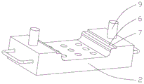
In the figure, 1, an upper die; 2. a lower die; 3. a stone pipe clamping piece; 31. a base plate; 32. a side plate; 33. mounting holes; 34. transition fillets; 4. a convex portion; 5. a recess; 6. positioning the platform; 7. positioning the surface; 8. a stone tube clamping piece blank; 9. a guide post; 10. a guide hole; 11. a connecting plate; 12. connecting columns; 13. a punch; 14. a blanking hole; 15. a material ejection hole; 16. a material ejecting device; 161. a material ejection block; 162. and ejecting the spring.
Detailed Description
The technical solution of the present invention will be clearly and completely described below with reference to specific embodiments. It is to be understood that the described embodiments are merely a few embodiments of the utility model, and not all embodiments. All other embodiments, which can be derived by a person skilled in the art from the embodiments of the present invention without any inventive step, are within the scope of the present invention.
Referring to fig. 1-4, the stone tube clamping piece processing and positioning device comprises an upper die 1 and a lower die 2, wherein the upper die 1 is provided with a convex part 4 matched with the shape of a stone tube clamping piece 3, the lower die 2 is provided with a concave part 5 matched with the upper die 1, a gap between the convex part 4 and the concave part 5 is a cavity formed by punching the stone tube clamping piece 3 when the upper die 1 and the lower die 2 are closed, two opposite sides of the concave part 5 are respectively provided with a positioning platform 6, the connecting surface of the positioning platform 6 and the upper end surface of the lower die 2 is a positioning surface 7, the distance between the positioning surfaces 7 of the two positioning platforms 6 is matched with the width of a stone tube clamping piece blank 8, before processing, the stone tube clamping piece blank 8 is placed on the positioning platform 6, two ends of the stone tube clamping piece blank 8 are abutted against the positioning surfaces 7, so as to realize positioning, the operation is convenient, the efficiency is high, and the stone tube blank 8 can not deviate in the process of closing the upper die 1 and the lower die 2, the processing precision is high.
Further, the fixed guide post 9 that is equipped with of up end of lower mould 2, go up mould 1 and be equipped with the guiding hole 10 relative with guide post 9 position, guide post 9 is the main guide part in the precision mould, has very big effect to improving the product precision, when the compound die divides the mould operation, goes up mould 1 along guide post 9 up-and-down motion, goes up the relative stability between mould 1 and the lower mould 2 better, is favorable to improving the machining precision of stone pipe clamping piece 3.
Further, it still is equipped with connecting plate 11 to go up the top of mould 1, connecting plate 11 is on a parallel with the up end of last mould 1, connecting plate 11 passes through spliced pole 12 and is connected with last mould 1, and connecting plate 11 is used for linking to each other with the press, and the pressure of exerting the press passes through spliced pole 12 and transmits last mould 1, goes up mould 1 downstream to with 2 compound dies of lower mould to realize stamping forming, in addition, be connected through spliced pole 12 between connecting plate 11 and the last mould 1, guarantee to have certain clearance between connecting plate 11 and the last mould 1, wear out from guiding hole 10 in the upper end of guide post 9 when being convenient for go up mould 1 along guide post 9 up-and-down motion, thereby the stroke of going up mould 1 motion has been increased.
Furthermore, the lower terminal surface of convex part 4 is equipped with the drift 13 relative with vacancy on the stone tube clamping piece 3, the up end of concave part 5 is equipped with the blanking hole 14 with drift 13 assorted, and drift 13 and blanking hole 14 have replaced cut-out press to process mounting hole 33 for curb plate 32 shaping and mounting hole 33 shaping go on in step, and machining efficiency is high, and only need once fix a position, and the locating standard is unified, and the machining precision is high.
Further, the lower end face of the convex portion 4 is further provided with an ejection hole 15, the blanking hole 14 and the ejection hole 15 are both provided with an ejection device 16, the ejection device 16 comprises an ejection block 161 and an ejection spring 162, the upper end of the ejection spring 162 is fixedly connected with the ejection block 161, the lower end of the ejection spring 162 is connected with the blanking hole 14 or the bottom of the ejection hole 15, the ejection device 16 located in the blanking hole 14 is used for ejecting waste materials punched by a punch during processing of the mounting hole 33, and the ejection device 16 located in the ejection hole 15 is used for ejecting the processed stone tube clamping piece 3 loose from the concave portion 5 of the lower die 2, so that demolding is facilitated, and the labor intensity of manual unloading is greatly reduced.
The process of processing and positioning the stone tube clamping piece 3 in the figure 1 comprises the following steps: firstly, connecting a connecting plate 11 at the upper end of an upper die 1 with a pressure head of a press machine, fixing a lower die 2 on a working platform of the press machine, and ensuring that a convex part 4 of the upper die 1 is opposite to a concave part of the lower die 2; then, placing the stone tube clamping piece blank 8 on the positioning platform 6, and enabling two ends of the stone tube clamping piece blank 8 to be abutted against the positioning surfaces 7 to achieve positioning of the stone tube clamping piece blank 8; and finally, starting the press machine, moving a pressure head of the press machine downwards, moving an upper die 1 downwards along a guide column 9 to be matched with a lower die 2, punching and forming a stone tube clamping piece blank 8 in a cavity formed between a convex part 4 and a concave part 5, simultaneously punching and forming a mounting hole 33 by a punch 13 at the lower end of the convex part 4, compressing an ejection block 161 into a hole by an ejection device 16 in a blanking hole 14 and an ejection hole 15 under the pressure of the upper die 1, separating the upper die 1 from the lower die 2 when the upper die 1 rises along with the press machine, moving the ejection block 161 in the ejection device 16 upwards under the elasticity of an ejection spring 162 at the moment, ejecting waste materials falling into the blanking hole 14 by the ejection block 161 in the blanking hole 14, and ejecting the processed stone tube clamping piece 3 from the concave part 5 of the lower die 2 by the ejection block 161 in the ejection hole 15 so as to facilitate die release.
Claims (5)
1. Stone pipe clamping piece processing positioner, including last mould (1) and lower mould (2), it is equipped with convex part (4) with stone pipe clamping piece (3) shape assorted to go up mould (1), lower mould (2) are equipped with and go up mould (1) assorted concave part (5), go up the space between convex part (4) and concave part (5) when mould (1) and lower mould (2) compound die and be stone pipe clamping piece (3) stamping forming die cavity, its characterized in that: concave part (5) both sides relatively all are equipped with positioning platform (6), positioning platform (6) are connected the face for locating surface (7) with the up end of lower mould (2), and the distance between locating surface (7) of two positioning platform (6) and the width phase-match of stone tube clamping piece blank (8).
2. The stone tube clamping piece processing and positioning device as claimed in claim 1, wherein: the upper end face of the lower die (2) is fixedly provided with a guide post (9), and the upper die (1) is provided with a guide hole (10) opposite to the guide post (9).
3. The stone tube clamping piece processing and positioning device as claimed in claim 1, wherein: go up the top of mould (1) and still be equipped with connecting plate (11), connecting plate (11) are on a parallel with the up end of mould (1), connecting plate (11) are connected with last mould (1) through spliced pole (12).
4. The stone tube clamping piece processing and positioning device as claimed in claim 1, wherein: the lower end face of the convex part (4) is provided with a punch (13) opposite to the upper vacant position of the stone tube clamping piece (3), and the upper end face of the concave part (5) is provided with a blanking hole (14) matched with the punch (13).
5. The stone tube clamping piece processing and positioning device as claimed in claim 4, wherein: the end surface still is equipped with material ejection hole (15) under convex part (4), all be equipped with liftout device (16) in blanking hole (14) and material ejection hole (15), liftout device (16) include ejector block (161) and liftout spring (162), the upper end and the ejector block (161) fixed connection of liftout spring (162), the lower extreme and the bottom of blanking hole (14) or material ejection hole (15) of liftout spring (162) are connected.
Priority Applications (1)
| Application Number | Priority Date | Filing Date | Title |
|---|---|---|---|
| CN202121977735.1U CN216095949U (en) | 2021-08-23 | 2021-08-23 | Stone pipe clamping piece processing and positioning device |
Applications Claiming Priority (1)
| Application Number | Priority Date | Filing Date | Title |
|---|---|---|---|
| CN202121977735.1U CN216095949U (en) | 2021-08-23 | 2021-08-23 | Stone pipe clamping piece processing and positioning device |
Publications (1)
| Publication Number | Publication Date |
|---|---|
| CN216095949U true CN216095949U (en) | 2022-03-22 |
Family
ID=80727710
Family Applications (1)
| Application Number | Title | Priority Date | Filing Date |
|---|---|---|---|
| CN202121977735.1U Active CN216095949U (en) | 2021-08-23 | 2021-08-23 | Stone pipe clamping piece processing and positioning device |
Country Status (1)
| Country | Link |
|---|---|
| CN (1) | CN216095949U (en) |
-
2021
- 2021-08-23 CN CN202121977735.1U patent/CN216095949U/en active Active
Similar Documents
| Publication | Publication Date | Title |
|---|---|---|
| CN201346595Y (en) | Composite cold-punching mould | |
| CN111822585B (en) | Automobile part stamping forming die capable of achieving accurate positioning | |
| CN115475879A (en) | Continuous stamping die of one shot forming contact pin and material area | |
| CN108015118A (en) | A kind of cold extrusion shaped mould structure of wire rod | |
| CN204182800U (en) | A kind of compound punching structure for punch level progressive die | |
| CN216095949U (en) | Stone pipe clamping piece processing and positioning device | |
| CN215697323U (en) | Pre-bending and pressing edge covering combined die for inner plate and outer plate of automobile covering part | |
| CN213997294U (en) | Automatic forming die for one-step bending multi-edge angle of large-scale plate | |
| CN213103986U (en) | Cold stamping forming device for manufacturing metal die | |
| CN213613666U (en) | Side shaping mechanism die for vehicle body cross beam reinforcement | |
| CN211941204U (en) | Cab interior stamping die | |
| CN211386516U (en) | Die structure for punching small holes on circumference from inside to outside | |
| CN208390781U (en) | The right angle auto parts and components continuous mould of side blow aperture apparatus and the application device | |
| CN208542820U (en) | The shape of a hoof parking brake balancing stand two-wire continuous stamping die for having automatic discharging function | |
| CN204892671U (en) | Compound mould of backing plate formal dress punching press | |
| CN219093351U (en) | Stamping die for precise panel bracket | |
| CN214639444U (en) | Automatic demolding and stamping die for automobile front floor | |
| CN216989399U (en) | Stamping equipment for post-cast strip supporting baffle | |
| CN219401951U (en) | Accurate stamping die is used in metalwork processing | |
| CN212857419U (en) | Full-circumference side forming die | |
| CN219724199U (en) | Die with adjustable cavity depth | |
| CN211135176U (en) | Quick-change punching structure of rolling die | |
| CN219052647U (en) | Continuous cutting belt folding die | |
| CN210523571U (en) | Back groove one-step forming die for processing channel steel | |
| CN113828683B (en) | Forming device and forming method for parts with holes |
Legal Events
| Date | Code | Title | Description |
|---|---|---|---|
| GR01 | Patent grant | ||
| GR01 | Patent grant |