CN216066171U - Stator core welding tool - Google Patents
Stator core welding tool Download PDFInfo
- Publication number
- CN216066171U CN216066171U CN202122269062.0U CN202122269062U CN216066171U CN 216066171 U CN216066171 U CN 216066171U CN 202122269062 U CN202122269062 U CN 202122269062U CN 216066171 U CN216066171 U CN 216066171U
- Authority
- CN
- China
- Prior art keywords
- mandrel
- pushing
- stator core
- expansion
- welding
- Prior art date
- Legal status (The legal status is an assumption and is not a legal conclusion. Google has not performed a legal analysis and makes no representation as to the accuracy of the status listed.)
- Active
Links
Images

Abstract
The utility model discloses a stator core welding tool which comprises a machining station arranged on a workbench, a welding base, a plurality of groove positioning strips, a plurality of expansion blocks, a mandrel bottom plate, a mandrel rod and a pushing mandrel, wherein the expansion blocks are sleeved on the corresponding groove positioning strips in a sliding manner along the radial direction of the axis of the machining station, the pushing mandrel is provided with a plurality of pushing teeth which radially extend outwards, the pushing teeth are matched with the expansion blocks in an inclined plane, each expansion block is provided with a pushing tooth groove, each pushing tooth is inserted into the corresponding pushing tooth groove, the stator core welding tool further comprises a plurality of mandrel anti-rotation inserts which extend upwards from the welding base and are uniformly distributed along the circumferential direction of the axis of the machining station, and a tensioning pressing plate fixed at the upper ends of the plurality of mandrel anti-rotation inserts, and each mandrel anti-rotation insert is positioned between two adjacent pushing teeth. The up-and-down movement of the mandrel is pushed, the expansion of the expansion block is converted into the expansion block to radially support the iron core lamination to realize concentricity, and the mandrel twisting in the pressing process of the upper pressing head is prevented by arranging a plurality of mandrel anti-rotation inserts.
Description
Technical Field
The utility model relates to a stator core welding tool.
Background
With the rapid development of new energy automobiles in China, the requirements on parts of the new energy automobiles are higher and higher, the quality requirements of stator cores are higher and higher, and on the premise of ensuring the production quality, how to improve the production efficiency is an urgent problem to be solved. The stator core is an integral structure formed by welding a plurality of laminated sheets, so that the quality of the stator core depends on the welding tool of the stator core to a great extent.
In the prior art, stator core welding frock also has a plurality of, like the high-speed motor stator silicon steel sheet welding frock mould of authorized bulletin number CN 210878333U, including dabber, core that rises, compression spring, taper sleeve and stator punching sheet group, the core activity that rises cup joints at the dabber, compression spring activity cup joints at the dabber, and compression spring is located the axle center hole of core that rises, the quantity of taper sleeve is two, two the taper sleeve is the activity cup joints upper and lower both ends at the dabber respectively, stator punching sheet group activity cup joints on the core that rises, the bell mouth has all been seted up to the upper and lower both sides of core that rises, and the bell mouth of core that rises and the axle center hole intercommunication of core that rises, the taper sleeve is pegged graft in the bell mouth of core that rises.
SUMMERY OF THE UTILITY MODEL
The utility model aims to provide a stator core welding tool.
In order to solve the technical problems, the utility model adopts the technical scheme that: a stator core welding tool is used for fixing a stator core and comprises a processing station arranged on a workbench, a welding base arranged on the processing station, a plurality of groove positioning strips which extend upwards from the welding base and are uniformly distributed along the circumferential direction of the axis of the processing station, a plurality of expansion blocks which are sleeved on the corresponding groove positioning strips along the radial sliding sleeve of the axis of the processing station, a mandrel base plate which can be arranged at the lower part of the welding base in a vertical sliding manner, a mandrel rod which is inserted in the middle of the welding base and is fixed on the mandrel base plate at the lower end part, and a pushing mandrel which is sleeved and fixed at the upper part of the mandrel rod, wherein the pushing mandrel is provided with a plurality of pushing teeth which extend outwards in the radial direction, the pushing teeth are matched with the expansion blocks in an inclined plane, and each expansion block is provided with a pushing tooth groove, each pushing tooth is inserted into the corresponding pushing tooth groove, a reset spring is arranged between the welding base and the mandrel base plate, the multi-mandrel anti-rotation insert which upwards extends out of the welding base and is uniformly distributed along the circumferential direction of the axis of a machining station and a tension pressing plate fixed at the upper end part of the multi-mandrel anti-rotation insert are further included, and each mandrel anti-rotation insert is located between two adjacent pushing teeth.
In some embodiments, a plurality of upper pressure head transmission keys are uniformly distributed along the circumferential direction of the axis of the processing station on an upper pressure head of the servo press above the stator core welding tool, the upper pressure head transmission keys are respectively located right above the corresponding push teeth, and the upper pressure head transmission keys abut against the push teeth when the upper pressure head transmission keys are pressed down.
In some embodiments, the lower surface of the upper pressure head is provided with a downward protruding edge used for pressing on the stator core during welding.
In some embodiments, a plurality of the swelling blocks enclose a hollow swelling sleeve having a cylindrical shape.
In some embodiments, the mandrel base plate is fixed on a discharging ejector rod which can enable the pushing mandrel to have upward movement trend after the pressure of the upper pressure head is relieved, and the discharging ejector rod is arranged on the processing station in a manner that the discharging ejector rod can slide up and down through a lifting mechanism.
In certain embodiments, the lifting mechanism is a pneumatic cylinder.
The scope of the present invention is not limited to the specific combinations of the above-described features, and other embodiments in which the above-described features or their equivalents are arbitrarily combined are also intended to be encompassed. For example, the above features and the technical features (but not limited to) having similar functions disclosed in the present application are mutually replaced to form the technical solution.
Due to the application of the technical scheme, compared with the prior art, the utility model has the following advantages: the utility model provides a stator core welding tool, which is characterized in that the up-and-down movement of a mandrel is pushed and converted into the expansion of an expansion block to radially support the core laminations to realize concentricity, the positions of the core laminations are relatively fixed, the welding can be realized when an upper pressure head above the core laminations is pressed downwards, the mandrel is prevented from twisting in the pressing process of the upper pressure head by arranging a plurality of mandrel anti-rotation insert blocks, the normal and smooth matching between the mandrel and the expansion block is ensured, the working stability is improved, the welding precision is improved, and the service life is prolonged.
Drawings
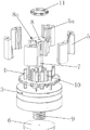
FIG. 1 is a plan view of a table with stator core welding tooling installed;
FIG. 2 is an exploded view of the tool;
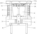
FIG. 3 is a cross-sectional view of the tooling;
wherein 1, a workbench; 2. a processing station; 3. welding a base; 4. a slot locating bar; 5. expanding blocks; 5a, pushing tooth grooves; 6. a mandrel base plate; 7. a core shaft lever; 8. pushing the mandrel; 8a, pushing teeth; 9. a return spring; 10. a core shaft anti-rotation insert; 11. tensioning the pressing plate; 12. an upper pressure head; 12a, an upper pressure head transmission key; 12b, pressing the edges; 13. and (4) discharging and ejecting the rod.
Detailed Description
As shown in the figures, in this embodiment, a stator core welding fixture is used for fixing a stator core, and includes a processing station 2 disposed on a workbench 1, the processing station 2 is rotatably disposed on the workbench 1, and further includes a welding base 3 mounted on the processing station 2, six slot positioning bars 4 extending upward from the welding base 3 and uniformly distributed along a circumferential direction of an axis of the processing station, six expansion blocks 5 slidably sleeved on the corresponding slot positioning bars 4 along a radial direction of the axis of the processing station, a mandrel base plate 6 slidably disposed at a lower portion of the welding base 3 up and down, a mandrel rod 7 inserted in a middle of the welding base 3 and having a lower end fixed on the mandrel base plate 6, a pushing mandrel 8 sleeved and fixed on an upper portion of the mandrel rod 7, the pushing mandrel 8 having six pushing teeth 8a extending outward in the radial direction, the push teeth 8a are matched with the expansion block 5 in an inclined plane, each expansion block 5 is provided with a push tooth groove 5a, each push tooth 8a is inserted into the corresponding push tooth groove 5a, a reset spring 9 enabling the push mandrel to have an upward movement trend is arranged between the welding base 3 and the mandrel base plate 6, the push tooth type anti-rotation mechanism further comprises six mandrel anti-rotation inserts 10 and tension pressing plates 11, wherein the six mandrel anti-rotation inserts 10 extend upwards from the welding base 3 and are uniformly distributed along the circumferential direction of the axis of a machining station, the tension pressing plates 11 are fixed at the upper end portions of the six mandrel anti-rotation inserts 10, and each mandrel anti-rotation insert 10 is located between every two adjacent push teeth 8 a. Prevent through setting up many dabbers and prevent changeing the dabber that inserts and prevent to push down the in-process at the upper pressure head and twist, guarantee that the cooperation between dabber and the piece that rises is normal smooth and easy, improve the stability of work, improve welded precision, increase life.
In this embodiment, six expansion blocks 5 enclose a cylindrical hollow expansion sleeve.
In this embodiment, the upper pressing head 12 of the servo press above the stator core welding tool is provided with six upper pressing head transmission keys 12a which are uniformly distributed along the circumferential direction of the axis of the machining station, the six upper pressing head transmission keys 12a are respectively located right above the corresponding pushing teeth 8a, and the upper pressing head transmission keys 12a abut against the pushing teeth 8a when the pressing is performed. And a blank holder 12b for pressing on the stator core during welding is extended downwards from the lower surface of the upper pressure head 12.
The mandrel bottom plate 6 is fixed on an unloading ejector rod 13 which enables the pushing mandrel 8 to have an upward movement trend after the pressure of the upper pressure head 12 is relieved, and the unloading ejector rod 13 is arranged on the processing station 2 in a manner of being capable of sliding up and down through a lifting mechanism. The lifting mechanism is a cylinder.
The iron core lamination is sleeved on the expansion sleeve in sequence, when the upper pressure head presses downwards, the upper pressure head transmission key on the upper pressure head drives the core shaft to move downwards, the push teeth on the core shaft are pushed to extrude the expansion block matched with the push teeth outwards to enable the expansion block to expand outwards along the radial direction, when the upper pressure head moves downwards to a certain position, the blank pressing edge of the upper pressure head is contacted with the upper surface of the iron core lamination, and at the moment, the upper pressure head stops moving downwards. In the process, the inner side walls of the plurality of iron core laminations and the outer side walls of the plurality of expansion blocks are in a contact state from a separation state, when the mandrel is pushed to drive the plurality of expansion blocks to continue to expand outwards, the inner side walls of the plurality of iron core laminations and the outer side walls of the plurality of expansion blocks are relatively static due to large tensioning force, the iron core laminations are axially compressed and radially tensioned, the fixation is firm, the inner circle expansion is neat, the inner holes are neat and free of staggered sheets, and meanwhile, the concentricity of the iron core laminations is guaranteed. Welding is then possible. The welded iron core notches are tidy, the inner circles are concentric, the laminating coefficient and the welding deformation of the iron core laminations can be guaranteed, and the subsequent welding quality of the iron core laminations is guaranteed.
After the welding is finished, the upper pressure head rises back, the mandrel is pushed to move upwards under the action of the reset spring, no acting force exists between the inner side walls of the multiple iron core laminations and the outer side walls of the expansion blocks, the welded stator iron core can be dismounted, and the next processing operation is continued.
The above embodiments are merely illustrative of the technical ideas and features of the present invention, and the purpose thereof is to enable those skilled in the art to understand the contents of the present invention and implement the present invention, and not to limit the protection scope of the present invention. All equivalent changes and modifications made according to the spirit of the present invention should be covered within the protection scope of the present invention.
Claims (6)
1. The utility model provides a stator core welding frock for fixed stator core, including setting up machining-position (2) on workstation (1), its characterized in that: the processing station (2) is rotatably arranged on the workbench (1), and further comprises a welding base (3) arranged on the processing station (2), a plurality of groove positioning strips (4) which extend upwards from the welding base (3) and are uniformly distributed along the circumferential direction of the axis of the processing station, a plurality of expansion blocks (5) which are sleeved on the corresponding groove positioning strips (4) along the radial sliding direction of the axis of the processing station, a mandrel base plate (6) which is arranged at the lower part of the welding base (3) in a vertical sliding manner, a mandrel rod (7) which is inserted in the middle of the welding base (3) and is fixed on the mandrel base plate (6) at the lower end part, and a pushing mandrel (8) which is sleeved and fixed on the upper part of the mandrel rod (7), wherein the pushing mandrel (8) is provided with a plurality of pushing teeth (8 a) which extend outwards in the radial direction, and the pushing teeth (8 a) are matched with the expansion blocks (5) in an inclined plane, and every it pushes away tooth's socket (5 a) to have on the expansion block (5), every it inserts correspondingly to push away tooth (8 a) push away in tooth's socket (5 a), welding base (3) with be provided with reset spring (9) between dabber bottom plate (6), still include by upwards stretch out and prevent changeing insert (10) along the many dabber of processing station axle center circumferencial direction evenly distributed on welding base (3), fix many tight clamp plate (11) that rises of dabber rotation-preventing insert (10) upper end, every dabber rotation-preventing insert (10) are located adjacent two it pushes away between tooth (8 a).
2. The stator core welding tool according to claim 1, characterized in that: be located on pressure head (12) on the servo press of stator core welding frock top have a plurality ofly along processing station axle center circumferencial direction evenly distributed go up pressure head drive key (12 a), it is a plurality of go up pressure head drive key (12 a) and be located correspondingly directly over push away tooth (8 a), during the pushing down go up pressure head drive key (12 a) and support push away on tooth (8 a).
3. The stator core welding tool according to claim 2, characterized in that: and a blank holder (12 b) used for pressing the stator core during welding is extended downwards from the lower surface of the upper pressure head (12).
4. The stator core welding tool according to claim 1, characterized in that: the expansion blocks (5) are enclosed to form a cylindrical hollow expansion sleeve.
5. The stator core welding tool according to claim 2, characterized in that: the mandrel bottom plate (6) is fixed on an unloading ejection rod (13) which can enable the pushing mandrel (8) to have an upward movement trend after the pressure of the upper pressure head (12) is relieved, and the unloading ejection rod (13) is arranged on the machining station (2) in a vertically sliding mode through a lifting mechanism.
6. The stator core welding tool according to claim 5, characterized in that: the lifting mechanism is a cylinder.
Priority Applications (1)
| Application Number | Priority Date | Filing Date | Title |
|---|---|---|---|
| CN202122269062.0U CN216066171U (en) | 2021-09-18 | 2021-09-18 | Stator core welding tool |
Applications Claiming Priority (1)
| Application Number | Priority Date | Filing Date | Title |
|---|---|---|---|
| CN202122269062.0U CN216066171U (en) | 2021-09-18 | 2021-09-18 | Stator core welding tool |
Publications (1)
| Publication Number | Publication Date |
|---|---|
| CN216066171U true CN216066171U (en) | 2022-03-18 |
Family
ID=80677410
Family Applications (1)
| Application Number | Title | Priority Date | Filing Date |
|---|---|---|---|
| CN202122269062.0U Active CN216066171U (en) | 2021-09-18 | 2021-09-18 | Stator core welding tool |
Country Status (1)
| Country | Link |
|---|---|
| CN (1) | CN216066171U (en) |
-
2021
- 2021-09-18 CN CN202122269062.0U patent/CN216066171U/en active Active
Similar Documents
| Publication | Publication Date | Title |
|---|---|---|
| CN216066171U (en) | Stator core welding tool | |
| CN108620497B (en) | Full-automatic plodder | |
| CN106849539B (en) | Simple stator core lamination die | |
| CN103990695A (en) | Blanking and bending compound die | |
| CN2640113Y (en) | Winding automobile generator stator iron core shaping device | |
| CN211183739U (en) | Block type stator core's straightness plastic frock that hangs down | |
| CN212442841U (en) | Aluminum alloy stamping flanging composite die | |
| CN213436934U (en) | Loading attachment for forging press based on intelligent control | |
| CN214639632U (en) | Combined quick-change socket hole stamping die | |
| CN207770592U (en) | A kind of production transfer line for automobile rear case | |
| CN213317202U (en) | Tensile mold processing of wheel spoke | |
| CN111390027A (en) | Numerical control machining rapid forming stamping die | |
| CN213613639U (en) | High-speed punching die for copper key | |
| CN211071498U (en) | High-efficient punch press mould | |
| CN217665725U (en) | Die for reducing burrs at punched part | |
| CN214978791U (en) | Welding positioning tool for scattered pieces of oil-cooled motor stator | |
| CN112828161A (en) | Combined quick-change socket hole stamping die | |
| CN218771681U (en) | Towards quick matched mould device of piece | |
| CN213671314U (en) | Forming die for panel of electric appliance cabinet | |
| CN214814240U (en) | Point riveting die for automobile exhaust end cone parts | |
| CN214235792U (en) | Novel side-push forming device for step circle wrapping | |
| CN220605725U (en) | Permanent magnet motor rotor riveting device | |
| CN214601378U (en) | Punching device of slurry pump end cover | |
| CN218693347U (en) | Round can forming die | |
| CN114713695B (en) | Stamping equipment for sheet metal parts |
Legal Events
| Date | Code | Title | Description |
|---|---|---|---|
| GR01 | Patent grant | ||
| GR01 | Patent grant |