CN213317202U - Tensile mold processing of wheel spoke - Google Patents
Tensile mold processing of wheel spoke Download PDFInfo
- Publication number
- CN213317202U CN213317202U CN202022008035.3U CN202022008035U CN213317202U CN 213317202 U CN213317202 U CN 213317202U CN 202022008035 U CN202022008035 U CN 202022008035U CN 213317202 U CN213317202 U CN 213317202U
- Authority
- CN
- China
- Prior art keywords
- die
- blanking
- mold core
- annular
- core
- Prior art date
- Legal status (The legal status is an assumption and is not a legal conclusion. Google has not performed a legal analysis and makes no representation as to the accuracy of the status listed.)
- Active
Links
Images


Abstract
The utility model provides a tensile mold processing of wheel spoke, include: feeding a mold frame; the upper die base is arranged on the upper die frame; the upper die pressing block is arranged on the upper die base and provided with an inserting channel; a jacking spring; the upper blanking punch seat is inserted into the inserting channel and is provided with a blanking punch block; the upper mold core comprises a first upper mold core and a second upper mold core; the lower die frame is provided with a central through hole; the lower die base is arranged on the lower die frame; the lower mold core comprises a first lower mold core and a second lower mold core; the lower blanking punch seat is inserted into the first lower die core and provided with blanking punches; the blank holder seat is arranged on the lower die seat; the blank holder is arranged on the upper surface of the blank holder seat; and the excircle blanking tool rest is arranged on the upper surface of the lower die frame. The processing die is designed to be of a split structure, so that flexibility and convenience are brought to debugging of the stretching die, the debugging efficiency of the spoke is improved, the processing and maintenance cost is reduced, and the positive effects of improving the stretching quality of the spoke and the fatigue resistance of the wheel are achieved.
Description
Technical Field
The utility model belongs to the technical field of automobile parts processing, specifically, relate to a tensile mold processing of wheel spoke.
Background
The wheel, which is an important part of a vehicle load, bears a vertical load, a lateral force, a driving (braking) torque, and various stresses generated during driving of the vehicle, is one of important safety parts of the vehicle, and thus, there are high demands on the design and manufacture of the wheel.
Spoke is a device for protecting wheel rim and spoke of vehicle wheel, and is characterized by that it is a pair of circular cover plates, the diameter of the cover plate is close to that of the wheel rim, the centre of the cover plate is equipped with a hole whose diameter is greater than that of the wheel rotating shaft, and the portion of the cover plate close to the edge is equipped with an orifice, and the edge of the cover plate is equipped with an annular wheel plate, and the curved surface of the wheel plate can be tightly attached to the curved surface of the wheel rim. According to the structure of the spoke, the wheel is divided into a spoke plate type and a spoke type, and the currently mainstream household saloon car adopts the spoke plate type spoke structure.
The wheel spoke drawing process is the most critical and important part in the spoke processing and production process, the spoke drawing die bears the distribution arrangement of materials in a spoke structure and determines the thinning and thickening amount in the material drawing process, the stress balance and the stress distribution of the spoke structure are influenced, and the molded surface structure of the drawing die core is a key factor influencing the strength of the spoke structure.
SUMMERY OF THE UTILITY MODEL
For solving the problem that exists, the utility model aims to provide a tensile mold processing of wheel spoke, mold processing will go up the mould core design components of a whole that can function independently structure to flexibility, convenience have been brought to the debugging of tensile mould, the debugging efficiency of spoke has been improved, has reduced the processing cost of maintenance of tensile mould in process of production simultaneously, and to the tensile quality that improves the spoke, the fatigue resistance that improves the wheel can play the positive role.
In order to achieve the above purpose, the technical scheme of the utility model is that:
a wheel spoke drawing processing die comprises: the upper die frame is horizontally placed, the upper surface of the upper die frame is connected with a sliding block of a machine tool, and the sliding block of the machine tool drives the upper die frame to ascend or descend; the upper die base is annular and is arranged on the lower surface of the upper die base; the upper die pressing block is slidably arranged on the inner side of the upper die base, an inserting channel penetrating through the upper die pressing block is formed in the middle of the lower surface of the upper die pressing block along the vertical direction, a plurality of pushing grooves are formed in the upper surface of the upper die pressing block positioned on the outer side of the inserting channel at intervals, and inserting grooves corresponding to the pushing grooves are formed in the lower surface of the upper die base; the upper die frame drives the upper die pressing block to eject or contract through the jacking spring; the upper blanking punch seat is vertically inserted into the insertion channel of the upper die pressing block, the upper end of the upper blanking punch seat is detachably connected with the upper die frame, the lower end of the upper blanking punch seat is provided with a blanking punch block, and the lower end of the blanking punch block extends out of the lower end of the insertion channel; the upper mold core comprises a horizontally arranged annular first upper mold core and an annular second upper mold core arranged on the lower surface of the first upper mold core, and the first upper mold core is arranged on the lower surface of the upper mold base and sleeved on the lower part of the outer wall of the upper mold pressing block; the lower die frame is positioned below the lower die frame, the lower die frame is horizontally arranged on a lower table-board of the machine tool, a central through hole penetrating through the lower die frame is formed in the middle of the upper surface of the lower die frame, and the central through hole corresponds to an inserting channel of the upper die pressing block; the lower die base is annular and is arranged in the middle of the upper surface of the lower die frame; the lower mold core comprises an annular first lower mold core horizontally arranged on the upper surface of the lower mold base and an annular second lower mold core sleeved on the outer wall of the first lower mold core, and central through holes of the first lower mold core, the lower mold base and the lower mold base are sequentially communicated to form a central channel; the lower blanking punch seat is inserted on the upper surface of the first lower mold core, and the upper surface of the lower blanking punch seat is provided with blanking punches which penetrate through the lower blanking punch seat and correspond to the blanking punch blocks; the blank holder seat is annular, is horizontally arranged on the upper surface of a lower die seat positioned on the outer side of the second lower die core, is vertically provided with a plurality of pushing through holes penetrating through the lower die frame at intervals corresponding to the upper surface of the lower die frame of the blank holder seat, is internally and vertically inserted with a push rod in each pushing through hole, the upper end of the push rod is connected with the bottom surface of the blank holder seat, and the lower end of the push rod is connected with a hydraulic ejector rod of the machine tool; the blank holder is annular and is arranged on the upper surface of the blank holder seat; the excircle blanking tool rest is vertically arranged on the upper surface of a lower die frame positioned outside the blank holder seat, a plurality of sections of excircle blanking tools are convexly arranged on the upper surface of the excircle blanking tool rest at intervals, the plurality of sections of excircle blanking tools are circumferentially arranged along the inner ring of the excircle blanking tool rest at intervals to form blanking tool rings, and the inner ring surface of each blanking tool ring corresponds to the outer ring surface of the second upper die core.
Furthermore, two ends of the lower surface of the upper die frame are provided with sleeve holes; and the upper surface of the lower die carrier is convexly provided with a guide post matched with the trepanning.
Furthermore, the upper end surface of the excircle blanking cutter and the upper end surface of the first lower mold core are positioned on the same horizontal plane; the hydraulic ejector rod of the machine tool drives the ejector rod to drive the blank holder seat to drive the blank holder to lift, and the upper end face of the blank holder, the upper end face of the excircle blanking cutter and the upper end face of the first lower mold core are located on the same horizontal plane to form support for spoke workpiece plates to be processed.
Furthermore, an annular guide groove is formed in the lower portion of the outer wall of the upper die pressing block along the circumferential direction of the upper die pressing block, so that a stepped structure of the outer wall of the upper die pressing block is formed; the inner surface of the inner ring of the first upper mold core is convexly provided with an annular bulge matched with the annular guide groove, and the annular bulge abuts against the outer wall of the annular guide groove; one surface of the annular bulge facing the annular guide groove is in a convex arc surface shape; and the lower part of the inner ring of the second upper mold core is recessed inwards to form a concave cambered surface.
Furthermore, the upper surface of the first lower mold core is a convex cambered surface.
Furthermore, the upper surface of the second lower mold core is a convex cambered surface; and the convex cambered surface of the upper surface of the second lower mold core corresponds to the concave cambered surface of the second upper mold core.
Furthermore, a clamping ring groove is formed in the lower surface of the first upper mold core; the upper surface of the second upper mold core is convexly provided with an annular positioning boss matched with the clamping ring groove; and the second upper die core is clamped with the clamping ring groove of the first upper die core through the positioning boss.
Furthermore, the shape of the excircle blanking cutter is strip-shaped, an arc-shaped groove is formed in the side surface of the excircle blanking cutter facing the inner annular surface of the excircle blanking cutter rest, and the radian of the arc-shaped groove corresponds to that of the inner annular surface of the excircle blanking cutter rest; a plurality of mounting holes are formed in the upper end face of the outer circle blanking cutter at intervals, and the outer circle blanking cutter is detachably arranged on the upper surface of the outer circle blanking cutter frame through the mounting holes.
Furthermore, the height of the middle part of the length direction of the upper end surface of the excircle blanking cutter is lower than the height of the two ends of the length direction of the upper end surface of the excircle blanking cutter; the height difference h between the middle part of the length direction of the upper end face of the excircle blanking cutter and the two ends of the length direction of the upper end face of the excircle blanking cutter is 3-5 mm.
The beneficial effects of the utility model reside in that:
the processing mould designs the upper mould core into a split structure, the upper mould core consists of the first upper mould core and the second upper mould core, so that flexibility and convenience are brought to the debugging of the drawing mould, the debugging efficiency of the spoke is improved, the processing and maintenance cost of the drawing mould in the production process is reduced, the drawing quality of the spoke is improved, and the anti-fatigue performance of the wheel is improved;
through the cooperation of excircle blanking sword, blank holder and second upper die core, form the shearing of spoke work piece panel excircle blanking, through the continuation of the lower surface of second upper die core push down and with the cooperation of second lower die core, form the tensile deformation of spoke work piece panel, the blanking punching block forms the blanking to the centre bore of spoke work piece panel with the cooperation of blanking seat down, processing process automation degree is high, spoke work piece panel shaping rate is high, machining efficiency is high.
Drawings
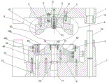
Fig. 1 is a schematic view of a mold opening structure of a mold for stretching and processing a wheel spoke according to an embodiment of the present invention;
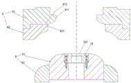
FIG. 2 is an enlarged schematic view of the structure at A in FIG. 1;
fig. 3 is a schematic view of a mold closing structure of a mold for stretching and processing a wheel spoke according to an embodiment of the present invention;
fig. 4 is a schematic structural view of an upper mold core and a lower mold core in the wheel spoke drawing processing mold according to the embodiment of the present invention;
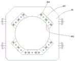
fig. 5 is a schematic structural view of an outer circle blanking knife and an outer circle blanking knife rest in a wheel spoke drawing processing die provided by an embodiment of the present invention;
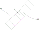
fig. 6 is a schematic structural view of an outer circle blanking knife in a wheel spoke drawing processing die provided by the embodiment of the utility model.
Detailed Description
The present invention will be described in detail with reference to the following embodiments. The following examples will assist those skilled in the art in further understanding the present invention, but are not intended to limit the invention in any way. It should be noted that various changes and modifications can be made by one skilled in the art without departing from the spirit of the invention. These all belong to the protection scope of the present invention.
Referring to fig. 1~6, a tensile mold processing of wheel spoke, include: the upper die carrier 1 is horizontally placed, the upper surface of the upper die carrier 1 is connected with a slide block (not shown) of a machine tool (not shown), and the slide block of the machine tool drives the upper die carrier 1 to ascend or descend; the upper die holder 2 is annular, and the upper die holder 2 is arranged on the lower surface of the upper die frame 1; the upper die pressing block 3 is slidably arranged on the inner side of the upper die base 2, an inserting channel 31 penetrating through the upper die pressing block 3 is formed in the middle of the lower surface of the upper die pressing block 3 along the vertical direction, a plurality of pushing grooves 32 are formed in the upper surface of the upper die pressing block 3 positioned on the outer side of the inserting channel 31 at intervals, and inserting grooves 11 corresponding to the pushing grooves 32 are formed in the lower surface of the upper die base 1; the upper die frame 1 drives the upper die pressing block 3 to eject or contract through the jacking springs 4; the upper blanking punch seat 5 is vertically inserted into the insertion channel 31 of the upper die pressing block 3, the upper end of the upper blanking punch seat 5 is detachably connected with the upper die frame 1, the lower end of the upper blanking punch seat 5 is provided with a blanking punch block 51, and the lower end of the blanking punch block 51 extends out of the lower end of the insertion channel 31; the upper mold core 6 comprises a horizontally arranged annular first upper mold core 61 and an annular second upper mold core 62 arranged on the lower surface of the first upper mold core 61, and the first upper mold core 61 is arranged on the lower surface of the upper mold base 2 and sleeved on the lower part of the outer wall of the upper mold swaging block 3; the lower die carrier 7 is positioned below the lower die carrier 1, the lower die carrier 7 is horizontally arranged on a lower table surface (not shown) of the machine tool, a central through hole 71 penetrating through the lower die carrier 7 is formed in the middle of the upper surface of the lower die carrier 7, and the central through hole 71 corresponds to the insertion channel 31 of the upper die pressing block 3; the lower die holder 8 is annular, and the lower die holder 8 is arranged in the middle of the upper surface of the lower die frame 7; the lower mold core 9 comprises an annular first lower mold core 91 horizontally arranged on the upper surface of the lower mold base 8 and an annular second lower mold core 92 sleeved on the outer wall of the first lower mold core 91, and the first lower mold core 91, the lower mold base 8 and the central through hole 71 of the lower mold frame 7 are sequentially communicated to form a central channel 70; the lower blanking punch seat 10 is inserted into the upper surface of the first lower mold core 91, and the upper surface of the lower blanking punch seat 10 is provided with a blanking punch hole 101 which penetrates through the lower blanking punch seat 10 and corresponds to the blanking punch block 51; the blank holder seat 20 is annular and horizontally arranged on the upper surface of a lower die seat 8 positioned on the outer side of a second lower die core 92, a plurality of pushing through holes 72 penetrating through the lower die frame 7 are vertically arranged on the upper surface of the lower die frame 7 corresponding to the lower surface of the blank holder seat 20 at intervals, the pushing through holes 72 are arranged at intervals along the circumferential direction of the blank holder seat 20, a push rod 73 is vertically inserted into each pushing through hole 72, the upper end of each push rod 73 is connected with the bottom surface of the blank holder seat 20, the lower end of each push rod 73 is connected with a hydraulic ejector rod (not shown) of the machine tool, and the hydraulic ejector rod of the machine tool drives the push rod 73 to drive the blank holder seat 20 to ascend or descend; the blank holder 30 is annular, and the blank holder 30 is arranged on the upper surface of the blank holder seat 20; the excircle blanking tool rest 40 is annular, the excircle blanking tool rest 40 is vertically arranged on the upper surface of the lower die holder 7 positioned outside the blank holder seat 20, a plurality of sections of excircle blanking tools 401 are convexly arranged on the upper surface of the excircle blanking tool rest 40 at intervals, the plurality of sections of excircle blanking tools 401 are circumferentially arranged along the inner ring of the excircle blanking tool rest 40 at intervals to form a blanking tool ring 402, and the inner ring surface of the blanking tool ring 402 corresponds to the outer ring surface of the second upper die core 62.
Furthermore, two ends of the lower surface of the upper die carrier 1 are provided with trepanning 12; the upper surface of the lower die carrier 7 is convexly provided with a guide post 74 matched with the trepanning 12.
Further, the upper end surface of the outer circle blanking knife 401 and the upper end surface of the first lower mold core 91 are located on the same horizontal plane; the hydraulic ejector rod of the machine tool drives the ejector rod 73 to drive the blank holder seat 20 to drive the blank holder 30 to ascend, and the upper end face of the blank holder 30, the upper end face of the excircle blanking cutter 401 and the upper end face of the first lower mold core 91 are located on the same horizontal plane to form a support for the spoke workpiece plate 100 to be processed.
Furthermore, an annular guide groove 33 is formed in the lower portion of the outer wall of the upper die pressing block 3 along the circumferential direction of the upper die pressing block 3, so that a stepped structure of the outer wall of the upper die pressing block 3 is formed; the inner surface of the inner ring of the first upper mold core 61 is convexly provided with an annular protrusion 611 matched with the annular guide groove 33, and the annular protrusion 611 abuts against the outer wall of the annular guide groove 33; the annular protrusion 611 faces the annular guide groove 33, and is shaped like a convex arc surface; the lower part of the inner ring of the second upper mold core 62 is concave inwards to form a concave arc surface.
Further, the upper surface of the first lower mold core 91 is a convex arc surface.
Further, the upper surface of the second lower mold core 92 is a convex arc surface; the convex arc surface of the upper surface of the second lower core 92 corresponds to the concave arc surface of the second upper core 62.
Further, a clamping ring groove 612 is formed in the lower surface of the first upper mold core 61; the upper surface of the second upper mold core 62 is convexly provided with an annular positioning boss 621 matched with the clamping ring groove 612; the second upper mold core 62 is clamped with the clamping ring groove 612 of the first upper mold core 61 through a positioning boss 621.
Further, the outer circle blanking cutter 401 is strip-shaped, an arc-shaped groove 403 is formed in the side surface of the outer circle blanking cutter 401, which faces the inner annular surface of the outer circle blanking cutter holder 40, and the radian of the arc-shaped groove 403 corresponds to the radian of the inner annular surface of the outer circle blanking cutter holder 40; a plurality of mounting holes 404 are formed in the upper end face of the outer circle blanking knife 401 at intervals, and the outer circle blanking knife 401 is detachably mounted on the upper surface of the outer circle blanking knife rest 40 through the mounting holes 404.
Further, the height of the middle part of the length direction of the upper end surface of the outer circle blanking knife 401 is lower than the height of the two ends of the length direction of the upper end surface of the outer circle blanking knife 401; the height difference h between the middle part of the length direction of the upper end face of the outer circle blanking knife 401 and the two ends of the length direction of the upper end face of the outer circle blanking knife 401 is 3-5 mm.
A tensile mold processing of wheel spoke's use as follows:
when the device is used, the upper die frame 1 is connected with the lower plane of a sliding block of a machine tool, the lower die frame 7 is connected with the lower table surface of the machine tool, the machine tool is started, the upper die frame 1 moves upwards to a die opening state (see figure 1) along with the sliding block, the upper die pressing block 3 is in an ejection state under the action of a jacking spring 4 (preferably a cylindrical spring), a hydraulic ejector rod of the machine tool ejects the blank holder seat 20 and the blank holder 30 through four ejector rods 73 until the upper surface of the blank holder 30 is flush with the upper surfaces of the excircle blanking knife rest 40 and the excircle blanking knife 401, and then the spoke workpiece plate 100 is placed on a supporting plane formed by the blank holder 30, the excircle blanking knife rest 40, the excircle blanking knife 401 and the first lower die core 91;
the slide block of the machine tool moves downwards, the upper die carrier 1 drives the upper die carrier 2, the first upper die core 61 and the second upper die core 62 to move downwards, the lower surface of the second upper die core 62 firstly contacts the spoke workpiece plate 100, the spoke workpiece plate 100 is tightly pressed on the upper surfaces of the blank holder 30 and the excircle blanking knife 401 and continues to move downwards, and the second upper die core 62 is matched with the arc-shaped groove 403 of the excircle blanking knife 401 to finish blanking and shearing of the excircle of the spoke workpiece plate 100;
the slide block of the machine tool continues to move downwards, the lower surface of the second upper mold core 62 continues to move downwards to the spoke workpiece plate 100 and compresses the blank holder 30, the blank holder seat 20, the ejector rod 73 and the hydraulic ejector rod of the machine tool to move downwards, the convex arc surface of the first lower mold core 91 is ejected to the spoke workpiece plate 100, the spoke workpiece plate 100 starts to be subjected to material stretching deformation, the outer circle of the spoke workpiece plate 100 contracts inwards along with the extension of the material, and meanwhile, the upper mold pressing block 3 starts to contact and press the spoke workpiece plate 100;
the slide block of the machine tool continues to move downwards, the upper die pressing block 3 compresses the jacking spring 4 to return upwards, the blanking punching block 51 extends out and contacts the central part of the spoke workpiece plate 100, the slide block of the machine tool continues to move downwards to drive the blanking punching block 51 to complete the blanking of a spoke central hole (not shown) of the spoke workpiece plate 100 in cooperation with the blanking punching hole 101 of the blanking punching seat 10, then the spoke workpiece plate 100 is completely pressed in a cavity (see figure 3) formed after the upper die core 6 and the lower die core 9 are closed, and the procedures of blanking stretching and punching the central hole of the spoke workpiece plate 100 are completed.
The processing mould designs the upper mould core 6 into a split structure, the upper mould core 6 consists of a first upper mould core 61 and a second upper mould core 62, so that flexibility and convenience are brought to the debugging of the drawing mould, the debugging efficiency of the spoke is improved, the processing and maintenance cost of the drawing mould in the production process is reduced, the drawing quality of the spoke is improved, and the anti-fatigue performance of the wheel is improved;
through the cooperation of excircle blanking sword 401, blank holder 30 and second upper die core 62, form the shearing of spoke work piece panel 100 excircle blanking, through the continuation of the lower surface of second upper die core 62 push down and with the cooperation of second lower die core 92, form the tensile deformation to spoke work piece panel 100, blanking punching block 51 forms the blanking to spoke work piece panel 100's spoke centre bore with the cooperation of falling material towards seat 10, the degree of automation of processing process is high, spoke work piece panel shaping rate is high, machining efficiency is high.
It should be noted that the above embodiments are only used for illustrating the technical solutions of the present invention and are not limited. Although the present invention has been described in detail with reference to the preferred embodiments, those skilled in the art will appreciate that various modifications and equivalent arrangements can be made without departing from the scope of the present invention, which is intended to be covered by the appended claims.
Claims (9)
1. The utility model provides a tensile mold processing of wheel spoke which characterized in that includes:
the upper die frame is horizontally placed, the upper surface of the upper die frame is connected with a sliding block of a machine tool, and the sliding block of the machine tool drives the upper die frame to ascend or descend;
the upper die base is annular and is arranged on the lower surface of the upper die base;
the upper die pressing block is slidably arranged on the inner side of the upper die base, an inserting channel penetrating through the upper die pressing block is formed in the middle of the lower surface of the upper die pressing block along the vertical direction, a plurality of pushing grooves are formed in the upper surface of the upper die pressing block positioned on the outer side of the inserting channel at intervals, and inserting grooves corresponding to the pushing grooves are formed in the lower surface of the upper die base;
the upper die frame drives the upper die pressing block to eject or contract through the jacking spring;
the upper blanking punch seat is vertically inserted into the insertion channel of the upper die pressing block, the upper end of the upper blanking punch seat is detachably connected with the upper die frame, the lower end of the upper blanking punch seat is provided with a blanking punch block, and the lower end of the blanking punch block extends out of the lower end of the insertion channel;
the upper mold core comprises a horizontally arranged annular first upper mold core and an annular second upper mold core arranged on the lower surface of the first upper mold core, and the first upper mold core is arranged on the lower surface of the upper mold base and sleeved on the lower part of the outer wall of the upper mold pressing block;
the lower die frame is positioned below the lower die frame, the lower die frame is horizontally arranged on a lower table-board of the machine tool, a central through hole penetrating through the lower die frame is formed in the middle of the upper surface of the lower die frame, and the central through hole corresponds to an inserting channel of the upper die pressing block;
the lower die base is annular and is arranged in the middle of the upper surface of the lower die frame;
the lower mold core comprises an annular first lower mold core horizontally arranged on the upper surface of the lower mold base and an annular second lower mold core sleeved on the outer wall of the first lower mold core, and central through holes of the first lower mold core, the lower mold base and the lower mold base are sequentially communicated to form a central channel;
the lower blanking punch seat is inserted on the upper surface of the first lower mold core, and the upper surface of the lower blanking punch seat is provided with blanking punches which penetrate through the lower blanking punch seat and correspond to the blanking punch blocks;
the blank holder seat is annular, is horizontally arranged on the upper surface of a lower die seat positioned on the outer side of the second lower die core, is vertically provided with a plurality of pushing through holes penetrating through the lower die frame at intervals corresponding to the upper surface of the lower die frame of the blank holder seat, is internally and vertically inserted with a push rod in each pushing through hole, the upper end of the push rod is connected with the bottom surface of the blank holder seat, and the lower end of the push rod is connected with a hydraulic ejector rod of the machine tool;
the blank holder is annular and is arranged on the upper surface of the blank holder seat;
the excircle blanking tool rest is vertically arranged on the upper surface of a lower die frame positioned outside the blank holder seat, a plurality of sections of excircle blanking tools are convexly arranged on the upper surface of the excircle blanking tool rest at intervals, the plurality of sections of excircle blanking tools are circumferentially arranged along the inner ring of the excircle blanking tool rest at intervals to form blanking tool rings, and the inner ring surface of each blanking tool ring corresponds to the outer ring surface of the second upper die core.
2. The drawing processing die for the wheel spoke according to claim 1, wherein sleeve holes are formed in two ends of the lower surface of the upper die frame;
and the upper surface of the lower die carrier is convexly provided with a guide post matched with the trepanning.
3. The drawing processing die for the wheel spoke according to claim 1, wherein the upper end surface of the outer circle blanking cutter and the upper end surface of the first lower die core are positioned on the same horizontal plane;
the hydraulic ejector rod of the machine tool drives the ejector rod to drive the blank holder seat to drive the blank holder to lift, and the upper end face of the blank holder, the upper end face of the excircle blanking cutter and the upper end face of the first lower mold core are located on the same horizontal plane to form support for spoke workpiece plates to be processed.
4. The drawing processing die for the wheel spoke according to claim 1, wherein an annular guide groove is formed in the lower portion of the outer wall of the upper die pressing block along the circumferential direction of the upper die pressing block to form a stepped structure of the outer wall of the upper die pressing block;
the inner surface of the inner ring of the first upper mold core is convexly provided with an annular bulge matched with the annular guide groove, and the annular bulge abuts against the outer wall of the annular guide groove;
one surface of the annular bulge facing the annular guide groove is in a convex arc surface shape;
and the lower part of the inner ring of the second upper mold core is recessed inwards to form a concave cambered surface.
5. A wheel disc stretching machining die as claimed in claim 1, wherein the upper surface of the first lower die core is a convex arc surface.
6. The drawing processing die for the wheel spoke according to claim 1, wherein the upper surface of the second lower die core is a convex arc surface;
and the convex cambered surface of the upper surface of the second lower mold core corresponds to the concave cambered surface of the second upper mold core.
7. The drawing processing die for the wheel spoke according to the claim 1 or 4, wherein a clamping ring groove is formed in the lower surface of the first upper die core;
the upper surface of the second upper mold core is convexly provided with an annular positioning boss matched with the clamping ring groove;
and the second upper die core is clamped with the clamping ring groove of the first upper die core through the positioning boss.
8. The drawing and processing die for the wheel spoke according to claim 1, wherein the outer circle blanking cutter is in a strip shape, an arc-shaped groove is formed in the side surface of the outer circle blanking cutter, which faces the inner ring surface of the outer circle blanking cutter rest, and the radian of the arc-shaped groove corresponds to that of the inner ring surface of the outer circle blanking cutter rest;
a plurality of mounting holes are formed in the upper end face of the outer circle blanking cutter at intervals, and the outer circle blanking cutter is detachably arranged on the upper surface of the outer circle blanking cutter frame through the mounting holes.
9. The drawing and processing die for the wheel spoke according to the claim 1, 3 or 8, wherein the height of the middle part of the length direction of the upper end surface of the outer circle blanking cutter is lower than the height of the two ends of the length direction of the upper end surface of the outer circle blanking cutter;
the height difference h between the middle part of the length direction of the upper end face of the excircle blanking cutter and the two ends of the length direction of the upper end face of the excircle blanking cutter is 3-5 mm.
Priority Applications (1)
| Application Number | Priority Date | Filing Date | Title |
|---|---|---|---|
| CN202022008035.3U CN213317202U (en) | 2020-09-15 | 2020-09-15 | Tensile mold processing of wheel spoke |
Applications Claiming Priority (1)
| Application Number | Priority Date | Filing Date | Title |
|---|---|---|---|
| CN202022008035.3U CN213317202U (en) | 2020-09-15 | 2020-09-15 | Tensile mold processing of wheel spoke |
Publications (1)
| Publication Number | Publication Date |
|---|---|
| CN213317202U true CN213317202U (en) | 2021-06-01 |
Family
ID=76063482
Family Applications (1)
| Application Number | Title | Priority Date | Filing Date |
|---|---|---|---|
| CN202022008035.3U Active CN213317202U (en) | 2020-09-15 | 2020-09-15 | Tensile mold processing of wheel spoke |
Country Status (1)
| Country | Link |
|---|---|
| CN (1) | CN213317202U (en) |
-
2020
- 2020-09-15 CN CN202022008035.3U patent/CN213317202U/en active Active
Similar Documents
| Publication | Publication Date | Title |
|---|---|---|
| CN205147022U (en) | Rear axle locking packing ring dashes 24 casement utensils for two steps | |
| CN111250590A (en) | Stamping die | |
| CN112170696B (en) | Stamping forming die for automobile seat side plate waist support bracket | |
| CN212857587U (en) | Forging die | |
| CN213317202U (en) | Tensile mold processing of wheel spoke | |
| CN210877129U (en) | One-time simultaneous blanking-punching manufacturing two-piece composite die for automobile rear axle refueling plug seat | |
| CN111097837A (en) | Reverse punching die for circular tube part | |
| CN217798429U (en) | Blanking, drawing and punching composite die and equipment using same | |
| CN216324431U (en) | Multi-station stamping device for producing connector part of double-clutch transmission | |
| CN214442191U (en) | Pipe joint limiting ring progressive die structure | |
| CN210280380U (en) | Machining die for balance block of automobile engine | |
| CN207479325U (en) | A kind of holder for tapered roller bearing integration makes assembling die | |
| CN211276390U (en) | Outer lane multistation integrative structure of repairing | |
| CN214022993U (en) | Skylight reinforcing plate flanging reshaping, flanging, punching and trimming composite die for automobile | |
| CN215467411U (en) | Rotary cutting die for sleeve for automobile chassis | |
| CN219520197U (en) | Punching and chamfering integrated processing die | |
| CN219703231U (en) | Continuous stamping die of secondary drawing | |
| CN214161117U (en) | Mould of blade circle on area material | |
| CN213256583U (en) | Stamping die for shaft sleeve punching | |
| CN214023058U (en) | High-strength trimming, punching and die assembling die for vehicle door A column | |
| CN212469408U (en) | Trimming die for automobile door hinge | |
| CN219724307U (en) | Composite die for machining wheel spokes | |
| CN107413946B (en) | Retainer integrated manufacturing combined die for tapered roller bearing | |
| CN109013832A (en) | A kind of auto parts blanking die being decorated structure | |
| CN216175880U (en) | Lamp holder blanking connection punching die |
Legal Events
| Date | Code | Title | Description |
|---|---|---|---|
| GR01 | Patent grant | ||
| GR01 | Patent grant |