CN216050821U - Solid phase sediment sample collection device - Google Patents
Solid phase sediment sample collection device Download PDFInfo
- Publication number
- CN216050821U CN216050821U CN202122164047.XU CN202122164047U CN216050821U CN 216050821 U CN216050821 U CN 216050821U CN 202122164047 U CN202122164047 U CN 202122164047U CN 216050821 U CN216050821 U CN 216050821U
- Authority
- CN
- China
- Prior art keywords
- inner core
- outer steel
- handle
- solid phase
- drill bit
- Prior art date
- Legal status (The legal status is an assumption and is not a legal conclusion. Google has not performed a legal analysis and makes no representation as to the accuracy of the status listed.)
- Active
Links
Images


Abstract
The utility model discloses a solid-phase sediment sample collecting device, which comprises an outer steel sleeve, a bulldozing handle, an operating handle and a sampling drill bit, wherein an inner core rod column is arranged in the outer steel sleeve, and the lower end of the inner core rod column penetrates through a reserved guide hole in the top of the sampling drill bit and then is connected with a bulldozing piston; bulldoze the handle and articulate on the outer wall of outer steel bushing, and the fork department of bulldozing the handle front portion sets up the connecting axle, and the middle part of connecting axle is provided with the push ram, supports on the inner core post after the preformed hole on the outer steel bushing is run through to the lower extreme of push ram, and the inner core post is provided with a plurality of and the inconsistent complex recess of push ram along length direction. The detachable type portable multifunctional folding chair integrally adopts a detachable mode, all the parts are firmly, simply and labor-saving in connection, the single part occupies a small space after being disassembled, and the portable multifunctional folding chair is convenient to store and carry and does not need other auxiliary tools; the bulldozing structure utilizes the lever principle, can be convenient laborsaving push out the drill bit with the sample whole fast, keep sample whole form complete.
Description
Technical Field
The utility model relates to the field of sample collection, in particular to a solid-phase sediment sample collection device.
Background
A solid phase sediment (including but not limited to solid phase/semi-solid phase sediment in nature such as soil, river flood sediment, ice core and the like) sample collection device, which can be widely applied to matrix collection of soil standard sample preparation; ecological environment prevention and treatment, and sampling of current situation investigation of soil and underground water restoration projects; the method is applied to the fields of agricultural chemical analysis, soil/mine ecological restoration, geochemical cycle analysis and the like, and the collection work of solid phase/semi-solid phase sediment samples in the related research fields.
Currently, solid phase sediments (including but not limited to solid/semi-solid phase sediments in nature such as soil, river flood sediments, ice core, etc.) are collected using a tool known in the industry as "earth boring". The conventional manner of use of the tool is as follows: the method comprises the steps of determining sampling points, vertically placing the earth drill with the surface of the sediment, utilizing the weight of an operator to press the earth drill downwards or using an object to hammer the top of the earth drill to enable the earth drill to enter the sediment, utilizing manpower to twist the earth drill after the earth drill enters a certain depth to enable the contact surface of the earth drill and the sediment to be loosened, and then manually extracting the earth drill from the sediment.
The drill bit that uses adopts half open architecture more, and the benefit of half open architecture is: the solid phase sediment is convenient to take out from the drill bit, and the defects are that: the sample may be polluted among different layers in the sampling process; when the solid phase deposit is removed from the drill bit, the morphology of the sample is destroyed.
SUMMERY OF THE UTILITY MODEL
Based on the above problems, the present invention aims to provide a solid phase sediment sample collection device, which adopts the following technical scheme:
the utility model provides a solid-phase sediment sample collecting device which comprises an outer steel sleeve and a bulldozing handle, wherein the top of the outer steel sleeve is provided with an operating handle, the bottom of the outer steel sleeve is provided with a sampling drill bit, an inner core rod column is arranged in the outer steel sleeve, the upper end of the inner core rod column is connected with the outer steel sleeve through an inner core fixing lock, and the lower end of the inner core rod column penetrates through a reserved guide hole in the top of the sampling drill bit and then is connected with a bulldozing piston in the sampling drill bit;
bulldoze the handle and be the Y font, two branches of the front portion of bulldozing the handle articulate on the outer wall of outer steel bushing, the fork department of bulldozing the handle front portion sets up the connecting axle, the tip of connecting axle articulates on two branches of bulldozing the handle front portion, the middle part of connecting axle is provided with the feed ram, the feed ram upper end with the connecting axle is connected, and the lower extreme runs through support after the preformed hole on the outer steel bushing on the inner core pole post, the inner core pole post along length direction on be provided with a plurality of with the inconsistent complex recess of feed ram.
Further, operating handle includes the handle, the middle part of handle is provided with the roof, the bottom surface joint of roof has the bottom plate, the bottom plate is fixed the top surface of outer steel bushing.
Furthermore, rubber handles are arranged at two ends of the handle.
Furthermore, the top plate and the bottom plate are connected together through a dovetail-shaped clamping structure.
Furthermore, the sampling drill bit is of a thin-walled cylinder structure, and a graduated scale is arranged on the outer wall of the sampling drill bit.
Furthermore, an elongated observation hole is formed beside the graduated scale.
Furthermore, the bottom of the outer steel sleeve is provided with a connecting cap, the top surface of the connecting cap is fixedly connected with the outer steel sleeve, and the connecting cap is connected with the outer wall of the top of the sampling drill bit through threads.
Furthermore, the cross section of the inner core rod column is polygonal.
Furthermore, a rib plate is arranged at the joint of the outer steel sleeve and the connecting cap.
Furthermore, the inner core fixing lock is a bolt, and a threaded end of the inner core fixing lock penetrates through a preformed hole in the outer steel sleeve and then is in threaded connection with the inner core rod column.
Compared with the prior art, the utility model has the beneficial technical effects that:
the detachable type portable multifunctional folding chair integrally adopts a detachable mode, all the parts are firmly, simply and labor-saving in connection, the single part occupies a small space after being disassembled, and the portable multifunctional folding chair is convenient to store and carry and does not need other auxiliary tools; the bulldozing structure utilizes a lever principle, so that the sampled product can be conveniently and rapidly pushed out of the drill bit in a labor-saving manner, and the overall shape of the sample is complete; the utility model can be widely applied to the matrix collection for preparing the soil standard sample; ecological environment prevention and treatment, and sampling of current situation investigation of soil and underground water restoration projects; the method is applied to the fields of agricultural chemical analysis, soil/mine ecological restoration, geochemical cycle analysis and the like, and the collection work of solid phase/semi-solid phase sediment samples in the related research fields.
Drawings
The utility model is further illustrated in the following description with reference to the drawings.
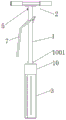
FIG. 1 is a schematic front view of a solid phase deposit sample collection device according to an embodiment of the present invention;
FIG. 2 is a schematic cross-sectional view of a solid phase deposit sample collection assembly according to an embodiment of the present invention;
FIG. 3 is a schematic view of the interference fit between the push rod and the inner core rod string according to the embodiment of the present invention;
FIG. 4 is a schematic view of the structure of a bulldozer handle according to the embodiment of the present invention;
FIG. 5 is a schematic structural view of an inner core post in an embodiment of the present invention;
FIG. 6 is a schematic structural view of an operating handle in an embodiment of the present invention;
FIG. 7 is a schematic view of the connection cap to the sampling drill according to an embodiment of the present invention;
FIG. 8 is a schematic structural diagram of a sampling drill according to an embodiment of the present invention.
Description of reference numerals: 1. an outer steel jacket; 2. an operating handle; 201. a handle; 202. a top plate; 203. a base plate; 204. a rubber handle; 3. a sampling drill bit; 301. a graduated scale; 302. an observation hole; 4. an inner core post; 401. a groove; 5. locking the inner core; 6. a dozing piston; 7. a bulldozer handle; 8. a connecting shaft; 9. a push rod; 10. a connecting cap; 11001. a rib plate;
Detailed Description
In order to make the technical solutions of the present invention better understood by those skilled in the art, the present invention will be further described in detail with reference to the accompanying drawings and the detailed description.
As shown in fig. 1 to 8, the present embodiment discloses a solid phase sediment sample collecting device, which comprises an outer steel sleeve 1, an operating handle 2 and a sampling drill bit 3. The operating handle 2 is positioned at the top of the outer steel sleeve 1, and the sampling drill bit 3 is positioned at the bottom of the outer steel sleeve 1. The sampling drill bit 3 is of a thin-walled cylinder structure, and a graduated scale 301 is arranged on the outer wall of the sampling drill bit 3. An elongated viewing aperture 302 is provided alongside the scale.
An inner core rod column 4 is arranged in the outer steel sleeve 1, the upper end of the inner core rod column 4 is connected with the outer steel sleeve 1 through an inner core fixing lock 5, and the lower end of the inner core rod column 4 penetrates through a reserved guide hole in the top of the sampling drill bit 3 and then is connected with a bulldozing piston 6 in the sampling drill bit 3.
Be connected with bulldozing handle 7 on the outer steel bushing 1, the utensil is said, bulldozing handle 7 is the Y font, two spinal branch poles of the front portion of bulldozing handle 7 articulate on the outer wall of outer steel bushing 1, the anterior fork mouth department of bulldozing handle 7 sets up connecting axle 8, the tip of connecting axle 8 articulates on two spinal branch poles of bulldozing handle 7 front portion, the middle part of connecting axle 8 is provided with push rod 9, push rod 9 upper end is connected with connecting axle 8, the lower extreme runs through to support after the preformed hole on the outer steel bushing 1 on at the inner core pole post 4, inner core pole post 4 is provided with a plurality ofly along length direction with push rod 9 inconsistent complex recess 401.
When the bulldozing handle 7 is lifted, the pushing rod 9 moves downwards under the action of the lever principle to push the inner core rod column 4 to move downwards, and then the inner core rod column 4 drives the lower bulldozing piston 6 to move downwards to push a sample out of the sampling drill bit 3.
Conveniently carry for this collection system, easily accomodate the easy, in this embodiment, outer steel bushing 1, operating handle 2 and sample drill bit 3 design into easy dismouting structure. Specifically, the method comprises the following steps:
as shown in fig. 6, the operating handle 2 includes a handle 201, a top plate 202 welded to the middle of the handle 201, a bottom plate 203 clamped to the bottom surface of the top plate 202, and the bottom plate 203 welded to the top surface of the outer steel sleeve 1. When in use, the top plate 202 is transversely clamped on the bottom plate 203. In order to facilitate the operation of the tester, rubber handles 204 are arranged at both ends of the handle 201.
In this embodiment, the top plate 202 and the bottom plate 203 are connected together by a dovetail type snap structure.
As shown in fig. 7, a connecting cap 10 is welded to the bottom of the outer steel jacket 1, the top surface of the connecting cap 10 is welded to the outer steel jacket 1, and the connecting cap 10 is connected to the outer wall of the top of the sampling drill 3 through threads.
When the sample, for preventing that sample drill bit 3 is connected not hard up with connecting cap 10, the cross section design of inner core post 4 is the polygon, and the guiding hole of mutually supporting with inner core post 4 is all seted up at the top of connecting cap 10 and sample drill bit 3. In this embodiment, the inner leg 4 is rectangular.
In order to improve the connection strength between the sampling drill bit 3 and the connection cap 10, a rib plate 1001 is welded at the joint between the outer steel sleeve 1 and the connection cap 10.
In a possible implementation manner, in the present embodiment, the inner core fixing lock 5 is a bolt, and the threaded end of the inner core fixing lock 5 penetrates through the reserved hole on the outer steel sleeve 1 and then is in threaded connection with the inner core rod column 4.
The action process of the utility model is as follows:
first, the outer steel jacket 1, the operating handle 2 and the sampling drill 3 are assembled together, and then the inner core rod 4 is reversely inserted into the outer steel jacket 1 through the sampling drill 3 and the inner core rod 4 is fixed by the inner core fixing lock 5.
After the combination is finished, the sampling drill bit 3 is vertically inserted into the sampling point position by utilizing the thrust of the human body. When the drill bit goes deep into the corresponding depth of the graduated scale, the operating handle 2 is twisted to drive the sampling drill bit 3 to rotate and pull out from the sampling point.
After the sampling drill bit is pulled out, the inner core fixing lock 5 is opened, namely the bolt is loosened, when the bulldozing handle 7 is lifted, the pushing rod 9 moves downwards under the action of the lever principle to push the inner core rod column 4 to move downwards, and then the inner core rod column 4 drives the lower bulldozing piston 6 to move downwards, so that a sample is pushed out of the sampling drill bit 3, and the whole sampling process is completed.
After sampling is completed, the whole device is disassembled, the drill bit is wiped, and all the components are placed in the equipment box.
The above-described embodiments are merely illustrative of the preferred embodiments of the present invention, and do not limit the scope of the present invention, and various modifications and improvements of the technical solutions of the present invention can be made by those skilled in the art without departing from the spirit of the present invention, and the technical solutions of the present invention are within the scope of the present invention defined by the claims.
Claims (10)
1. A solid phase deposit sample collection device, comprising:
the device comprises an outer steel sleeve (1), wherein an operating handle (2) is arranged at the top of the outer steel sleeve (1), a sampling drill bit (3) is arranged at the bottom of the outer steel sleeve (1), an inner core rod column (4) is arranged in the outer steel sleeve (1), the upper end of the inner core rod column (4) is connected with the outer steel sleeve (1) through an inner core fixing lock (5), and the lower end of the inner core rod column (4) penetrates through a reserved guide hole at the top of the sampling drill bit (3) and then is connected with a bulldozing piston (6) inside the sampling drill bit (3);
bulldoze handle (7), bulldoze handle (7) are the Y font, the two anterior branches of bulldozing handle (7) articulate on the outer wall of outer steel bushing (1), the fork department of bulldozing handle (7) front portion sets up connecting axle (8), the tip of connecting axle (8) articulates on the two anterior branches of bulldozing handle (7), the middle part of connecting axle (8) is provided with push rod (9), the upper end of push rod (9) with connecting axle (8) are connected, and the lower extreme runs through support behind the preformed hole on outer steel bushing (1) on inner core rod post (4), inner core rod post (4) along length direction on be provided with a plurality of with push rod (9) inconsistent complex recess (401).
2. The solid phase deposit sample collection device of claim 1, wherein: the operating handle (2) comprises a handle (201), a top plate (202) is arranged in the middle of the handle (201), a bottom plate (203) is clamped on the bottom surface of the top plate (202), and the bottom plate (203) is fixed on the top surface of the outer steel sleeve (1).
3. The solid phase deposit sample collection device of claim 2, wherein: two ends of the handle (201) are provided with rubber handles (204).
4. The solid phase deposit sample collection device of claim 2, wherein: the top plate (202) and the bottom plate (203) are connected together through a dovetail-shaped clamping structure.
5. The solid phase deposit sample collection device of claim 1, wherein: the sampling drill bit (3) is of a thin-walled cylinder structure, and a graduated scale (301) is arranged on the outer wall of the sampling drill bit (3).
6. The solid phase deposit sample collection device of claim 5, wherein: an elongated observation hole (302) is arranged beside the scale ().
7. The solid phase deposit sample collection device of claim 1, wherein: the bottom of the outer steel sleeve (1) is provided with a connecting cap (10), the top surface of the connecting cap (10) is fixedly connected with the outer steel sleeve (1), and the connecting cap (10) is connected with the outer wall of the top of the sampling drill bit (3) through threads.
8. The solid phase deposit sample collection device of claim 7, wherein: the cross section of the inner core rod column (4) is polygonal.
9. The solid phase deposit sample collection device of claim 7, wherein: and a rib plate (1001) is arranged at the joint of the outer steel sleeve (1) and the connecting cap (10).
10. The solid phase deposit sample collection device of claim 1, wherein: the inner core fixing lock (5) is a bolt, and the threaded end of the inner core fixing lock (5) penetrates through a preformed hole in the outer steel sleeve (1) and then is in threaded connection with the inner core rod column (4).
Priority Applications (1)
| Application Number | Priority Date | Filing Date | Title |
|---|---|---|---|
| CN202122164047.XU CN216050821U (en) | 2021-09-08 | 2021-09-08 | Solid phase sediment sample collection device |
Applications Claiming Priority (1)
| Application Number | Priority Date | Filing Date | Title |
|---|---|---|---|
| CN202122164047.XU CN216050821U (en) | 2021-09-08 | 2021-09-08 | Solid phase sediment sample collection device |
Publications (1)
| Publication Number | Publication Date |
|---|---|
| CN216050821U true CN216050821U (en) | 2022-03-15 |
Family
ID=80536108
Family Applications (1)
| Application Number | Title | Priority Date | Filing Date |
|---|---|---|---|
| CN202122164047.XU Active CN216050821U (en) | 2021-09-08 | 2021-09-08 | Solid phase sediment sample collection device |
Country Status (1)
| Country | Link |
|---|---|
| CN (1) | CN216050821U (en) |
-
2021
- 2021-09-08 CN CN202122164047.XU patent/CN216050821U/en active Active
Similar Documents
| Publication | Publication Date | Title |
|---|---|---|
| CN209589534U (en) | A kind of drilling rod of the soil collecting device convenient for sampling | |
| CN218212065U (en) | Quick sampling device of river bank slope soil body | |
| CN104330280A (en) | Gear type soil sampler and sampling method thereof | |
| CN215726945U (en) | Portable precession type undisturbed surface soil sampler | |
| CN216050821U (en) | Solid phase sediment sample collection device | |
| CN218865544U (en) | Soil tubulose sampler | |
| CN212321120U (en) | Sampling device is used in geotechnical engineering reconnaissance | |
| CN113588329A (en) | Solid phase sediment sample collection device | |
| CN110763507B (en) | A time delay sampling device for normal position detects soil and restores medicament efficiency | |
| CN209085979U (en) | A kind of heavy metal content in soil spot sampling device | |
| CN108931391B (en) | Complete soil column sample collector and sampling method thereof | |
| CN214538625U (en) | Soil sampling device for soil detection | |
| CN211954744U (en) | Environment measuring soil sampling equipment | |
| CN208636076U (en) | Offshore stake formula soil layer section sampling device | |
| CN111665078A (en) | Soil sampling equipment | |
| CN219810668U (en) | Deep soil sampler | |
| CN216645889U (en) | A sampling device for soil detection | |
| CN113029651B (en) | Hydraulic deep soil sampler | |
| CN211317800U (en) | Portable novel geotome | |
| CN210400916U (en) | Cohesive soil sampling device for engineering geology | |
| CN211784381U (en) | Soil treatment is with simple and easy device of fetching soil | |
| CN217033105U (en) | Soil sample sampling device for soil drill | |
| CN213274907U (en) | Soil sampling drill bit | |
| CN220437797U (en) | Soil raw material sample collection equipment | |
| CN109708919A (en) | One kind deep layer soil sample soil sampler matched with Luoyang Spade and sampling method |
Legal Events
| Date | Code | Title | Description |
|---|---|---|---|
| GR01 | Patent grant | ||
| GR01 | Patent grant |