CN216048954U - Drying device is used in processing of PCB circuit board - Google Patents
Drying device is used in processing of PCB circuit board Download PDFInfo
- Publication number
- CN216048954U CN216048954U CN202122195428.4U CN202122195428U CN216048954U CN 216048954 U CN216048954 U CN 216048954U CN 202122195428 U CN202122195428 U CN 202122195428U CN 216048954 U CN216048954 U CN 216048954U
- Authority
- CN
- China
- Prior art keywords
- mounting
- frame
- electric telescopic
- pcb
- heat insulation
- Prior art date
- Legal status (The legal status is an assumption and is not a legal conclusion. Google has not performed a legal analysis and makes no representation as to the accuracy of the status listed.)
- Active
Links
Images


Abstract
The utility model discloses a drying device for processing a PCB (printed circuit board), which relates to the field of PCB processing devices and aims at solving the problems of uneven drying and low working efficiency of the existing drying device. The PCB drying device is novel in structure, the turnover device plays a role in turning over the discharging frame through the arrangement of the turnover device, so that the PCB can be uniformly dried, the working efficiency is improved, the product quality is improved, the drying and cooling functions are realized, and the practicability of the PCB drying device is improved.
Description
Technical Field
The utility model relates to the field of PCB processing devices, in particular to a drying device for processing a PCB.
Background
The PCB is also called as a printed circuit board, is a provider for electrical connection of electronic components, and has been developed for over 100 years; the design of the method is mainly layout design; the circuit board has the main advantages of greatly reducing errors of wiring and assembly, improving automation level and production labor rate, and can be divided into single-panel, double-panel, four-panel, six-panel and other multilayer circuit boards according to the number of layers of the circuit board, wherein the single-panel is arranged on the most basic PCB, parts are concentrated on one surface, wires are concentrated on the other surface, both surfaces of the double-panel are provided with wiring, but the wires on both surfaces are required to be used, proper circuit connection is required between the two surfaces, and the multilayer board is provided with more single or double-sided wiring boards in order to increase the area capable of wiring.
PCB circuit board still will utilize drying device to dry to surperficial lacquer and moisture after processing is accomplished, but present drying device generally dries inhomogeneously to the circuit board on the assembly line, leads to some drying of circuit board not complete, makes the component of circuit board easily impaired, the quality of direct influence circuit board, and current drying device can't cool off the circuit board after drying, and the practicality is lower
SUMMERY OF THE UTILITY MODEL
The drying device for processing the PCB solves the problems of uneven drying and low working efficiency of the existing drying device.
In order to achieve the purpose, the utility model adopts the following technical scheme:
a drying device for processing a PCB (printed Circuit Board) circuit board comprises a frame, wherein a heat insulation frame is fixedly installed at the top end of the frame, rotating rods which are identical in structure and linearly distributed are rotated in the frame, conveying rollers are fixedly sleeved on the side walls of the rotating rods, a feeding frame is placed at the top end of the conveying rollers, first heat insulation plates which are identical in structure are installed at two ends of the heat insulation frame, a drying area and a cooling area are separated from the interior of the heat insulation frame through second heat insulation plates, a lifting device is arranged in the drying area, a first mounting groove and a second mounting groove which are symmetrically distributed are formed in the top end of the heat insulation frame, heating pipes are fixedly installed on the inner walls of the bottom end of the second mounting groove, protective frames are fixedly installed at the top ends of the first mounting groove and the second mounting groove, a blowing device is arranged in each of the two protective frames, and a mounting box is fixedly installed on one side of the frame, just mounting box one side fixed mounting has the controller, mounting box bottom inner wall fixed mounting has second gear motor, just be equipped with drive arrangement between second gear motor and the dwang.
Preferably, elevating gear is including accomodating groove and electric telescopic handle, the groove of accomodating that the structure is the same is all seted up to thermal-insulated frame both sides inner wall, and two accomodate the equal fixed mounting in groove bottom and have first electric telescopic handle, two be equipped with turning device between the electric telescopic handle.
Preferably, the turnover device comprises a protection box, a second electric telescopic rod, a first speed reducing motor, a mounting plate, a fixing plate and a frame cover, wherein the top end of the first electric telescopic rod is fixedly provided with the protection box, one side of the two opposite protection boxes is rotatably provided with the second electric telescopic rod, one side of the two opposite protection boxes is fixedly provided with the first speed reducing motor, one end of the second electric telescopic rod, which is close to the first speed reducing motor, is rotatably penetrated through the protection box, one end of the second electric telescopic rod, which is penetrated through the protection box, is fixedly connected with the end part of an output shaft of the first speed reducing motor, the two sides of the frame cover are fixedly provided with the mounting plates, the two mounting plates are L-shaped, two movable shafts of the second electric telescopic rods are slidably penetrated through the same side of the vertical section of the mounting plate, and one end of the two second electric telescopic rods, which is slidably penetrated through the mounting plate, is fixedly provided with the fixing plate, and anti-slip pads are fixedly arranged on the opposite sides of the two fixing plates.
Preferably, blast apparatus includes step motor, bracing piece, flabellum, drive gear, driven gear and connecting rod, two the equal fixed mounting in protection frame top inner wall has step motor, just the equal fixed mounting of step motor output shaft has the connecting rod, two the protection frame top inner wall all rotates and installs the bracing piece, and organize together the equal fixed mounting in bracing piece and connecting rod bottom has the structure the same and is the flabellum that the annular array distributes, the equal fixed cover of connecting rod lateral wall is equipped with drive gear, just the equal fixed cover of bracing piece lateral wall is equipped with driven gear, drive gear all with organize together driven gear meshes.
Preferably, drive arrangement includes sprocket and chain, the dwang is close to mounting box one end and all rotates and runs through the mounting box, just the dwang runs through the equal fixed cover of mounting box one end and is equipped with the sprocket, the cover is equipped with the chain between the sprocket, and one of them the dwang runs through mounting box one end and second gear motor output shaft tip fixed connection.
Preferably, first heat insulating board and second heat insulating board bottom all are comb-tooth form, just first mounting groove and second mounting groove bottom all are and filter netted, the model of controller is SC200, just be electric connection between second gear motor and the controller.
The utility model has the beneficial effects that:
1. through the setting of drying zone, utilize the heating pipe to produce the hot-air, rotate through step motor drive flabellum, play the effect of blowing the hot-air, the flow of hot-air with higher speed, improve drying efficiency, setting through elevating gear and turning device, utilize first electric telescopic handle drive frame lid to move down, make frame lid and blowing frame laminating, simultaneously through second electric telescopic handle drive fixed plate relative movement, reach the effect of fixed blowing frame, shift up through first electric telescopic handle drive blowing frame, it is rotatory to be convenient for the blowing frame, make the even stoving of PCB circuit board, and the work efficiency is improved.
2. Through the setting of cooling space, utilize another step motor drive flabellum to rotate, play the effect of blowing cold air, reach the effect of cooling PCB circuit board, play the effect of cooling down, the staff of being convenient for unloads, and through drive arrangement's setting, makes the blowing frame remove, makes PCB circuit board stoving and cooling go on in step, has improved work efficiency and has reduced staff's the amount of labour.
To sum up, the device novel structure through turning device's setting, plays the effect of upset blowing frame, makes the PCB circuit board evenly dry, improves work efficiency, and has improved the quality of product, and the device has stoving and cooling function, has improved the practicality of device, and reduces staff's the amount of labour.
Drawings
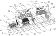
FIG. 1 is a schematic structural view of the present invention;
FIG. 2 is a cross-sectional view of the present invention;
FIG. 3 is a side cross-sectional view of the present invention;
FIG. 4 is an enlarged view of A of FIG. 3 according to the present invention;
FIG. 5 is a cross-sectional view of the mounting box of the present invention;
FIG. 6 is an exploded view of the lift and tilt apparatus of the present invention;
fig. 7 is an exploded view of the blowing device of the present invention.
Reference numbers in the figures: 1. a frame; 2. a heat insulation frame; 3. a protective frame; 4. mounting a box; 5. a controller; 6. a conveying roller; 7. a material placing frame; 8. a first heat insulation plate; 9. rotating the rod; 10. a frame cover; 11. mounting a plate; 12. a second heat insulation plate; 13. a first mounting groove; 14. a fan blade; 15. a support bar; 16. a driven gear; 17. a drive gear; 18. a stepping motor; 19. a connecting rod; 20. heating a tube; 21. a second mounting groove; 22. a sprocket; 23. a chain; 24. a first electric telescopic rod; 25. a receiving groove; 26. a first reduction motor; 27. a second electric telescopic rod; 28. a fixing plate; 29. a second reduction motor; 30. a protective case; 31. a drying zone; 32. a cooling zone.
Detailed Description
The technical solutions in the embodiments of the present invention will be clearly and completely described below with reference to the drawings in the embodiments of the present invention, and it is obvious that the described embodiments are only a part of the embodiments of the present invention, and not all of the embodiments.
Referring to fig. 1-5, a drying device for processing a PCB comprises a frame 1, a heat insulation frame 2 is fixedly installed at the top end of the frame 1, rotating rods 9 with the same structure and linearly distributed are rotated in the frame 1, conveying rollers 6 are fixedly sleeved on the side walls of the rotating rods 9, a material placing frame 7 is placed at the top end of the conveying rollers 6, first heat insulation plates 8 with the same structure are installed at the two ends of the heat insulation frame 2, a drying area 31 and a cooling area 32 are separated from the inside of the heat insulation frame 2 through a second heat insulation plate 12, a lifting device is arranged in the drying area 31, a first installation groove 13 and a second installation groove 21 are symmetrically distributed at the top end of the heat insulation frame 2, a heating pipe 20 is fixedly installed at the bottom end of the second installation groove 21, protective frames 3 are fixedly installed at the top ends of the first installation groove 13 and the second installation groove 21, blowing devices are arranged in the two protective frames 3, and an installation box 4 is fixedly installed at one side of the frame 1, and a controller 5 is fixedly arranged on one side of the mounting box 4, a second speed reducing motor 29 is fixedly arranged on the inner wall of the bottom end of the mounting box 4, a driving device is arranged between the second speed reducing motor 29 and the rotating rod 9, the driving device comprises chain wheels 22 and chains 23, one end of the rotating rod 9 close to the mounting box 4 is rotatably penetrated through the mounting box 4, one end of the rotating rod 9 penetrating through the mounting box 4 is fixedly sleeved with the chain wheels 22, the chains 23 are sleeved between the chain wheels 22, one end of the rotating rod 9 penetrating through the mounting box 4 is fixedly connected with the end part of an output shaft of the second speed reducing motor 29, when the device is used, a worker heats the device by using the heating pipe 20 to achieve the effect of drying the PCB, the PCB is placed in the discharging frame 7 by the worker, the discharging frame 7 is placed on the conveying roller 6 at the same time, one of the rotating rods 9 is driven by the second speed reducing motor 29 to rotate, one of the rotating rods 9 drives the same group of the chain wheels 22 to rotate, sprocket 22 passes through other sprocket 22 rotations of chain 23 drive, and sprocket 22 drive is with organizing dwang 9 to rotate, and dwang 9 drive is with organizing conveying roller 6 to rotate, reaches the effect of conveying blowing frame 7, is convenient for dry, through the setting of drying zone 31 and cooling space 32, makes the device dry and cool off and go on in step, has improved work efficiency and has improved the practicality of device.
Referring to fig. 3-4 and fig. 6, the lifting device comprises a containing groove 25 and first electric telescopic rods 24, the inner walls of both sides of the heat insulation frame 2 are provided with containing grooves 25 with the same structure, the bottom ends of the two containing grooves 25 are fixedly provided with first electric telescopic rods 24, a turning device is arranged between the two first electric telescopic rods 24 and comprises a protective box 30, a second electric telescopic rod 27, a first speed reducing motor 26, a mounting plate 11, a fixing plate 28 and a frame cover 10, the top ends of the two first electric telescopic rods 24 are fixedly provided with protective boxes 30, the opposite sides of the two protective boxes 30 are rotatably provided with second electric telescopic rods 27, one of the protective boxes 30 is fixedly provided with a first speed reducing motor 26, one of the second electric telescopic rods 27 is rotatably penetrated through the protective box 30 near the first speed reducing motor 26, and one of the second electric telescopic rods 27 is fixedly connected with the output shaft end of the first speed reducing motor 26 through one of the protective boxes 30, the equal fixed mounting in framed cover 10 both sides has mounting panel 11, and two mounting panels 11 all are the L type, and two 27 loose axles of second electric telescopic handle all slide and run through the vertical section of homonymy mounting panel 11, and two 27 sliding of second electric telescopic handle run through the equal fixed mounting in mounting panel 11 one end has fixed plate 28, and the equal fixed mounting in the relative one side of two fixed plates 28 has the slipmat.
The program is set by the controller 5, after the PCB is placed, the second speed reducing motor 29 drives the conveying roller 6 to rotate, the feeding frame 7 is conveyed by the conveying roller 6 to enter the drying area 31 through the first heat insulation plate 8, the feeding frame 7 enters the drying area 31, the frame cover 10 is driven to move downwards through the first electric telescopic rod 24, the frame cover 10 is enabled to be attached to the top end of the feeding frame 7, meanwhile, the fixing plates 28 in the same group are driven to move relatively through the second electric telescopic rod 27, the fixing plates 28 are utilized to play a role in fixing the feeding frame 7, anti-slip pads are arranged on the opposite sides of the two fixing plates 28, the sliding of the feeding frame 7 is avoided, the stability of the device is improved, after the fixing of the feeding frame 7 is completed, the feeding frame 7 is driven to ascend through the first electric telescopic rod 24, the device is convenient to rotate, when the feeding frame 7 ascends to a proper position, the second electric telescopic rod 27 on the same side is driven to rotate through the first speed reducing motor 26, the second electric telescopic rod 27 drives the discharging frame 7 and the frame cover 10 to overturn, so that the PCB is overturned, the PCB is made to be evenly dried, and the working efficiency is improved.
Referring to fig. 2-3 and 7, the blowing device includes a stepping motor 18, a support rod 15, fan blades 14, a driving gear 17, a driven gear 16 and a connecting rod 19, the inner walls of the top ends of two protection frames 3 are both fixedly provided with the stepping motor 18, the output shaft of the stepping motor 18 is both fixedly provided with the connecting rod 19, the inner walls of the top ends of the two protection frames 3 are both rotatably provided with the support rod 15, the bottom ends of the same group of support rods 15 and the bottom ends of the connecting rod 19 are both fixedly provided with the fan blades 14 which have the same structure and are distributed in an annular array, the side walls of the connecting rod 19 are both fixedly sleeved with the driving gear 17, the side walls of the support rods 15 are both fixedly sleeved with the driven gear 16, the driving gear 17 is both meshed with the same group of driven gear 16, the bottom ends of the first insulation board 8 and the second insulation board 12 are both in a comb shape, the bottom ends of the first installation groove 13 and the second installation groove 21 are both in a filter mesh shape, the model of the controller 5 is SC200, and the second reducing motor 29 is electrically connected with the controller 5, when the device is operated, the heating pipe 20 provides heat for the drying area 31, two stepping motors 18 are simultaneously started, the stepping motors 18 drive the connecting rods 19 at the same side to rotate, the connecting rods 19 drive the driving gears 17 to rotate, the driving gears 17 drive the driven gears 16 in the same group to rotate, the driven gears 16 drive the supporting rods 15 in the same group to rotate, the connecting rods 19 and the supporting rods 15 drive the fan blades 14 in the same group to rotate, the blowing device of the drying area 31 plays a role in accelerating the circulation of hot air, the drying efficiency is improved, and the PCB can be uniformly dried by matching with a turnover device, the working efficiency is improved, when one group of PCB is dried, the discharging frame 7 is transported into the cooling area 32 through the driving device, the blowing device arranged in the cooling area 32 achieves the effect of heat dissipation and cooling, and is convenient for workers to discharge, avoid the staff to scald because of high temperature, improved the security of device, and improved staff's life health, the device has stoving and refrigerated function, has improved the practicality of device.
The above description is only for the preferred embodiment of the present invention, but the scope of the present invention is not limited thereto, and any person skilled in the art should be considered to be within the technical scope of the present invention, and equivalent alternatives or modifications according to the technical solution of the present invention and the inventive concept thereof should be covered by the scope of the present invention.
Claims (6)
1. A drying device for processing a PCB (printed Circuit Board) comprises a frame (1) and is characterized in that a heat insulation frame (2) is fixedly installed at the top end of the frame (1), rotating rods (9) which are identical in structure and distributed linearly are rotated in the frame (1), conveying rollers (6) are fixedly sleeved on the side walls of the rotating rods (9), a material placing frame (7) is placed at the top end of the conveying rollers (6), first heat insulation plates (8) which are identical in structure are installed at the two ends of the heat insulation frame (2), a drying area (31) and a cooling area (32) are separated from the inside of the heat insulation frame (2) through second heat insulation plates (12), a lifting device is arranged in the drying area (31), first mounting grooves (13) and second mounting grooves (21) which are symmetrically distributed are formed in the top end of the heat insulation frame (2), and a heating pipe (20) is fixedly installed on the inner wall of the bottom end of the second mounting groove (21), just first mounting groove (13) and the equal fixed mounting in second mounting groove (21) top have protective frame (3), two all be equipped with blast apparatus in protective frame (3), just frame (1) one side fixed mounting has mounting box (4), just mounting box (4) one side fixed mounting has controller (5), mounting box (4) bottom inner wall fixed mounting has second gear motor (29), just be equipped with drive arrangement between second gear motor (29) and dwang (9).
2. The drying device for processing the PCB as claimed in claim 1, wherein the lifting device comprises a storage groove (25) and a first electric telescopic rod (24), the storage grooves (25) with the same structure are formed in the inner walls of the two sides of the heat insulation frame (2), the bottom ends of the two storage grooves (25) are fixedly provided with the first electric telescopic rod (24), and a turnover device is arranged between the two first electric telescopic rods (24).
3. The drying device for processing the PCB as claimed in claim 2, wherein the turnover device comprises a protective box (30), second electric telescopic rods (27), first speed reducing motors (26), a mounting plate (11), a fixing plate (28) and a frame cover (10), the protective box (30) is fixedly mounted at the top end of each of the two first electric telescopic rods (24), the second electric telescopic rods (27) are rotatably mounted at the opposite side of each of the two protective boxes (30), the first speed reducing motor (26) is fixedly mounted in one of the protective boxes (30), one of the second electric telescopic rods (27) is rotatably penetrated through the protective box (30) near the end of the first speed reducing motor (26), and one end of one of the second electric telescopic rods (27) penetrating through the protective box (30) is fixedly connected with the end of the output shaft of the first speed reducing motor (26), the equal fixed mounting in framed cover (10) both sides has mounting panel (11), and two mounting panel (11) all are the L type, two second electric telescopic handle (27) loose axle all slides and runs through the homonymy the vertical section of mounting panel (11), and two second electric telescopic handle (27) slide and run through the equal fixed mounting in mounting panel (11) one end and have fixed plate (28), two the equal fixed mounting in one side relatively of fixed plate (28) has the slipmat.
4. The drying device for processing the PCB as recited in claim 1, wherein the blowing device comprises a stepping motor (18), a support rod (15), fan blades (14), a driving gear (17), a driven gear (16) and a connecting rod (19), the stepping motor (18) is fixedly mounted on the inner wall of the top end of each of the two protection frames (3), the connecting rod (19) is fixedly mounted on the output shaft of each of the stepping motors (18), the support rod (15) is rotatably mounted on the inner wall of the top end of each of the two protection frames (3), the fan blades (14) which have the same structure and are distributed in an annular array are fixedly mounted at the bottom ends of the support rod (15) and the connecting rod (19) in the same group, the driving gear (17) is fixedly sleeved on the side wall of each of the connecting rod (19), and the driven gear (16) is fixedly sleeved on the side wall of each of the support rod (15), the driving gears (17) are all meshed with the driven gears (16) of the same group.
5. The drying device for processing the PCB circuit board according to claim 1, wherein the driving device comprises a chain wheel (22) and a chain (23), the rotating rod (9) is close to one end of the mounting box (4) and is rotated to penetrate through the mounting box (4), the rotating rod (9) penetrates through one end of the mounting box (4) and is fixedly sleeved with the chain wheel (22), the chain (23) is sleeved between the chain wheels (22), and one of the chain wheel (9) penetrates through one end of the mounting box (4) and is fixedly connected with the end part of the output shaft of the second speed reduction motor (29).
6. The drying device for processing the PCB as recited in claim 1, wherein the bottom ends of the first and second heat insulation boards (8, 12) are both in a comb shape, the bottom ends of the first and second installation grooves (13, 21) are both in a filter net shape, the controller (5) is SC200, and the second speed reduction motor (29) is electrically connected with the controller (5).
Priority Applications (1)
| Application Number | Priority Date | Filing Date | Title |
|---|---|---|---|
| CN202122195428.4U CN216048954U (en) | 2021-09-11 | 2021-09-11 | Drying device is used in processing of PCB circuit board |
Applications Claiming Priority (1)
| Application Number | Priority Date | Filing Date | Title |
|---|---|---|---|
| CN202122195428.4U CN216048954U (en) | 2021-09-11 | 2021-09-11 | Drying device is used in processing of PCB circuit board |
Publications (1)
| Publication Number | Publication Date |
|---|---|
| CN216048954U true CN216048954U (en) | 2022-03-15 |
Family
ID=80598198
Family Applications (1)
| Application Number | Title | Priority Date | Filing Date |
|---|---|---|---|
| CN202122195428.4U Active CN216048954U (en) | 2021-09-11 | 2021-09-11 | Drying device is used in processing of PCB circuit board |
Country Status (1)
| Country | Link |
|---|---|
| CN (1) | CN216048954U (en) |
-
2021
- 2021-09-11 CN CN202122195428.4U patent/CN216048954U/en active Active
Similar Documents
| Publication | Publication Date | Title |
|---|---|---|
| CN210586142U (en) | Boiling assembly line operation device | |
| CN216048954U (en) | Drying device is used in processing of PCB circuit board | |
| CN219112102U (en) | Roller type tunnel heating device | |
| CN212747241U (en) | A drying equipment for PCB board processing | |
| CN210922077U (en) | Drying and cooling device suitable for 5G substrate | |
| CN213300734U (en) | Efficient electric heat blast air drying cabinet | |
| CN211152576U (en) | Network security rack heat abstractor | |
| CN211915759U (en) | Novel reflow soldering equipment | |
| CN212778516U (en) | Seed processing and grading drying equipment | |
| CN210969539U (en) | Injection molding raw materials dries by fire material mechanism | |
| CN113414078A (en) | Heating device and inflation valve baking equipment | |
| CN111848218A (en) | Semiconductor ceramic assembling and packaging device and using method thereof | |
| CN218410614U (en) | Circuit board drying cabinet | |
| CN215261020U (en) | Drying equipment for automobile filter element | |
| CN114877632B (en) | Wood drying device for woodwork processing | |
| CN220472086U (en) | Multidirectional uniform drying equipment | |
| CN218830800U (en) | Cooling frame of integrated circuit jig | |
| CN219178165U (en) | Efficient tealeaves drying device | |
| CN214529134U (en) | Heat treatment device for disc brake calipers | |
| CN220707959U (en) | Sectional heating oven for insulating fiber tube production | |
| CN220781081U (en) | Wood toy paint surface drying device | |
| CN218550287U (en) | Drying device is used in processing of PCB circuit board | |
| CN218936840U (en) | Industrial belt production is with high-efficient drying device | |
| CN214709950U (en) | Chain oven | |
| CN216752261U (en) | High-efficient PCB board toasts line |
Legal Events
| Date | Code | Title | Description |
|---|---|---|---|
| GR01 | Patent grant | ||
| GR01 | Patent grant |