CN216004008U - Auxiliary conveying mechanism of environment-friendly paperboard stacking equipment - Google Patents
Auxiliary conveying mechanism of environment-friendly paperboard stacking equipment Download PDFInfo
- Publication number
- CN216004008U CN216004008U CN202121381650.7U CN202121381650U CN216004008U CN 216004008 U CN216004008 U CN 216004008U CN 202121381650 U CN202121381650 U CN 202121381650U CN 216004008 U CN216004008 U CN 216004008U
- Authority
- CN
- China
- Prior art keywords
- fixed
- gangbar
- environment
- conveying mechanism
- driving motor
- Prior art date
- Legal status (The legal status is an assumption and is not a legal conclusion. Google has not performed a legal analysis and makes no representation as to the accuracy of the status listed.)
- Expired - Fee Related
Links
Images


Abstract
The utility model discloses an auxiliary conveying mechanism of environment-friendly paperboard stacking equipment, and relates to the field of environment-friendly paperboard stacking. Including fixed baseplate and pushing equipment, fixed baseplate's top fixed mounting has the guide frame, the discharge gate has been seted up to one side of fixed baseplate, pushing equipment includes driving motor, the carousel, the gangbar, the fixed block, the gangbar, driven lever and ejector pin, driving motor fixed mounting is in fixed baseplate's front, carousel and driving motor's output fixed connection, the gangbar sets up in the front of carousel, the inside of gangbar is located to the fixed block cover, the top of gangbar is located to the driven lever cover, the one end fixed connection of ejector pin and driven lever, the utility model discloses an utilize pushing equipment's design, pushing equipment can release the inside environmental protection cardboard raw materials intermittent type nature of guide frame from the discharge gate, then the environmental protection cardboard just can fall to carry on the transmission shaft, intermittent type nature pushes away the material and can not pile up the environmental protection cardboard on making the transmission shaft.
Description
Technical Field
The utility model relates to the technical field of environment-friendly paperboard stacking, in particular to an auxiliary conveying mechanism of environment-friendly paperboard stacking equipment.
Background
Along with the continuous reinforcing of people's environmental protection consciousness, people are also expanding gradually to the use of environmental protection material, and the market demand is also increasing as the packaging material who uses commonly, and environmental protection cardboard often needs pile up neatly equipment to put things in good order in production transportation, just need transport the environmental protection cardboard in advance on the pile up neatly equipment.
The existing stacking equipment is used for stacking the environment-friendly paper boards, the mechanical arms are adopted for transferring and stacking the environment-friendly paper boards, a certain period is needed for mechanical taking and placing of the environment-friendly paper boards, but the existing conveying mechanism does not have the intermittent feeding function, and therefore a large amount of stacked environment-friendly paper boards to be stacked can be accumulated on the conveying mechanism.
SUMMERY OF THE UTILITY MODEL
Technical problem to be solved
Aiming at the defects of the prior art, the utility model discloses an auxiliary conveying mechanism of environment-friendly paperboard stacking equipment, which aims to solve the problems in the background art.
(II) technical scheme
In order to achieve the purpose, the utility model is realized by the following technical scheme: an auxiliary conveying mechanism of environment-friendly paperboard stacking equipment comprises:
the guide frame is fixedly mounted at the top end of the fixed base, a discharge hole is formed in one side of the fixed base, the bottom of the fixed base is fixedly connected with a bearing table, and a plurality of transmission shafts are sleeved at the top end of the bearing table;
pushing equipment, pushing equipment includes driving motor, carousel, gangbar, fixed block, gangbar, driven lever and ejector beam, driving motor fixed mounting is in fixed baseplate's front, carousel and driving motor's output fixed connection, the gangbar sets up in the front of carousel, the inside of gangbar is located to the fixed block cover, just fixed block and carousel fixed connection, the top of gangbar is located to the driven lever cover, the one end fixed connection of ejector beam and driven lever, just the ejector beam runs through fixed baseplate's top.
Preferably, the front surface of the fixed base is fixedly provided with a fixed plate, the fixed plate is sleeved on the outer side of the output end of the driving motor, and the fixed plate is arranged on the back surface of the turntable.
Preferably, the bottom of the linkage rod is sleeved with a fixed pin shaft, and one end of the fixed pin shaft is fixedly connected with one side of the fixed plate.
Preferably, the bottom of the linkage rod is provided with an elliptical groove, the elliptical groove is sleeved outside the fixed block, the top of the linkage rod is provided with a U-shaped groove, and the U-shaped groove is sleeved outside the driven rod.
Preferably, the top of the fixed base is provided with a through groove, and the through groove is sleeved on the outer side of the material pushing rod.
Preferably, the both sides that lead to the groove inner wall have all been seted up the spout, two the inside of spout all is equipped with the slider, two the one end that the slider is relative and the both sides fixed connection of ejector pad pole.
The utility model discloses an auxiliary conveying mechanism of environment-friendly paperboard stacking equipment, which has the following beneficial effects:
1. the utility model discloses an utilize pushing equipment's design, pushing equipment can release the inside environmental protection cardboard raw materials intermittent type nature of guide frame from the discharge gate, then the environmental protection cardboard just can fall into to transport on the transmission shaft, and the accumulational phenomenon of environmental protection cardboard can not appear on the material returned messenger transmission shaft of intermittent type nature to this indirect assurance is put things in good order equipment and can be gone on with disorder.
2. The utility model discloses an utilize the design of ejector pad pole, the ejector pad pole can also hinder the inside environmental protection cardboard of guide frame can not fall into fixed baseplate's inside pushing away the material in-process, treats that the ejector pad pole can break away from the lower port of guide frame after removing half cycle, treats that the ejector pad pole can continue again to release the environmental protection cardboard after the environmental protection cardboard falls down to this alright purpose that realizes intermittent type nature pay-off.
Drawings
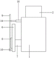
FIG. 1 is a schematic view of the overall structure of the present invention;
FIG. 2 is a schematic overall side view of the present invention;
FIG. 3 is an enlarged view of the structure at A in FIG. 1 according to the present invention.
In the figure: 1. a fixed base; 2. a material guiding frame; 3. a discharge port; 4. a bearing table; 5. a drive shaft; 6. a fixing plate; 7. a drive motor; 8. a turntable; 9. a linkage rod; 10. fixing a pin shaft; 11. a fixed block; 12. an elliptical trough; 13. a U-shaped groove; 14. a driven lever; 15. a through groove; 16. a material pushing rod; 17. a chute; 18. a slide block.
Detailed Description
The embodiment of the utility model discloses an auxiliary conveying mechanism of environment-friendly paperboard stacking equipment, which comprises a fixed base 1, wherein a material guide frame 2 is fixedly arranged at the top end of the fixed base 1, the material guide frame 2 is used for storing environment-friendly paperboards, a material outlet 3 is formed in one side of the fixed base 1, the width of the environment-friendly paperboards at the width of the material outlet 3 is consistent, so that the condition that the material guide frame 2 can only fall down one environment-friendly paperboard to enter the inside of the fixed base 1 at one time is ensured, a bearing table 4 is fixedly connected to the bottom of the fixed base 1, a plurality of transmission shafts 5 are sleeved at the top end of the bearing table 4, and the transmission shafts 5 are used for transmitting the environment-friendly paperboards;
referring to the attached drawings 1 and 2, the material pushing mechanism comprises a driving motor 7, a rotary table 8, a linkage rod 9, a fixed block 11, a linkage rod 9, a driven rod 14 and a material pushing rod 16, wherein the driving motor 7 is fixedly arranged on the front surface of a fixed base 1, the driving motor 7 is electrically connected with an external power supply through an external switch, the rotary table 8 is fixedly connected with the output end of the driving motor 7, the linkage rod 9 is arranged on the front surface of the rotary table 8, a fixed pin shaft 10 is sleeved at the bottom of the linkage rod 9, one end of the fixed pin shaft 10 is fixedly connected with one side of a fixed plate 6, the fixed pin shaft 10 is T-shaped, the linkage rod 9 cannot change position when swinging along the outside of the fixed pin shaft 10, the fixed block 11 is sleeved inside the linkage rod 9, the fixed block 11 is cylindrical, an elliptical groove 12 is formed in the bottom of the linkage rod 9, the inner wall of the elliptical groove 12 is attached to the outer wall of the fixed block 11, the oval groove 12 is sleeved outside the fixed block 11, the linkage rod 9 can be reversely pushed once when the fixed block 11 rotates by one hundred eighty degrees, so that the reciprocating swing of the linkage rod 9 is realized, the fixed block 11 is fixedly connected with the rotary table 8, the driven rod 14 is sleeved at the top of the linkage rod 9, the top of the linkage rod 9 is provided with a U-shaped groove 13, the U-shaped groove 13 is sleeved outside the driven rod 14, the inner wall of the U-shaped groove 13 is attached to the outer wall of the driven rod 14, so that the synchronization of the movement of the linkage rod 9 and the driven rod 14 is ensured, the pushing rod 16 is fixedly connected with one end of the driven rod 14, the pushing rod 16 penetrates through the top of the fixed base 1, the pushing rod 16 can reciprocate in the fixed base 1 under the action of the driven rod 14, so that the environment-friendly paper board falling from the guide frame 2 can be intermittently pushed out from the discharge port 3, and the pushing rod 16 can block the environment-friendly paper board in the guide frame 2 from falling in the pushing process, and the material pushing rod 16 can push only one environment-friendly paperboard each time.
Through groove 15 has been seted up at fixed baseplate 1's top, leads to groove 15 and cup joints in the outside of ejector pad pole 16, leads to the both sides of groove 15 inner wall and has all seted up spout 17, and the inside of two spout 17 all is overlapped and is equipped with slider 18, and the both sides fixed connection of two 18 relative one ends of slider and ejector pad pole 16, slider 18 can restrict ejector pad pole 16 and only can lead to the inside translation of groove 15.
The fixed plate 6 is fixedly arranged on the front face of the fixed base 1, the fixed plate 6 is sleeved on the outer side of the output end of the driving motor 7, the fixed plate 6 is arranged on the back face of the rotary table 8, the fixed plate 6 serves as a support for the pushing mechanism, and the upper end of the fixed plate 6 is flush with the port of the through groove 15.
The working principle is as follows: when the environment-friendly paper board is used, an operator firstly places the environment-friendly paper board in the guide frame 2, then the driving motor 7 is operated, the output end of the driving motor 7 drives the rotary disc 8 to rotate, the rotary disc 8 drives the fixed block 11 to synchronously rotate, the fixed block 11 extrudes the linkage rod 9 and moves in the elliptical groove 12, and after the fixed block 11 rotates one hundred eighty degrees, the fixed block 11 reversely extrudes the linkage rod 9, so that the linkage rod 9 can swing in a reciprocating mode.
Gangbar 9 rotates along the outer wall of fixed pin axle 10, gangbar 9 extrudes driven lever 14 simultaneously, driven lever 14 drives ejector beam 16 and removes in the inside that leads to groove 15, and then ejector beam 16 drives slider 18 and removes along the inside of spout 17, treat that ejector beam 16 is after the lower port roll-off of guide frame 2, the environmental protection cardboard will fall into the inside of unable adjustment base 1, when taking ejector beam 16 reverse movement, the environmental protection cardboard atress removes to the outside of discharge gate 3, the top that transmission shaft 5 will fall into to last environmental protection cardboard, with this defeated material of supplementary environmental protection cardboard intermittent type nature.
The foregoing shows and describes the general principles and broad features of the present invention and advantages thereof. It will be understood by those skilled in the art that the present invention is not limited to the embodiments described above, which are described in the specification and illustrated only to illustrate the principle of the present invention, but that various changes and modifications may be made therein without departing from the spirit and scope of the present invention, which fall within the scope of the utility model as claimed. The scope of the utility model is defined by the appended claims and equivalents thereof.
Claims (6)
1. The utility model provides an environmental protection cardboard pile up neatly equipment's supplementary conveying mechanism which characterized in that: the method comprises the following steps:
the device comprises a fixed base (1), wherein a material guide frame (2) is fixedly mounted at the top end of the fixed base (1), a discharge hole (3) is formed in one side of the fixed base (1), a bearing table (4) is fixedly connected to the bottom of the fixed base (1), and a plurality of transmission shafts (5) are sleeved at the top end of the bearing table (4);
pushing equipment, pushing equipment includes driving motor (7), carousel (8), gangbar (9), fixed block (11), gangbar (9), driven lever (14) and ejector tie rod (16), driving motor (7) fixed mounting is in the front of unable adjustment base (1), the output fixed connection of carousel (8) and driving motor (7), gangbar (9) set up in the front of carousel (8), the inside of gangbar (9) is located to fixed block (11) cover, just fixed block (11) and carousel (8) fixed connection, the top of gangbar (9) is located to driven lever (14) cover, the one end fixed connection of ejector tie rod (16) and driven lever (14), just ejector tie rod (16) run through the top of unable adjustment base (1).
2. The auxiliary conveying mechanism of the environment-friendly paperboard stacking equipment as claimed in claim 1, wherein: the front side of the fixed base (1) is fixedly provided with a fixed plate (6), the fixed plate (6) is sleeved on the outer side of the output end of the driving motor (7), and the fixed plate (6) is arranged on the back side of the turntable (8).
3. The auxiliary conveying mechanism of the environment-friendly paperboard stacking equipment as claimed in claim 1, wherein: the bottom cover of gangbar (9) is equipped with fixed pin axle (10), the one end of fixed pin axle (10) and one side fixed connection of fixed plate (6).
4. The auxiliary conveying mechanism of the environment-friendly paperboard stacking equipment as claimed in claim 1, wherein: an elliptical groove (12) is formed in the bottom of the linkage rod (9), the elliptical groove (12) is sleeved outside the fixed block (11), a U-shaped groove (13) is formed in the top of the linkage rod (9), and the U-shaped groove (13) is sleeved on the outer side of the driven rod (14).
5. The auxiliary conveying mechanism of the environment-friendly paperboard stacking equipment as claimed in claim 1, wherein: a through groove (15) is formed in the top of the fixed base (1), and the through groove (15) is sleeved on the outer side of the material pushing rod (16).
6. The auxiliary conveying mechanism of the environment-friendly paperboard stacking equipment as claimed in claim 5, wherein: both sides of the inner wall of the through groove (15) are provided with sliding grooves (17), two sliding blocks (18) are sleeved inside the sliding grooves (17), and two ends, opposite to the sliding blocks (18), of the sliding blocks are fixedly connected with both sides of the pushing rod (16).
Priority Applications (1)
| Application Number | Priority Date | Filing Date | Title |
|---|---|---|---|
| CN202121381650.7U CN216004008U (en) | 2021-06-22 | 2021-06-22 | Auxiliary conveying mechanism of environment-friendly paperboard stacking equipment |
Applications Claiming Priority (1)
| Application Number | Priority Date | Filing Date | Title |
|---|---|---|---|
| CN202121381650.7U CN216004008U (en) | 2021-06-22 | 2021-06-22 | Auxiliary conveying mechanism of environment-friendly paperboard stacking equipment |
Publications (1)
| Publication Number | Publication Date |
|---|---|
| CN216004008U true CN216004008U (en) | 2022-03-11 |
Family
ID=80585629
Family Applications (1)
| Application Number | Title | Priority Date | Filing Date |
|---|---|---|---|
| CN202121381650.7U Expired - Fee Related CN216004008U (en) | 2021-06-22 | 2021-06-22 | Auxiliary conveying mechanism of environment-friendly paperboard stacking equipment |
Country Status (1)
| Country | Link |
|---|---|
| CN (1) | CN216004008U (en) |
Cited By (1)
| Publication number | Priority date | Publication date | Assignee | Title |
|---|---|---|---|---|
| CN115394685A (en) * | 2022-08-20 | 2022-11-25 | 江西瑞晟光电科技有限公司 | COB multi-chip integrated packaging device and packaging method |
-
2021
- 2021-06-22 CN CN202121381650.7U patent/CN216004008U/en not_active Expired - Fee Related
Cited By (2)
| Publication number | Priority date | Publication date | Assignee | Title |
|---|---|---|---|---|
| CN115394685A (en) * | 2022-08-20 | 2022-11-25 | 江西瑞晟光电科技有限公司 | COB multi-chip integrated packaging device and packaging method |
| CN115394685B (en) * | 2022-08-20 | 2024-01-12 | 江西瑞晟光电科技有限公司 | COB multi-chip integrated packaging device and packaging method |
Similar Documents
| Publication | Publication Date | Title |
|---|---|---|
| CN108016865A (en) | A kind of feed device of conveying sheet belt | |
| CN208470289U (en) | A kind of carton unpacking machine suitable for different sizes | |
| CN216004008U (en) | Auxiliary conveying mechanism of environment-friendly paperboard stacking equipment | |
| CN209410961U (en) | A kind of AI plug-in machine with automatic plate feeding device | |
| CN204035296U (en) | Automatically packaging facilities is cut | |
| CN208197096U (en) | Automatic brick-equipment | |
| CN207154849U (en) | A kind of steel plate is continuously cut and blanking device | |
| CN108942248A (en) | A kind of battery nickel band is cut automatically puts spot welding device | |
| CN203174432U (en) | Front edge paper conveying device of servo system | |
| CN215047214U (en) | Corrugated board turning plate device | |
| CN203283470U (en) | Automatic straw feeding mechanism | |
| CN206551541U (en) | A kind of self-feeding platform mechanism | |
| CN216424954U (en) | Glove packaging machine | |
| CN214027418U (en) | Carton cuts uses suppression device | |
| CN108099370A (en) | Full-automatic video contraposition moving type precision screen-printing machine | |
| CN210062231U (en) | Adjustable indentator is used in corrugated paper production | |
| CN210480258U (en) | Rotary boring feeding structure of automatic pipe feeding machine | |
| CN210998891U (en) | Speed-adjustable corrugated board transverse cutting device | |
| CN207748078U (en) | A kind of rectangular paper extraction sack filling machine | |
| CN210363034U (en) | Automatic stamping machine | |
| CN207258705U (en) | A kind of double ridge positioning cylinder cam-type driven member heavy duty backswing devices | |
| CN202121010U (en) | Automatic pole piece wrapping machine for storage battery | |
| CN218707528U (en) | Paperboard feeding mechanism | |
| CN218706782U (en) | Multi-station plate collecting machine | |
| CN214447264U (en) | A cloth system for leaking dropping board |
Legal Events
| Date | Code | Title | Description |
|---|---|---|---|
| GR01 | Patent grant | ||
| GR01 | Patent grant | ||
| CF01 | Termination of patent right due to non-payment of annual fee |
Granted publication date: 20220311 |
|
| CF01 | Termination of patent right due to non-payment of annual fee |