CN215968058U - Alignment rolling and alignment device for grinding machine machining - Google Patents
Alignment rolling and alignment device for grinding machine machining Download PDFInfo
- Publication number
- CN215968058U CN215968058U CN202121889736.0U CN202121889736U CN215968058U CN 215968058 U CN215968058 U CN 215968058U CN 202121889736 U CN202121889736 U CN 202121889736U CN 215968058 U CN215968058 U CN 215968058U
- Authority
- CN
- China
- Prior art keywords
- gear
- bottom plate
- grinding machine
- rolling
- movable rod
- Prior art date
- Legal status (The legal status is an assumption and is not a legal conclusion. Google has not performed a legal analysis and makes no representation as to the accuracy of the status listed.)
- Active
Links
- 238000005096 rolling process Methods 0.000 title claims abstract description 13
- 238000003754 machining Methods 0.000 title claims description 11
- 238000003466 welding Methods 0.000 claims description 3
- 238000001125 extrusion Methods 0.000 claims 1
- 230000005540 biological transmission Effects 0.000 abstract description 2
- 238000000034 method Methods 0.000 description 6
- 238000012423 maintenance Methods 0.000 description 2
- 239000000463 material Substances 0.000 description 2
- 230000004048 modification Effects 0.000 description 2
- 238000012986 modification Methods 0.000 description 2
- 238000005498 polishing Methods 0.000 description 2
- 229910000760 Hardened steel Inorganic materials 0.000 description 1
- 239000003082 abrasive agent Substances 0.000 description 1
- 229910045601 alloy Inorganic materials 0.000 description 1
- 239000000956 alloy Substances 0.000 description 1
- 230000009286 beneficial effect Effects 0.000 description 1
- 238000005516 engineering process Methods 0.000 description 1
- 239000011521 glass Substances 0.000 description 1
- 239000010438 granite Substances 0.000 description 1
- 238000009958 sewing Methods 0.000 description 1
- 230000003746 surface roughness Effects 0.000 description 1
Images


Abstract
The utility model is suitable for the technical field of grinding machines, and provides a straightening, rolling and aligning device for grinding machine processing, which comprises a bottom plate, wherein one side of the top of the bottom plate is fixedly connected with a control console, a motor accommodating tank is arranged inside the control console, a motor is arranged inside the motor accommodating tank, a rotating shaft is arranged on the outer surface of one side of the motor, one end of the rotating shaft penetrates outside the control console in a sliding manner, a first gear is fixedly sleeved at one end of the rotating shaft, two fixed seats are welded at the top of the bottom plate close to the center, the transmission capability of the device is greatly improved through the arrangement of the rotating shaft and the first gear, a rotating rod can be more stable in work through the arrangement of the fixed seats, the overall practicability of the device is greatly improved through the arrangement of roller groups, and the working efficiency of the device is improved, through the arrangement of the nut, the replacement and the disassembly of the roller group become more convenient and faster.
Description
Technical Field
The utility model belongs to the technical field of grinding machines, and particularly relates to a straightening, rolling and aligning device for machining of a grinding machine.
Background
Grinding machines are machine tools for grinding the surface of a workpiece by using a grinding tool, and in the eighteenth century, in order to adapt to the hardened machining of parts such as clocks, bicycles, sewing machines and firearms, grinding machines using a natural abrasive grinding wheel were developed in the uk, germany and the usa respectively. Most grinding machines perform grinding using a grinding wheel rotating at a high speed, and a few grinding machines perform grinding using oilstones, sanding belts and other grinders and free abrasives, such as honing machines, superfinishing machines, sanding belt grinders, grinding machines, polishing machines, and the like. The grinder can process materials with higher hardness, such as hardened steel, hard alloy and the like, and can also process brittle materials, such as glass and granite. The grinding machine can grind with high precision and small surface roughness, and can grind with high efficiency, such as strong grinding.
The existing traditional technology is that the parts are processed after the parts are fixed through the fixing seat, only the parts are simply fixed, when the grinding machine device works, the parts cannot be straightened and rolled fixedly through the device, the grinding machine cannot accurately process the parts, and the working efficiency of the whole grinding machine device is greatly reduced.
SUMMERY OF THE UTILITY MODEL
The utility model provides a straightening, rolling and aligning device for machining of a grinding machine, and aims to solve the problems that when the grinding machine works, parts cannot be straightened, rolled and fixed through the device, the parts cannot be accurately machined through the grinding machine, and the working efficiency of the whole grinding machine device is greatly reduced.
The utility model is realized in such a way, the straightening, rolling and aligning device for grinding machine processing comprises a bottom plate, wherein one side of the top of the bottom plate is fixedly connected with a control console, a motor accommodating groove is formed in the control console, a motor is installed in the motor accommodating groove, a rotating shaft is arranged on the outer surface of one side of the motor, one end of the rotating shaft penetrates through the control console in a sliding manner, a first gear is fixedly sleeved at one end of the rotating shaft, two fixing seats are welded at the position, close to the center, of the top of the bottom plate, rotating rods penetrate between the insides of the two fixing seats in a sliding manner, the two ends of each rotating rod extend to the outsides of the two fixing seats, a second gear and a third gear are fixedly sleeved at one end of each rotating rod respectively, the second gear and the third gear are meshed with the first gear and connected with each other, and roller groups are sleeved at the outer surfaces of the two rotating rods, close to the edges of the other ends, and two nuts are sleeved on the other ends of the rotating rods in a threaded manner.
Preferably, the outer surface of one side of control cabinet is provided with the hollow shaft, the inside sliding connection of hollow shaft has the movable rod, the outer surface sliding sleeve of movable rod is equipped with first fixed block, and the bottom fixed connection of first fixed block is at the top of bottom plate.
Preferably, the top welding of bottom plate has the mount, the inside top surface center fixedly connected with second fixed block of mount, the surface of movable rod and the center department of second fixed block slide and run through, and the one end of movable rod extends to the outside of second fixed block.
Preferably, one end of the movable rod is fixedly connected with a magnetic pushing block.
Preferably, a control panel is arranged on the outer surface of the other side of the control console.
Preferably, the base is welded at four corners of the bottom plate.
Compared with the prior art, the utility model has the beneficial effects that: the utility model relates to a straightening, rolling and aligning device for grinding machine processing, which is characterized in that after a device is started by a control panel, a part to be processed and polished is placed between two roller groups, a rotating shaft on a control console drives a first gear to work, the first gear drives a second gear and a third gear to drive two rotating rods to rotate, fixed seats are sleeved on the two rotating rods to enable the rotating rods to be more stable in work, the two roller groups are driven by the two rotating rods to roll, so that the part can be more stable in the processing process, the arrangement of a hollow shaft drives a movable rod to stretch and align, the first fixed block and the second fixed block enable the movable rod to work more stably, a magnetic pushing block is driven to push the part to perform aligning processing work, the work efficiency of the whole device is effectively improved, and after the work is stopped, the roller set can be taken down by twisting the nut, so that the maintenance and the replacement of the roller set are more convenient.
Drawings
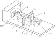
FIG. 1 is a schematic front view of the present invention;
FIG. 2 is a side view of the present invention;
FIG. 3 is an enlarged view of the structure at A in FIG. 2 according to the present invention;
in the figure: 1. a base plate; 2. a console; 3. a control panel; 4. a motor accommodating groove; 5. a fixed mount; 6. a rotating shaft; 7. a hollow shaft; 8. a motor; 9. a movable rod; 10. a first gear; 11. a second gear; 12. a third gear; 13. a first fixed block; 14. rotating the rod; 15. a fixed seat; 16. a magnetic pushing block; 17. a roller set; 18. a nut; 19. a second fixed block; 20. a base.
Detailed Description
In order that the above objects, features and advantages of the present invention can be more clearly understood, the present invention will be further described with reference to the accompanying drawings and examples. It should be noted that the embodiments and features of the embodiments of the present application may be combined with each other without conflict.
In the following description, numerous specific details are set forth in order to provide a thorough understanding of the present invention, however, the present invention may be practiced in other ways than those specifically described herein, and thus the present invention is not limited to the specific embodiments of the present disclosure.
Referring to fig. 1-3, the present invention provides a technical solution of a straightening, rolling and aligning device for grinding machine processing: comprises a bottom plate 1, a control console 2 is fixedly connected with one side of the top of the bottom plate 1, a motor accommodating groove 4 is arranged in the control console 2, a motor 8 is arranged in the motor accommodating groove 4, a rotating shaft 6 is arranged on the outer surface of one side of the motor 8, one end of the rotating shaft 6 penetrates to the outside of the control console 2 in a sliding manner, one end of the rotating shaft 6 is fixedly sleeved with a first gear 10, two fixed seats 15 are welded at the top part of the bottom plate 1 close to the center, rotating rods 14 penetrate between the two fixed seats 15 in a sliding manner, and both ends of the rotating rod 14 extend to the outside of the two fixed seats 15, one end of each of the two rotating rods 14 is fixedly sleeved with the second gear 11 and the third gear 12 respectively, and the second gear 11 and the third gear 12 are engaged with the first gear 10, the outer surfaces of the two rotating rods 14 are all sleeved with roller groups 17 near the edges of the other ends, and the other ends of the two rotating rods 14 are all sleeved with nuts 18 through threads.
In this embodiment, through the setting of pivot 6 and first gear 10 for the transmission capacity of device has obtained very big promotion, through the setting of fixing base 15, makes dwang 14 can be more steady in service, through the setting of wheel train 17, makes the whole practicality of device obtain very big promotion, thereby has improved the work efficiency of device, through the setting of nut 18, makes the change dismantlement of wheel train 17 become more convenient and fast.
Further, a hollow shaft 7 is arranged on the outer surface of one side of the control console 2, a movable rod 9 is connected to the inside of the hollow shaft 7 in a sliding mode, a first fixing block 13 is sleeved on the outer surface of the movable rod 9 in a sliding mode, and the bottom end of the first fixing block 13 is fixedly connected to the top of the bottom plate 1.
In this embodiment, through the setting of hollow shaft 7 and first fixed block 13 for the stability of movable rod 9 has obtained very big promotion, and after the device was worked, the basis of calibrating and polishing was provided.
Further, the top welding of bottom plate 1 has mount 5, and the inside top surface center department fixedly connected with second fixed block 19 of mount 5, and the surface of movable rod 9 and the center department of second fixed block 19 slide and run through, and the one end of movable rod 9 extends to the outside of second fixed block 19.
In the embodiment, the fixed frame 5 and the second fixed block 19 are arranged, so that the stability of the movable rod 9 is further improved when the movable rod works.
Further, one end of the movable rod 9 is fixedly connected with a magnetic pushing block 16.
In this embodiment, the arrangement of the magnetic pushing block 16 greatly improves the stability of the device, and is more convenient to align, so that the working efficiency is greatly improved.
Further, the other side outer surface of the console 2 is provided with a control panel 3.
In the present embodiment, the control panel 3 is provided, so that the data adjustment of the apparatus and the overall practicability are greatly improved.
Further, four corners of the bottom plate 1 are welded with bases 20.
In the embodiment, the stability of the whole device in the working process is greatly improved through the arrangement of the base 20.
The working principle and the using process of the utility model are as follows: after the device is installed, when the device is started through the control panel 3, a part to be machined and polished is placed between the two roller groups 17, the rotating shaft 6 on the control console drives the first gear 10 to work, the first gear 10 drives the second gear 11 and the third gear 12 so as to drive the two rotating rods 14 to rotate, the fixed seats 15 sleeved on the two rotating rods 14 enable the rotating rods 14 to be more stable in work, the two roller groups 17 are driven by the two rotating rods 14 to roll, the part can be more stable in the machining process, the movable rod 9 is driven to stretch and fix through the arrangement of the hollow shaft 7, the first fixed block 13 and the second fixed block 19 enable the movable rod 9 to work more stably, the magnetic pushing block 16 is driven to push the part to perform the positioning and machining work, and the working efficiency of the whole device is effectively improved, after the operation is stopped, the roller set 17 can be taken down by twisting the nut 18, so that the maintenance and the replacement of the roller set 17 are more convenient.
The above description is only a preferred embodiment of the present invention, and not intended to limit the present invention in other forms, and any person skilled in the art may apply the above modifications or changes to the equivalent embodiments with equivalent changes, without departing from the technical spirit of the present invention, and any simple modification, equivalent change and change made to the above embodiments according to the technical spirit of the present invention still belong to the protection scope of the technical spirit of the present invention.
Claims (6)
1. The utility model provides a grinding machine processing is with alignment roll extrusion aligning device, includes bottom plate (1), its characterized in that: the top of the bottom plate (1) is fixedly connected with a control console (2) on one side, a motor accommodating groove (4) is formed in the control console (2), a motor (8) is arranged in the motor accommodating groove (4), a rotating shaft (6) is arranged on the outer surface of one side of the motor (8), one end of the rotating shaft (6) penetrates through the control console (2) in a sliding manner, a first gear (10) is fixedly sleeved at one end of the rotating shaft (6), two fixing seats (15) are welded at the position, close to the center, of the top of the bottom plate (1), a rotating rod (14) penetrates through the two fixing seats (15) in a sliding manner, the two ends of the rotating rod (14) extend to the outer portions of the two fixing seats (15), a second gear (11) and a third gear (12) are fixedly sleeved at one end of the rotating rod (14) respectively, and the second gear (11) and the third gear (12) are connected with the first gear (10) in an intermeshing manner, two the surface of dwang (14) is close to other end edge and all is equipped with roller train (17), two the equal thread bush in the other end of dwang (14) is equipped with nut (18).
2. The straightening, rolling and aligning device for grinding machine machining according to claim 1, characterized in that: the outer surface of one side of control cabinet (2) is provided with hollow shaft (7), the inside sliding connection of hollow shaft (7) has movable rod (9), the outer surface sliding sleeve of movable rod (9) is equipped with first fixed block (13), and the bottom fixed connection of first fixed block (13) is at the top of bottom plate (1).
3. The straightening, rolling and aligning device for grinding machine processing according to claim 2, wherein: the welding of the top of bottom plate (1) has mount (5), fixedly connected with second fixed block (19) is located at the inside top surface center of mount (5), the surface of movable rod (9) and the center of second fixed block (19) locate to slide and run through, and the one end of movable rod (9) extends to the outside of second fixed block (19).
4. The straightening, rolling and aligning device for grinding machine machining according to claim 3, characterized in that: one end of the movable rod (9) is fixedly connected with a magnetic pushing block (16).
5. The straightening, rolling and aligning device for grinding machine machining according to claim 4, characterized in that: and a control panel (3) is arranged on the outer surface of the other side of the control console (2).
6. The straightening, rolling and aligning device for grinding machine machining according to claim 1, characterized in that: four corners of the bottom plate (1) are welded with bases (20).
Priority Applications (1)
| Application Number | Priority Date | Filing Date | Title |
|---|---|---|---|
| CN202121889736.0U CN215968058U (en) | 2021-08-13 | 2021-08-13 | Alignment rolling and alignment device for grinding machine machining |
Applications Claiming Priority (1)
| Application Number | Priority Date | Filing Date | Title |
|---|---|---|---|
| CN202121889736.0U CN215968058U (en) | 2021-08-13 | 2021-08-13 | Alignment rolling and alignment device for grinding machine machining |
Publications (1)
| Publication Number | Publication Date |
|---|---|
| CN215968058U true CN215968058U (en) | 2022-03-08 |
Family
ID=80514778
Family Applications (1)
| Application Number | Title | Priority Date | Filing Date |
|---|---|---|---|
| CN202121889736.0U Active CN215968058U (en) | 2021-08-13 | 2021-08-13 | Alignment rolling and alignment device for grinding machine machining |
Country Status (1)
| Country | Link |
|---|---|
| CN (1) | CN215968058U (en) |
-
2021
- 2021-08-13 CN CN202121889736.0U patent/CN215968058U/en active Active
Similar Documents
| Publication | Publication Date | Title |
|---|---|---|
| CN106584243B (en) | High-precision cylindrical polishing grinder | |
| CN111300233B (en) | Precision grinding machine for double end faces of workpiece | |
| CN210046484U (en) | Fine grinding polishing machine | |
| CN211103266U (en) | Multi-station grinding machine for processing curved surface workpiece | |
| CN110977716A (en) | Multi-station turret horizontal grinding machine | |
| CN105127845A (en) | Tool-post grinder | |
| CN211708952U (en) | Multi-station turret horizontal grinding machine | |
| CN215968058U (en) | Alignment rolling and alignment device for grinding machine machining | |
| CN211805414U (en) | Multi-angle adjusting grinding disc for grinding machine | |
| CN203062465U (en) | Double-grinding-head vertical type disk grinding machine | |
| CN210968119U (en) | High-precision numerical control conical bearing inner ring flange grinding machine | |
| CN216883179U (en) | Head walking type follow-up grinding machine suitable for processing inner and outer curves | |
| CN212600877U (en) | Sphere grinding tool clamp | |
| CN213319406U (en) | Grinding machine workbench | |
| CN214642583U (en) | High-precision grinding machine | |
| CN208214987U (en) | A kind of interior base cylindrical grinder | |
| CN212218089U (en) | Magnet bar grinding machine | |
| CN210147790U (en) | Remanufacturing internal grinding machine | |
| CN209936682U (en) | Grinding machine with clamping device | |
| CN220637450U (en) | Clamping structure of grinding machine | |
| CN211193311U (en) | Combined machining grinding machine for linear guide rail sliding block | |
| CN112207686A (en) | Grinding machine for electronic part production and using method | |
| CN205033021U (en) | Tool -post grinder | |
| CN211163192U (en) | High-speed surface grinding machine's bed body | |
| CN214869563U (en) | Horizontal shaft type grinding machine |
Legal Events
| Date | Code | Title | Description |
|---|---|---|---|
| GR01 | Patent grant | ||
| GR01 | Patent grant | ||
| TR01 | Transfer of patent right |
Effective date of registration: 20231214 Address after: 550025 Wujiang Road, Wangwu Village, Economic and Technological Development Zone, Guiyang City, Guizhou Province (No.1 factory building of Guiyang Jingteng Heavy Machinery Co., Ltd.) Patentee after: Guizhou Jia Yang Creative Technology Ltd. Address before: 215316 No.2 Xingyou Road, Yushan Town, Kunshan City, Suzhou City, Jiangsu Province Patentee before: Kunshan Loujin Machinery Co.,Ltd. |
|
| TR01 | Transfer of patent right |