CN215923330U - Automatic weighing device of intelligent collecting box of medical waste treatment block chain system - Google Patents
Automatic weighing device of intelligent collecting box of medical waste treatment block chain system Download PDFInfo
- Publication number
- CN215923330U CN215923330U CN202122189544.5U CN202122189544U CN215923330U CN 215923330 U CN215923330 U CN 215923330U CN 202122189544 U CN202122189544 U CN 202122189544U CN 215923330 U CN215923330 U CN 215923330U
- Authority
- CN
- China
- Prior art keywords
- automatic weighing
- block chain
- inner barrel
- medical waste
- weighing device
- Prior art date
- Legal status (The legal status is an assumption and is not a legal conclusion. Google has not performed a legal analysis and makes no representation as to the accuracy of the status listed.)
- Active
Links
Images


Landscapes
- Refuse Receptacles (AREA)
Abstract
The utility model discloses an automatic weighing device of an intelligent collecting box of a medical waste treatment block chain system, which comprises an outer box body and an inner barrel, wherein a plurality of weight sensors are arranged in the outer box body, and the inner barrel is placed on the weight sensors. The inner barrel is used as a placing space for garbage bags and wastes, is provided with the weight sensor, can realize automatic weighing, and further displays the weight to the display module, so that the inner barrel can play a role in alarming when the garbage is full, can realize accurate weighing of the weight of packaged garbage, and meets the requirement of special garbage data acquisition and recording in certain specific fields such as the medical industry.
Description
Technical Field
The utility model relates to the field of medical health technology and automatic control, in particular to an automatic weighing device of an intelligent collection box of a medical waste treatment block chain system.
Background
Medical waste refers to waste products generated by medical and health institutions in medical, preventive, health care and other related activities with direct or indirect infectivity, toxicity and other harmfulness. These substances are often contaminated with infectious germs, viruses, chemicals or radiation, and are highly dangerous. If the treatment is improper, not only can the environment be polluted, but also the disease can be spread, and further the health and life safety of the masses of people are greatly threatened.
Present medical waste collection device is ordinary dustbin or garbage bin, and it does not possess automatic quantization function, is difficult to realize the weight statistics of the self of discarded object, just also can't record the weight of packing rubbish and generate packing data.
SUMMERY OF THE UTILITY MODEL
In order to overcome the defects of the conventional medical waste collection device and realize accurate management of medical waste, the utility model provides an automatic weighing device of an intelligent collection box of a medical waste treatment block chain system.
The technical scheme adopted by the utility model is as follows: the automatic weighing device comprises an outer box body and an inner barrel, wherein a plurality of weight sensors are arranged in the outer box body, and the inner barrel is placed on the weight sensors.
Preferably, a support plate is provided at the bottom of the outer box, and one of the weight sensors is provided at each of four corners of the support plate.
Preferably, four corners of the support plate are provided with vertical guide ribs for limiting the horizontal position of the inner barrel,
preferably, the bottom of the outer box body is provided with a receiving groove which is consistent with the shape of the supporting plate.
Preferably, a foot pad is covered above the weight sensor.
Preferably, the inner barrel is provided with a positioning groove corresponding to the weight sensor.
Preferably, the inner barrel is provided with a foldable handle.
The utility model has the beneficial effects that: the inner barrel is used as a placing space for garbage bags and wastes, is provided with the weight sensor, can realize automatic weighing, and further displays the weight to the display module, so that the inner barrel can play a role in alarming when the garbage is full, can realize accurate weighing of the weight of packaged garbage, and meets the requirement of special garbage data acquisition and recording in certain specific fields such as the medical industry.
Drawings
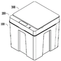
FIG. 1 is a schematic diagram of an embodiment of the present invention.
Fig. 2 is a schematic view showing an opened state of the cover frame assembly in the embodiment of the present invention.
Fig. 3 is a schematic view showing an opened state of the cap assembly in the embodiment of the present invention.
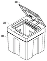
Fig. 4 is a schematic view showing an opened state of the cap assembly in the embodiment of the present invention.
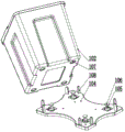
Fig. 5 is a schematic view showing the installation of the weight sensor in the embodiment of the present invention.
Fig. 6 is another schematic view of the installation of a weight sensor in an embodiment of the utility model.
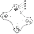
Fig. 7 is a schematic view of a support plate in an embodiment of the utility model.
FIG. 8 is a schematic view of an outer case according to an embodiment of the present invention.
Fig. 9 is a schematic view of the installation of the case assembly and the cover frame assembly in the embodiment of the present invention.
Fig. 10 is a schematic view of a cover frame assembly in an embodiment of the present invention.
Fig. 11 is a schematic view of the assembly of the cover frame assembly and the top cover assembly in the embodiment of the present invention.
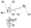
FIG. 12 is a schematic view of a damping wafer and a linear damper in accordance with an embodiment of the present invention.
FIG. 13 is a schematic view of the assembly of the hinge and cover assembly according to an embodiment of the present invention.
The box body assembly 100, the outer box body 101, the inner barrel 102, the lifting handle 103, the support plate 104, the weight sensor 105, the foot pad 106, the positioning groove 107, the guide rib 108, the accommodating groove 109, the vibration induction switch 110 and the magnet 111; the device comprises a cover frame assembly 200, an upper cover 201, a lower shell 202, a cover hole 203, a first hinge 204, a rotary damper 205, a flip motor assembly 206, a linear damper 207, an infrared induction switch 208, a manual switch 209, a reed switch 210, a display panel 211, a rotating shaft 212, a damping pressing sheet 213, a sleeve 214, a linkage plate 215 and a rotating shaft seat 216; the top cover component 300, the hinge support lug 301, the flip gear 302 and the linkage pressing plate 303.
Detailed Description
The utility model is further described with reference to the following figures and examples.
In the embodiment, as shown in fig. 1 to 4, the intelligent waste collecting box is composed of a box body assembly 100, a cover frame assembly 200 and a top cover assembly 300.
As shown in fig. 4, the container assembly 100 includes an outer container 101 and an inner container 102, wherein the inner container 102 is a space for placing garbage bags and wastes, and is provided with a foldable handle 103 for easy removal from the outer container 101.
As shown in fig. 5 to 8, a support plate 104 is disposed at the bottom of the outer box 101 for placing the inner barrel 102, a weight sensor 105 is disposed at each of four corners of the support plate 104, a foot pad 106 covers the upper surface of the weight sensor 105, and four positioning slots 107 are correspondingly disposed at four corners of the bottom of the inner barrel 102, and correspond to the weight sensors 105 one by one. The plurality of weight sensors 105 can accurately weigh the waste, and the weight of the waste can be displayed on the display panel 211 of the cover frame assembly 200 for easy viewing. Furthermore, accurate statistics can be carried out on the weight of the waste, and the requirement of certain specific fields such as medical industry on data acquisition and recording of special garbage is met.
As shown in fig. 5 to 7, the four corners of the supporting plate 104 are provided with vertical guide ribs 108 for limiting the horizontal position of the inner barrel 102 and ensuring the weighing accuracy of the weight sensor 105.
As shown in fig. 7 and 8, the bottom of the outer case 101 is provided with a receiving groove 109 having a shape corresponding to the shape of the support plate 104, so that the support plate 104 can be stably placed in the outer case 101. The support plate 104 and the outer case 101 are further fixed by a plurality of screws.
As shown in fig. 9, the casing of the cover frame assembly 200 includes two parts, i.e., an upper cover 201 and a lower cover 202, constituting a frame-type box structure, in which various components are accommodated, a cover hole 203 is formed in the middle of the frame, and the cover hole 203 is aligned with the inner tub 102 in a downward direction and is engaged with the top cover assembly 300 in an upward direction.
As shown in fig. 9 and 10, the cover frame assembly 200 and the outer case 101 are of a flip structure, a first hinge 204 is disposed between the two, and a rotary damper 205 is provided, so that the cover frame assembly 200 can be opened or closed smoothly by manual operation, and a violent collision can be avoided. The inner tub 102 can be conveniently taken out after the cover frame assembly 200 is opened.
As shown in fig. 11, a flip structure is also employed between the top cover assembly 300 and the cover frame assembly 200, and the direction of the flip is consistent with the cover frame assembly 200, but the opening and closing of the cover is achieved in an automatic manner. After the top cover assembly 300 is automatically opened, garbage can be conveniently put in or a garbage bag can be conveniently taken out.
As shown in fig. 11, the top cover assembly 300 has two hinge support lugs 301, the hinge support lugs 301 are hinged to the cover frame assembly 200 through a rotating shaft 212, one of the hinge support lugs 301 is provided with a flip gear 302 of an integrated structure, the cover frame assembly 200 is provided with a flip motor assembly 206, and an output shaft gear of the flip motor assembly 206 is meshed with the flip gear 302 to realize the flip of the top cover assembly 300.
As shown in fig. 11 and 12, a linear damper 207 and a damping pressing plate 213 are further disposed in the cover frame assembly 200, the damping pressing plate 213 is an extension rod of the linear damper 207, the damping pressing plate 213 is mounted on the rotating shaft 212 through an integrated sleeve 214, the sleeve 214 is further provided with an integrated linkage plate 215, and the linkage plate 215 rotates around the rotating shaft 212 together with the top cover assembly 300. This structure does not function when the cap assembly 300 is opened and functions as a damping buffer when the cap assembly 300 is closed. The positions of the linear damper 207 and the damping pressure plate 213 may be appropriately adjusted and only need to be respectively disposed on the cover frame assembly 200 and the top cover assembly 300. Furthermore, the linear damper 207 may be replaced with another type of damper.
As shown in fig. 12, a rotating shaft seat 216 is fixed to each end of the rotating shaft 212, and the rotating shaft seats 216 are installed inside the cover frame assembly 200 by bolts.
As shown in fig. 13, the top cover assembly 300 is provided with a linkage pressing plate 303 at the hinge lug 301, and the linkage pressing plate 303 corresponds to the linkage plate 215 and is disposed above the linkage plate 215. When the top cover assembly 300 is opened, the linkage pressing plate 303 does not act on the linkage plate 215, and when the top cover assembly 300 is closed, the linkage pressing plate 303 drives the linkage plate 215 to rotate, so that the damping pressing sheet 213 presses the linear damper 207 downwards, and a damping buffering effect is achieved. In addition, the rotating shaft 212 may have a two-step structure, so as to facilitate the installation of the damping sheet 213.
As shown in fig. 9, the box assembly 100 is provided with a vibration sensing switch 110, and the upper cover 201 of the cover frame assembly 200 is provided with an infrared sensing switch 208 and a manual switch 209, which are all used as control elements of the flip motor assembly 206, i.e. a first switch, to achieve automatic opening of the top cover assembly 300. The vibration sensing switch 110 enables kick or touch uncapping, the infrared sensing switch 208 enables proximity sensing uncapping, and the manual switch is in a manual operation mode. One of the three switches can be selected, or a plurality of the three switches can be simultaneously acted. The flip motor assembly 206 performs three actions of rotating to open the cover, stopping for a short time and rotating to close the cover after receiving a signal of a certain switch, and the action control is simple and can be realized by adopting positive and negative alternate pulse signals with zero-crossing point delay, or can be realized by adopting a limit switch, a delay switch or a programming mode. The vibration sensing switch 110 may select one of a spring switch or a ball switch. The infrared sensing switch 208 is composed of an infrared sensing circuit and a voltage sampling comparison circuit, wherein the core elements of the infrared sensing circuit are an infrared transmitting tube and an infrared receiving tube, and the core elements of the voltage sampling comparison circuit are a potentiometer and a general operational amplifier.
As shown in fig. 9, a magnetic induction switch, i.e., a second switch, is further disposed between the box assembly 100 and the cover frame assembly 200, specifically, a magnet 111 disposed on the box assembly 100 and a reed pipe 210 disposed on the cover frame assembly 200. The magnetic induction switch is used for controlling the vibration induction switch 110 and the infrared induction switch 208. Specifically, when the lid frame assembly 200 is turned over and opened relative to the box assembly 100, the reed switch 210 is triggered, that is, the magnetic induction switch is triggered, the vibration induction switch 110 or the infrared induction switch 208 is controlled to be disabled, or the flip motor assembly 206 is directly disconnected, and at this time, even if the lid frame assembly 200 or the box assembly 100 is touched or approached, the top cover assembly 300 cannot be opened, so that the false triggering of the top cover assembly 300 when the lid frame assembly 200 is turned over and taken out to pack garbage can be avoided.
It should be understood that the above-described embodiments of the present invention are merely examples for illustrating the present invention, and are not intended to limit the embodiments of the present invention. Obvious variations or modifications of the present invention are possible within the spirit of the present invention.
Claims (7)
1. The automatic weighing device for the intelligent collecting box of the medical waste treatment block chain system is characterized by comprising an outer box body (101) and an inner barrel (102), wherein a plurality of weight sensors (105) are arranged in the outer box body (101), and the inner barrel (102) is placed on the weight sensors (105).
2. The automatic weighing device of the intelligent collection box of the medical waste treatment block chain system of claim 1, wherein: the bottom of the outer box body (101) is provided with a support plate (104), and four corners of the support plate (104) are respectively provided with one weight sensor (105).
3. The automatic weighing device of the intelligent collection box of the medical waste treatment block chain system of claim 2, wherein: and guide ribs (108) in the vertical direction are arranged at four corners of the support plate (104) and are used for limiting the horizontal position of the inner barrel (102).
4. The automatic weighing device of the intelligent collection box of the medical waste treatment block chain system of claim 2, wherein: the bottom of the outer box body (101) is provided with an accommodating groove (109) which is consistent with the shape of the supporting plate (104).
5. The automatic weighing device of the intelligent collection box of the medical waste treatment block chain system of claim 1, wherein: a foot pad (106) is covered above the weight sensor (105).
6. The automatic weighing device of the intelligent collection box of the medical waste treatment block chain system of claim 1, wherein: and a positioning groove (107) is formed in the inner barrel (102) corresponding to the weight sensor (105).
7. The automatic weighing device of the intelligent collection box of the medical waste treatment block chain system of claim 1, wherein: the inner barrel (102) is provided with a foldable handle (103).
Priority Applications (1)
| Application Number | Priority Date | Filing Date | Title |
|---|---|---|---|
| CN202122189544.5U CN215923330U (en) | 2021-09-10 | 2021-09-10 | Automatic weighing device of intelligent collecting box of medical waste treatment block chain system |
Applications Claiming Priority (1)
| Application Number | Priority Date | Filing Date | Title |
|---|---|---|---|
| CN202122189544.5U CN215923330U (en) | 2021-09-10 | 2021-09-10 | Automatic weighing device of intelligent collecting box of medical waste treatment block chain system |
Publications (1)
| Publication Number | Publication Date |
|---|---|
| CN215923330U true CN215923330U (en) | 2022-03-01 |
Family
ID=80419918
Family Applications (1)
| Application Number | Title | Priority Date | Filing Date |
|---|---|---|---|
| CN202122189544.5U Active CN215923330U (en) | 2021-09-10 | 2021-09-10 | Automatic weighing device of intelligent collecting box of medical waste treatment block chain system |
Country Status (1)
| Country | Link |
|---|---|
| CN (1) | CN215923330U (en) |
Cited By (1)
| Publication number | Priority date | Publication date | Assignee | Title |
|---|---|---|---|---|
| CN115231158A (en) * | 2022-04-18 | 2022-10-25 | 中航西安飞机工业集团股份有限公司 | Dangerous waste placing table and using method |
-
2021
- 2021-09-10 CN CN202122189544.5U patent/CN215923330U/en active Active
Cited By (1)
| Publication number | Priority date | Publication date | Assignee | Title |
|---|---|---|---|---|
| CN115231158A (en) * | 2022-04-18 | 2022-10-25 | 中航西安飞机工业集团股份有限公司 | Dangerous waste placing table and using method |
Similar Documents
| Publication | Publication Date | Title |
|---|---|---|
| EP2025623B1 (en) | Waste container with electrostatically controlled cover | |
| CN215923330U (en) | Automatic weighing device of intelligent collecting box of medical waste treatment block chain system | |
| KR101017284B1 (en) | Collection device of garbage | |
| CN109573412A (en) | A kind of intelligent garbage bin with automatic beam sack function | |
| CN208150222U (en) | A kind of intelligence turning cover dustbin | |
| US20050224496A1 (en) | Trash can receptacle | |
| CN215923328U (en) | Flip induction system of medical waste treatment block chain system intelligent collection box | |
| CN215923329U (en) | Automatic cover turning structure of intelligent collecting box of medical waste treatment block chain system | |
| KR101615322B1 (en) | Compression type garbage can | |
| CN211732617U (en) | Intelligent garbage can | |
| CN208265055U (en) | A kind of anti-overflow dustbin of Compressible | |
| CN215923331U (en) | Intelligent collection box of medical waste treatment block chain system | |
| CN210943227U (en) | Lid of waste classification intelligence case is opened and is removed structure | |
| CN215556152U (en) | Trash can cover equipment | |
| CN213770002U (en) | Intelligent garbage can | |
| CN113619959A (en) | Intelligent collection box of medical waste treatment block chain system | |
| CN210311941U (en) | Intelligent garbage cabinet | |
| TWM577416U (en) | Smart trash can | |
| CN213567832U (en) | Medical multifunctional garbage classification box | |
| CN208199460U (en) | A kind of Mobile medical dustbin | |
| CN208683588U (en) | A kind of integral type Medical waste sorting collecting cart | |
| CN109625674A (en) | A kind of single two-door automatic sensing classification garbage can of popping one's head in | |
| RU134913U1 (en) | Litter bin | |
| JP2022506844A (en) | Trash can with airtight means to prevent stink leaks | |
| CN218008718U (en) | Dining table convenient for throwing garbage |
Legal Events
| Date | Code | Title | Description |
|---|---|---|---|
| GR01 | Patent grant | ||
| GR01 | Patent grant | ||
| TR01 | Transfer of patent right |
Effective date of registration: 20230608 Address after: No.56, lingzhi Road, Xuanwu District, Nanjing City, Jiangsu Province, 210000 Patentee after: Niuge Information Technology (Nanjing) Co.,Ltd. Address before: 210000 rooms 212, 213, 214, 215, 216 and 217, building 3, No. 56, lingzhi Road, Xuanwu District, Nanjing City, Jiangsu Province Patentee before: Jiangsu Yuchi blockchain Technology Research Institute Co.,Ltd. |
|
| TR01 | Transfer of patent right |