CN215897546U - Winding mold capable of automatically adapting to different stator lamination thicknesses - Google Patents
Winding mold capable of automatically adapting to different stator lamination thicknesses Download PDFInfo
- Publication number
- CN215897546U CN215897546U CN202121459894.2U CN202121459894U CN215897546U CN 215897546 U CN215897546 U CN 215897546U CN 202121459894 U CN202121459894 U CN 202121459894U CN 215897546 U CN215897546 U CN 215897546U
- Authority
- CN
- China
- Prior art keywords
- die
- fixing plate
- winding
- die fixing
- rear die
- Prior art date
- Legal status (The legal status is an assumption and is not a legal conclusion. Google has not performed a legal analysis and makes no representation as to the accuracy of the status listed.)
- Active
Links
Images

Abstract
The utility model discloses a winding die capable of automatically adapting to different stator stack thicknesses. The servo motor is connected with a driving wheel through a speed reducer, the driving wheel is connected with a driven wheel belt, the upper end of a middle shaft is provided with a driven wheel, the lower end of the middle shaft is provided with a helical gear, and the middle shaft is arranged on an upper plate through a bearing; a bearing fixing seat supporting threaded shaft is arranged on the upper plate, and two ends of the threaded shaft are respectively in threaded fit with a left-handed threaded sleeve in a front die threaded sleeve fixing seat fixed on a front die fixing plate and a right-handed threaded sleeve in a rear die threaded sleeve fixing seat fixed on a rear die fixing plate; the upper ends of the front die fixing plate and the rear die fixing plate are connected with a guide rail slide block fixed on the upper plate, and the lower ends of the front die fixing plate and the rear die fixing plate are respectively fixed with the winding front die and the winding rear die. The die change process is simplified, the labor cost is saved, and the operation safety is ensured under the condition of die change of the large motor stator.
Description
Technical Field
The utility model belongs to the technical field of electrical machinery, and particularly relates to a winding mold capable of automatically adapting to different stator stack thicknesses on an industrial motor stator winding machine.
Background
Along with the industrial motor electrical machinery field degree of automation is higher and higher, the stator stack thickness variety is more and more changeable, and present industrial motor stator winding wire winding equipment all realizes winding former interval change by manual rotation basically to adapt to the stator of different stack thickness. Its shortcoming lies in that industrial motor stator hole and external diameter size all are greater than other types of motor, and the winding former compares in other motor stator winding former sizes and increases a lot, and it is too big through the artifical mould interval degree of difficulty of adjusting, and security, convenience can not obtain guaranteeing. Meanwhile, the number of the parallel winding is increased, the wire diameter is increased, so that the tension during wire forming is also increased, and after the wire winding is finished, the coil cannot fall into the wire inserting machine head quickly, so that the wire inserting quality and the automation degree of equipment are influenced.
Disclosure of Invention
In order to solve the defects of the prior art, the utility model aims to provide a winding die capable of automatically adapting to different stator stack thicknesses.
The technical scheme of the utility model is as follows: a winding mould automatically adapting to different stator lamination thicknesses is characterized in that a servo motor is connected with a driving wheel through a speed reducer, the driving wheel is connected with a driven wheel belt, a driven wheel is arranged at the upper end of a middle shaft, a helical gear is arranged at the lower end of the middle shaft, and the middle shaft is mounted on an upper plate through a bearing; a bearing fixing seat supporting threaded shaft is arranged on the upper plate, and two ends of the threaded shaft are respectively in threaded fit with a left-handed threaded sleeve in a front die threaded sleeve fixing seat fixed on a front die fixing plate and a right-handed threaded sleeve in a rear die threaded sleeve fixing seat fixed on a rear die fixing plate; the upper ends of the front die fixing plate and the rear die fixing plate are connected with a guide rail slide block fixed on the upper plate, and the lower ends of the front die fixing plate and the rear die fixing plate are respectively fixed with the winding front die and the winding rear die.
Due to the adoption of the working scheme: when the device works, the servo motor realizes the action transmission between the driving wheel and the driven wheel through belt transmission, the driven wheel at the upper end of the die realizes synchronous rotation with the intermediate shaft through the expansion sleeve and realizes the lubricating and guiding functions through the bearing; at the central position, the intermediate shaft and the lower end gear expand tightly to realize synchronous rotation, and the lower end gear is meshed with the helical gear at the intermediate end of the threaded shaft to realize the opening and closing actions of the front and rear winding dies under the action of the left-right threaded sleeve, so that the automatic adjustment of different stacking thicknesses is realized; the winding front die and the winding rear die are connected with a guide rail through a front die fixing plate and a rear die fixing plate, and the guide rail is fixed at the lower end of the upper plate;
has the advantages that: the device satisfies under the wire winding mould wire winding and with the cooperation of rule aircraft nose and accomplish basic function's prerequisite, has further realized the different innovative action of folding thick of automatic adjustment again, has used the gear engagement structure in a flexible way when realizing quick adjustment, and ingenious perfect realization of loaded down with trivial details retooling flow through the optimal design structure has simplified retooling flow, saves the cost of labor, has guaranteed the security of operation under the condition of large-scale motor stator retooling. Meanwhile, after the coil is wound, the coil quickly falls into the machine head through die assembly, so that the production efficiency is improved, the automation degree is improved, the requirement of industrial processing is met, and the coil winding machine has high popularization value.
Description of the drawings: the technical solution of the present invention will be described in detail with reference to the accompanying drawings and the detailed description.
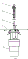
Fig. 1 is a front view of the present invention.
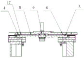
Fig. 2 is a sectional view a-a of fig. 1.
Fig. 3 is a sectional view B-B of fig. 1.
In the figure: 1. the winding machine comprises a winding front die 2, a winding rear die 3, a rear die fixing plate 4, a left-handed screw sleeve 5, a right-handed screw sleeve 6, a front die screw sleeve fixing seat 7, a bearing fixing seat 8, a threaded shaft 9, a helical gear 10, an intermediate shaft 11, a tensioning ring 12, a driving wheel 13, a driven wheel 14, a servo motor 15, an upper plate 16, a front die fixing plate 17 and a rear die screw sleeve fixing seat.
The specific implementation mode is as follows:
the present invention will be described in further detail with reference to the accompanying drawings and specific embodiments.
Referring to fig. 1-3, a winding die that automatically accommodates different stator stack thicknesses:
the servo motor 14 is connected with a driving wheel 12 through a speed reducer, the driving wheel 12 is in belt connection with a driven wheel 13, the driven wheel 13 is arranged at the upper end of a middle shaft 10, a helical gear 9 is arranged at the lower end of the middle shaft 10, and the middle shaft 10 is installed on an upper plate 15 through a bearing; a bearing fixing seat 7 is arranged on the upper plate 15 to support a threaded shaft 8, and two ends of the threaded shaft 8 are respectively in threaded fit with a left-handed thread bush 4 in a front die thread bush fixing seat 17 fixed on a front die fixing plate 16 and a right-handed thread bush thread 5 in a rear die thread bush fixing seat 6 fixed on a rear die fixing plate 3; the upper ends of the front die fixing plate 16 and the rear die fixing plate 3 are connected with a guide rail slide block fixed on the upper plate 15, and the lower ends of the front die fixing plate 16 and the rear die fixing plate 3 are respectively fixed with the winding front die 1 and the winding rear die 2.
The power device servo motor 14 is matched with the driving wheel 12 and the speed reducer for use to provide power, and transmits the power to the driven wheel 13 through a belt; the driven wheel 13 is matched with the intermediate shaft 10 through an expansion sleeve to realize synchronous rotation; the lower end intermediate shaft 10 is locked by the expansion sleeve again to realize synchronous rotation with a straight gear at the center, the helical gear 9 is meshed with the straight gear to realize rotation of the threaded shaft 8, and the left end and the right end of the threaded shaft 8 are respectively provided with left-handed and right-handed reverse threads, so that simultaneous opening and closing actions of the front winding die and the rear winding die are realized;
in the automatic thickness-adjusting winding device, a winding front die 1 and a winding rear die 2 are fixed on a front die fixing plate 16, a rear die fixing plate 3 is connected with a guide rail sliding block, and a guide rail is fixed on an upper plate; the threaded shaft 8 is connected with the front die fixing plate 16 and the rear die fixing plate 3 through the threaded sleeve fixing seat 6 to realize the continuous action of automatically adjusting the stacking thickness.
The above embodiments are not intended to limit the present invention, and the present invention is not limited to the above examples, and those skilled in the art may make variations, modifications, additions or substitutions within the technical scope of the present invention.
Claims (1)
1. The utility model provides an automatic adapt to different stator and fold thick wire winding mould which characterized in that: the servo motor (14) is connected with the driving wheel (12) through a speed reducer, the driving wheel (12) is in belt connection with the driven wheel (13), the driven wheel (13) is arranged at the upper end of the intermediate shaft (10), the helical gear (9) is arranged at the lower end of the intermediate shaft (10), and the intermediate shaft (10) is installed on the upper plate (15) through a bearing; a bearing fixing seat (7) is arranged on the upper plate (15) to support a threaded shaft (8), and two ends of the threaded shaft (8) are respectively in threaded fit with a left-handed thread sleeve (4) in a front die thread sleeve fixing seat (17) fixed on a front die fixing plate (16) and a right-handed thread sleeve thread (5) in a rear die thread sleeve fixing seat (6) fixed on a rear die fixing plate (3); the upper ends of the front die fixing plate (16) and the rear die fixing plate (3) are connected with a guide rail slide block fixed on the upper plate (15), and the lower ends of the front die fixing plate (16) and the rear die fixing plate (3) are respectively fixed with the winding front die (1) and the winding rear die (2).
Priority Applications (1)
| Application Number | Priority Date | Filing Date | Title |
|---|---|---|---|
| CN202121459894.2U CN215897546U (en) | 2021-06-30 | 2021-06-30 | Winding mold capable of automatically adapting to different stator lamination thicknesses |
Applications Claiming Priority (1)
| Application Number | Priority Date | Filing Date | Title |
|---|---|---|---|
| CN202121459894.2U CN215897546U (en) | 2021-06-30 | 2021-06-30 | Winding mold capable of automatically adapting to different stator lamination thicknesses |
Publications (1)
| Publication Number | Publication Date |
|---|---|
| CN215897546U true CN215897546U (en) | 2022-02-22 |
Family
ID=80562108
Family Applications (1)
| Application Number | Title | Priority Date | Filing Date |
|---|---|---|---|
| CN202121459894.2U Active CN215897546U (en) | 2021-06-30 | 2021-06-30 | Winding mold capable of automatically adapting to different stator lamination thicknesses |
Country Status (1)
| Country | Link |
|---|---|
| CN (1) | CN215897546U (en) |
Cited By (1)
| Publication number | Priority date | Publication date | Assignee | Title |
|---|---|---|---|---|
| CN113346693A (en) * | 2021-06-30 | 2021-09-03 | 山东中际智能装备有限公司 | Winding mold capable of automatically adapting to different stator lamination thicknesses |
-
2021
- 2021-06-30 CN CN202121459894.2U patent/CN215897546U/en active Active
Cited By (1)
| Publication number | Priority date | Publication date | Assignee | Title |
|---|---|---|---|---|
| CN113346693A (en) * | 2021-06-30 | 2021-09-03 | 山东中际智能装备有限公司 | Winding mold capable of automatically adapting to different stator lamination thicknesses |
Similar Documents
| Publication | Publication Date | Title |
|---|---|---|
| CN215897546U (en) | Winding mold capable of automatically adapting to different stator lamination thicknesses | |
| CN102069136B (en) | Numerically controlled complete equipment for manufacturing deformed springs and torsion springs | |
| CN112536348B (en) | High-efficient abnormal shape make-up machine | |
| CN201780934U (en) | High-precision fixed-length wire feeding device with pair wheels | |
| CN212608719U (en) | Full-automatic slitter edge coiling mechanism | |
| CN201603823U (en) | Torsion spring device | |
| CN113346693A (en) | Winding mold capable of automatically adapting to different stator lamination thicknesses | |
| KR101479546B1 (en) | Straight feed tools for Spring forming machine | |
| CN110102633A (en) | A kind of auxiliary mould for side positioning | |
| CN203171119U (en) | Wire feeding mechanism for argon arc welding machine | |
| CN205415966U (en) | Automatic blank remedying machine | |
| CN205915126U (en) | Mesopore grinding machine device | |
| CN202199828U (en) | Four-crank rotary flying shear | |
| CN211661257U (en) | Tapping device for machining | |
| CN209477155U (en) | Pier nose bending and molding all-in-one machine | |
| CN109616940B (en) | Automatic binding machine for wiring harness | |
| CN208132448U (en) | A kind of clamping device for machining | |
| CN100408258C (en) | Integral screw blade winding and pressing formation apparatus and process | |
| CN111403170A (en) | Double-rotation winding device for electronic element | |
| CN218134526U (en) | Automatic feeding device of nut processing machine tool | |
| CN202137449U (en) | Broaching device | |
| CN2564280Y (en) | Punching and threading machine | |
| CN201052590Y (en) | Grinding machine trip-stop mechanism | |
| CN219274101U (en) | Automatic equipment for producing spring line | |
| CN216037825U (en) | High-speed knitting machine for producing electronic passport anti-counterfeiting line |
Legal Events
| Date | Code | Title | Description |
|---|---|---|---|
| GR01 | Patent grant | ||
| GR01 | Patent grant |