CN215878065U - Foldable impact crushing device - Google Patents
Foldable impact crushing device Download PDFInfo
- Publication number
- CN215878065U CN215878065U CN202122135654.3U CN202122135654U CN215878065U CN 215878065 U CN215878065 U CN 215878065U CN 202122135654 U CN202122135654 U CN 202122135654U CN 215878065 U CN215878065 U CN 215878065U
- Authority
- CN
- China
- Prior art keywords
- hydraulic
- hinged
- pump station
- support
- pushing block
- Prior art date
- Legal status (The legal status is an assumption and is not a legal conclusion. Google has not performed a legal analysis and makes no representation as to the accuracy of the status listed.)
- Active
Links
Images


Abstract
The utility model belongs to the technical field of underground development equipment of coal mines, and particularly relates to a foldable impact crushing device. A foldable impact crushing device comprises a crushing assembly, an oil tank pump station part, a control part, a hydraulic system, a scraper conveyor, a pushing block, a hydraulic support and a reversed loader; the crushing assembly is arranged on the pushing block; the oil tank pump station part is arranged on the reversed loader; the operating part is arranged on the side surface of the hydraulic bracket; the hydraulic system is arranged on the pump station part of the oil tank, and the scraper conveyor is arranged below the hydraulic support; the front end of the pushing block is fixedly connected with the scraper conveyor, the rear end of the pushing block is hinged with the hydraulic support, and the pushing block is pushed forwards and backwards under the action of an oil cylinder of the hydraulic support; the reversed loader is in lap joint with the scraper conveyor, and materials transported on the scraper conveyor are transferred out. The utility model effectively solves the problems of low efficiency of the coal mine fully-mechanized mining face crushing operation, high labor intensity of workers, poor safety, low mechanization degree and the like.
Description
Technical Field
The utility model belongs to the technical field of underground development equipment of coal mines, and particularly relates to a foldable impact crushing device.
Background
With the progress of times and the development of social economy, the coal industry in China develops rapidly, the mechanization level of underground coal mines is continuously improved, particularly the mechanized mining surface is basically mechanized, when coal cutting of a coal mining machine is overlarge, the coal blocks are conveyed to a reversed loader through a scraper conveyor and need to be manually crushed when meeting a blockage, at the moment, the scraper conveyor needs to be locked after power failure, and the overlarge coal blocks are manually crushed on the scraper conveyor by using a single upright post. The traditional manual operation mode is extremely unsafe, the labor intensity of workers is greatly enhanced, the efficiency and the quality of crushing operation are reduced, and meanwhile, the continuity of conveying is greatly influenced by frequent starting and locking of the unit.
SUMMERY OF THE UTILITY MODEL
The utility model aims to provide a foldable impact crushing device which effectively solves the problems of low efficiency, high labor intensity of workers, poor safety, low mechanization degree and the like of the crushing operation of a fully mechanized mining surface of a coal mine.
In order to achieve the purpose, the utility model adopts the technical scheme that:
a foldable impact crushing device comprises a crushing assembly, an oil tank pump station part, a control part, a hydraulic system, a scraper conveyor, a pushing block, a hydraulic support and a reversed loader; the crushing assembly is arranged on the pushing block; the oil tank pump station part is arranged on the reversed loader; the operating part is arranged on the side surface of the hydraulic bracket; the hydraulic system is arranged on the pump station part of the oil tank, and the scraper conveyor is arranged below the hydraulic support; the front end of the pushing block is fixedly connected with the scraper conveyor, the rear end of the pushing block is hinged with the hydraulic support, and the pushing block is pushed forwards and backwards under the action of an oil cylinder of the hydraulic support; the reversed loader is in lap joint with the scraper conveyor, and materials transported on the scraper conveyor are transferred out.
The crushing assembly consists of a rotary fixing seat, a hydraulic swing motor, a connecting disc, a rotary seat, a lifting arm supporting oil cylinder, a shaking rod adjusting oil cylinder, a lifting arm, a shaking rod, a crushing hammer adjusting oil cylinder, a rocker I, a rocker II and a crushing hammer; the rotary fixed seat is fixed on the pushing block; the hydraulic swing motor is fixedly connected with the pushing block and the rotary fixing seat through the connecting disc respectively, a rotary shaft of the hydraulic swing motor rotates to drive the crushing assembly to rotate to the position above the scraper conveyor for crushing operation, and after the operation is finished, the crushing assembly rotates leftwards or rightwards by 90 degrees and is retracted to the position below the hydraulic support; the bottom of the rotary seat is fixed with a rotating shaft of the hydraulic swing motor; one end of the lifting arm is hinged to the rotary seat, and the other end of the lifting arm is hinged to the shaking rod; the lifting arm supporting oil cylinders are arranged symmetrically left and right, one end of the cylinder body is hinged with the connecting lug at the front end of the rotary seat, one end of the telescopic rod is hinged with the connecting lug at the outer side of the lifting arm, and the height of the lifting arm is controlled by the expansion of the lifting arm supporting oil cylinder; one end of the cylinder body of the shaking rod adjusting oil cylinder is hinged to the lifting arm, one end of a telescopic rod of the shaking rod adjusting oil cylinder is hinged to the rear end of the shaking rod, and the shaking rod adjusts the position of the telescopic adjusting shaking rod of the oil cylinder; the quartering hammer is articulated with the front end of trembleing the pole, the cylinder body one end of quartering hammer adjustment hydro-cylinder articulates in the top of trembleing the pole, and its telescopic link one end is articulated with the one end of rocker I, rocker II, and the other end of rocker I is articulated with trembleing the pole lateral surface, and the other end of rocker II is articulated with the quartering hammer to through the flexible of quartering hammer adjustment hydro-cylinder, cooperation rocker I, II actions of rocker, drive the quartering hammer and stretch out and withdraw.
The oil tank pump station part consists of a shield bottom plate, a pump station shield, an oil tank part and a pump station part; the oil tank part and the pump station part are arranged on the shield bottom plate in parallel, the oil tank part is used for storing hydraulic oil required by the whole hydraulic system, and the pump station part provides power for the hydraulic system; the pump station guard shield is installed above the pump station portion.
The pump station part consists of a plunger pump, a pump bracket, a pump side coupler, a speed reducer bracket, a motor side coupler, a motor bracket and a hydraulic motor; the shell of the plunger pump is arranged on the pump bracket, and the shaft end of the plunger pump is coupled with the pump side coupler; the shell of the speed reducer is fixed on a speed reducer support, the left shaft end of the speed reducer is connected with a pump side coupling, and the right shaft end of the speed reducer is connected with a motor side coupling; the shell of the hydraulic motor is fixed on the motor support, the shaft end of the hydraulic motor is coupled with the coupler, and the bottom ends of the pump support, the reducer support and the motor support are all fixed on the shield bottom plate and are arranged in a left-middle-right mode; the hydraulic motor uses the emulsion as a power source, and the hydraulic motor works to drive the speed reducer to operate, so that the plunger pump is driven to provide power for the oil tank pump station part.
The operation part consists of a proportional multi-way valve, an operation frame and a pressure gauge; the proportional multi-way valve is installed on the operation frame, and the pressure gauge is installed on the outer side of the operation frame and used for displaying the pressure value of the hydraulic system.
The foldable impact crushing device adopting the technical scheme is suitable for crushing operation in a narrow space below a fully mechanized mining face hydraulic support. The crushing assembly is fixed on the pushing block of the hydraulic support, the whole crushing assembly can rotate by 0-180 degrees by using a hydraulic swing motor, wherein a lifting arm is hinged with an adjusting oil cylinder, a crushing hammer, a rocker, a shaking rod and a crushing hammer adjusting oil cylinder are hinged with each other, the height and the impact angle of the crushing hammer can be flexibly adjusted under the drive of each adjusting oil cylinder, the farthest rock breaking distance can reach 2600mm, and the crushing assembly has the characteristics of large working range, high working safety and efficiency, low labor intensity of workers and the like, and fully ensures the transportation continuity of the reversed loader; after the crushing operation is completed, the device is rotated by 90 degrees leftwards or rightwards and placed under a hydraulic support, then the device is retracted and folded, the minimum length and width after folding are 2400mm and 560mm, the height is 2400mm, the size of the device in a non-operation state is greatly reduced, and the narrow space under the hydraulic support is reasonably utilized. In addition, the oil tank pump station part of the device is fixed at a position far away from a crushing site, so that a power source can be effectively protected, and the reliability of a hydraulic system is improved; meanwhile, the control part can be arranged at a position with a wide broken visual field according to the field condition, the operation is convenient, the adjustment is flexible, and the safety performance is high.
The hydraulic system comprises a hydraulic pump station, a proportional multi-way valve, execution oil cylinders, a rotary driving device, breaking hammers, a pressure gauge and the like, the hydraulic system takes emulsion as a power source, utilizes the emulsion pump station which is prepared on the fully-mechanized mining surface to be matched with a speed reducer to drive a plunger pump to run, and supplies high-pressure oil to each execution oil cylinder and each breaking hammer through the proportional multi-way valve respectively, so that the actions of lifting and integral rotation of a breaking assembly, adjustment of the breaking hammers and the like can be completed, the location of the breaking position of the breaking hammer is realized, and the breaking operation is further realized. The device takes high-pressure oil as a power source, the maximum diameter of the crushed carbon block can reach 1400mm, and the device has the advantages of high crushing speed, high impact efficiency, low noise and the like.
Compared with the prior equipment, the utility model has the following advantages:
1. the pump station hydraulic motor takes emulsion as a power source, utilizes the existing emulsion pump station of a fully mechanized mining face and is matched with the speed reducer to provide power for the hydraulic oil pump station, so that the connection is quick and convenient, and the trouble of cable dragging of a unit is avoided;
2. the utility model has compact structure, can realize flexible extension, rotation and folding under the condition of not influencing the work of the hydraulic support, and meets the actual crushing requirement;
3. the position of the operating platform can be fixed according to the site, so that the visual field of operators is ensured, and the safety of the operators is also ensured;
4. the utility model adopts the imported hydraulic breaking hammer to operate, has high breaking working efficiency and fully ensures the continuous transportation of the reversed loader;
5. the hydraulic system of the utility model adopts a load-sensitive control system, thereby reducing the energy consumption, avoiding the possibility of thermal failure of the system and greatly prolonging the service life of the sealing element.
Drawings
FIG. 1 is a schematic structural view of the present utility mechanism;
FIG. 2 is a top view of FIG. 1;
FIG. 3 is a schematic view of the crushing assembly of FIG. 1;
FIG. 4 is a schematic diagram of the pumping station portion of the oil tank of FIG. 2;
FIG. 5 is a top view of FIG. 4;
FIG. 6 is a schematic diagram of the pump station portion of FIG. 5;
fig. 7 is a schematic structural view of the manipulation part of fig. 1.
Detailed Description
As shown in fig. 1 and fig. 2, the foldable impact crusher of the present embodiment includes a crushing assembly 1, an oil tank pump station portion 2, an operation portion 3, a hydraulic system 4, a scraper conveyor 5, a pushing block 6, a hydraulic support 7, and a reversed loader 8; the crushing assembly 1 is arranged on the pushing block 6; the oil tank pump station part 2 is arranged on the reversed loader 8; the operating part 3 is arranged on the side surface of the hydraulic bracket 7; the hydraulic system 4 is arranged on the oil tank pump station part 2, and the scraper conveyor 5 is arranged below the hydraulic support 7; the front end of the pushing block 6 is fixedly connected with the scraper conveyor 5, the rear end of the pushing block is hinged with the hydraulic support 7, and the pushing block 6 is pushed forwards and backwards under the action of an oil cylinder of the hydraulic support 7; the reversed loader 8 is in lap joint with the scraper conveyor 5 and transports the materials transported on the scraper conveyor 5.
As shown in fig. 3, the crushing assembly 1 is composed of a rotary fixing seat 1-1, a hydraulic swing motor 1-2, a connecting disc 1-3, a rotary seat 1-4, a lifting arm supporting oil cylinder 1-5, a shaking rod adjusting oil cylinder 1-6, a lifting arm 1-7, a shaking rod 1-8, a crushing hammer adjusting oil cylinder 1-9, a rocker I1-10, a rocker II 1-11 and a crushing hammer 1-12; the rotary fixed seat 1-1 is fixed on the pushing block 6; the hydraulic swing motor 1-2 is fixedly connected with the pushing block 6 and the rotary fixing seat 1-1 through the connecting disc 1-3 respectively, a rotating shaft of the hydraulic swing motor 1-2 rotates to drive the crushing assembly 1 to rotate to the position above the scraper conveyor 5 for crushing operation, and after the operation is finished, the crushing assembly 1 rotates leftwards or rightwards by 90 degrees and is retracted to the position below the hydraulic support; the bottom of the rotary seat 1-4 is fixed with a rotary shaft of the hydraulic swing motor 1-2; one end of the lifting arm 1-7 is hinged on the rotary seat 1-4, and the other end is hinged with the shaking rod 1-8; the lifting arm supporting oil cylinders 1-5 are arranged symmetrically left and right, one end of the cylinder body is hinged with the connecting lug at the front end of the rotary seat 1-4, one end of the telescopic rod is hinged with the connecting lug at the outer side of the lifting arm 1-7, and the height of the lifting arm 1-7 is controlled by the extension and retraction of the lifting arm supporting oil cylinders 1-5; one end of a cylinder body of the shaking rod adjusting oil cylinder 1-6 is hinged on the lifting arm 1-7, one end of a telescopic rod of the shaking rod adjusting oil cylinder is hinged with the rear end of the shaking rod 1-8, and the shaking rod adjusts the position of the shaking rod 1-8 by the expansion of the oil cylinder 1-6; the breaking hammer 1-12 is hinged with the front end of the shaking rod 1-8, one end of a cylinder body of the breaking hammer adjusting oil cylinder 1-9 is hinged above the shaking rod 1-8, one end of a telescopic rod of the breaking hammer adjusting oil cylinder is hinged with one end of a rocker I1-10 and one end of a rocker II 1-11, the other end of the rocker I1-10 is hinged with the outer side face of the shaking rod 1-8, the other end of the rocker II 1-11 is hinged with the breaking hammer 1-12, and the breaking hammer adjusting oil cylinder 1-9 stretches and retracts to drive the breaking hammer 1-12 to stretch out and retract in cooperation with actions of the rocker I1-10 and the rocker II 1-11, so that the breaking assembly 1 is adjusted more flexibly.
As shown in fig. 4 and 5, the oil tank pump station part 2 is composed of a shield bottom plate 2-1, a pump station shield 2-2, an oil tank part 2-3 and a pump station part 2-4; the oil tank part 2-3 and the pump station part 2-4 are arranged on the shield bottom plate 2-1 in parallel, the oil tank part 2-3 is used for storing hydraulic oil required by the whole hydraulic system 4, and the pump station part 2-4 provides power for the hydraulic system 4; the pump station shield 2-2 is arranged above the pump station part 2-4 and can prevent collision and damage.
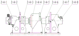
As shown in fig. 6, the pump station part 2-4 consists of a plunger pump 2-4-1, a pump support 2-4-2, a pump side coupling 2-4-3, a speed reducer 2-4-4, a speed reducer support 2-4-5, a motor side coupling 2-4-6, a motor support 2-4-7 and a hydraulic motor 2-4-8; the shell of the plunger pump 2-4-1 is arranged on the pump bracket 2-4-2, and the shaft end of the plunger pump 2-4-1 is coupled with the pump side coupler 2-4-3; the shell of the speed reducer 2-4-4 is fixed on the speed reducer support 2-4-5, the left shaft end of the speed reducer 2-4-4 is connected with the pump side coupling 2-4-3, and the right shaft end of the speed reducer 2-4-4 is connected with the motor side coupling 2-4-6; the shell of the hydraulic motor 2-4-8 is fixed on the motor support 2-4-7, the shaft end of the hydraulic motor 2-4-8 is coupled with the coupling 2-4-6, the bottom ends of the pump support 2-4-2, the reducer support 2-4-5 and the motor support 2-4-7 are all fixed on the shield bottom plate 2-1 and are arranged in a left-middle-right manner; the hydraulic motor 2-4-8 takes emulsion as a power source, and the hydraulic motor 2-4-8 works to drive the speed reducer 2-4-4 to rotate, so that the plunger pump 2-4-1 is driven to provide power for the oil tank pump station part 2.
As shown in fig. 7, the operation part 3 is composed of a proportional multi-way valve 3-1, an operation frame 3-2 and a pressure gauge 3-3; the proportional multi-way valve 3-1 is arranged on the operating frame 3-2, so that the requirement that a plurality of executing elements work simultaneously can be met; the pressure gauge 3-3 is arranged on the outer side of the operating frame 3-2 and used for displaying the pressure value of the hydraulic system 4.
Claims (5)
1. A foldable impact crushing device is characterized in that: the device comprises a crushing assembly (1), an oil tank pump station part (2), a control part (3), a hydraulic system (4), a scraper conveyor (5), a pushing block (6), a hydraulic support (7) and a reversed loader (8); the crushing assembly (1) is arranged on the pushing block (6); the oil tank pump station part (2) is arranged on the reversed loader (8); the operating part (3) is arranged on the side surface of the hydraulic support (7); the hydraulic system (4) is arranged on the oil tank pump station part (2), and the scraper conveyor (5) is arranged below the hydraulic support (7); the front end of the pushing block (6) is fixedly connected with the scraper conveyor (5), the rear end of the pushing block is hinged with the hydraulic support (7), and the pushing block (6) is pushed forwards and backwards under the action of an oil cylinder of the hydraulic support (7); elevating conveyor (8) and scraper conveyor (5) overlap joint are transported away the material of transporting on scraper conveyor (5).
2. A foldable impact crusher as claimed in claim 1, wherein: the crushing assembly (1) consists of a rotary fixed seat (1-1), a hydraulic swing motor (1-2), a connecting disc (1-3), a rotary seat (1-4), a lifting arm supporting oil cylinder (1-5), a shaking rod adjusting oil cylinder (1-6), a lifting arm (1-7), a shaking rod (1-8), a crushing hammer adjusting oil cylinder (1-9), a rocker I (1-10), a rocker II (1-11) and a crushing hammer (1-12); the rotary fixing seat (1-1) is fixed on the pushing block (6); the hydraulic swing motor (1-2) is fixedly connected with the pushing block (6) and the rotary fixing seat (1-1) through the connecting disc (1-3), a rotating shaft of the hydraulic swing motor (1-2) rotates to drive the crushing assembly (1) to rotate to the position above the scraper conveyor (5) for crushing operation, and after the operation is completed, the crushing assembly (1) rotates leftwards or rightwards for 90 degrees and is retracted to the position below the hydraulic support; the bottom of the rotary seat (1-4) is fixed with a rotating shaft of the hydraulic swing motor (1-2); one end of the lifting arm (1-7) is hinged on the rotary seat (1-4), and the other end is hinged with the shaking rod (1-8); the lifting arm supporting oil cylinders (1-5) are arranged symmetrically left and right, one end of the cylinder body is hinged with the connecting lug at the front end of the rotary seat (1-4), one end of the telescopic rod is hinged with the connecting lug at the outer side of the lifting arm (1-7), and the height of the lifting arm (1-7) is controlled by the extension and retraction of the lifting arm supporting oil cylinders (1-5); one end of a cylinder body of the shaking rod adjusting oil cylinder (1-6) is hinged to the lifting arm (1-7), one end of a telescopic rod of the shaking rod adjusting oil cylinder is hinged to the rear end of the shaking rod (1-8), and the position of the shaking rod (1-8) is adjusted by the stretching of the shaking rod adjusting oil cylinder (1-6); the breaking hammer (1-12) is hinged with the front end of the shaking rod (1-8), one end of a cylinder body of the breaking hammer adjusting oil cylinder (1-9) is hinged above the shaking rod (1-8), one end of a telescopic rod of the breaking hammer adjusting oil cylinder is hinged with one end of a rocker I (1-10) and one end of a rocker II (1-11), the other end of the rocker I (1-10) is hinged with the outer side face of the shaking rod (1-8), the other end of the rocker II (1-11) is hinged with the breaking hammer (1-12), and the breaking hammer (1-12) is driven to extend and retract by the stretching of the breaking hammer adjusting oil cylinder (1-9) in cooperation with the actions of the rocker I (1-10) and the rocker II (1-11).
3. A foldable impact crusher as claimed in claim 1, wherein: the oil tank pump station part (2) consists of a shield bottom plate (2-1), a pump station shield (2-2), an oil tank part (2-3) and a pump station part (2-4); the oil tank part (2-3) and the pump station part (2-4) are arranged on the shield bottom plate (2-1) in parallel, the oil tank part (2-3) is used for storing hydraulic oil required by the whole hydraulic system (4), and the pump station part (2-4) provides power for the hydraulic system (4); the pump station shield (2-2) is arranged above the pump station part (2-4).
4. A foldable impact crusher as claimed in claim 3, wherein: the pump station part (2-4) consists of a plunger pump (2-4-1), a pump support (2-4-2), a pump side coupler (2-4-3), a speed reducer (2-4-4), a speed reducer support (2-4-5), a motor side coupler (2-4-6), a motor support (2-4-7) and a hydraulic motor (2-4-8); the shell of the plunger pump (2-4-1) is arranged on the pump bracket (2-4-2), and the shaft end of the plunger pump (2-4-1) is coupled with the pump side coupler (2-4-3); the shell of the speed reducer (2-4-4) is fixed on the speed reducer support (2-4-5), the left shaft end of the speed reducer (2-4-4) is connected with the pump side coupling (2-4-3), and the right shaft end of the speed reducer (2-4-4) is connected with the motor side coupling (2-4-6); the shell of the hydraulic motor (2-4-8) is fixed on the motor support (2-4-7), the shaft end of the hydraulic motor (2-4-8) is coupled with the shaft coupler (2-4-6), and the bottom ends of the pump support (2-4-2), the reducer support (2-4-5) and the motor support (2-4-7) are all fixed on the shield bottom plate (2-1) and are arranged in a left-middle-right mode; the hydraulic motor (2-4-8) takes emulsion as a power source, and the hydraulic motor (2-4-8) works to drive the speed reducer (2-4-4) to operate, so that the plunger pump (2-4-1) is driven to provide power for the oil tank pump station part (2).
5. A foldable impact crusher as claimed in claim 1, wherein: the operation part (3) consists of a proportional multi-way valve (3-1), an operation frame (3-2) and a pressure gauge (3-3); the proportional multi-way valve (3-1) is installed on the operating frame (3-2), and the pressure gauge (3-3) is installed on the outer side of the operating frame (3-2) and used for displaying the pressure value of the hydraulic system (4).
Priority Applications (1)
| Application Number | Priority Date | Filing Date | Title |
|---|---|---|---|
| CN202122135654.3U CN215878065U (en) | 2021-09-06 | 2021-09-06 | Foldable impact crushing device |
Applications Claiming Priority (1)
| Application Number | Priority Date | Filing Date | Title |
|---|---|---|---|
| CN202122135654.3U CN215878065U (en) | 2021-09-06 | 2021-09-06 | Foldable impact crushing device |
Publications (1)
| Publication Number | Publication Date |
|---|---|
| CN215878065U true CN215878065U (en) | 2022-02-22 |
Family
ID=80503490
Family Applications (1)
| Application Number | Title | Priority Date | Filing Date |
|---|---|---|---|
| CN202122135654.3U Active CN215878065U (en) | 2021-09-06 | 2021-09-06 | Foldable impact crushing device |
Country Status (1)
| Country | Link |
|---|---|
| CN (1) | CN215878065U (en) |
Cited By (2)
| Publication number | Priority date | Publication date | Assignee | Title |
|---|---|---|---|---|
| CN114408465A (en) * | 2022-02-25 | 2022-04-29 | 宁夏天地奔牛实业集团有限公司 | Chute system of scraper conveyor |
| CN115121315A (en) * | 2022-08-30 | 2022-09-30 | 山西晋煤集团技术研究院有限责任公司 | Impact rock crushing device for fully mechanized coal mining face |
-
2021
- 2021-09-06 CN CN202122135654.3U patent/CN215878065U/en active Active
Cited By (3)
| Publication number | Priority date | Publication date | Assignee | Title |
|---|---|---|---|---|
| CN114408465A (en) * | 2022-02-25 | 2022-04-29 | 宁夏天地奔牛实业集团有限公司 | Chute system of scraper conveyor |
| CN114408465B (en) * | 2022-02-25 | 2024-02-06 | 宁夏天地奔牛实业集团有限公司 | Chute system of scraper conveyor |
| CN115121315A (en) * | 2022-08-30 | 2022-09-30 | 山西晋煤集团技术研究院有限责任公司 | Impact rock crushing device for fully mechanized coal mining face |
Similar Documents
| Publication | Publication Date | Title |
|---|---|---|
| CN215878065U (en) | Foldable impact crushing device | |
| WO2009155776A1 (en) | A dilling, loading, transporting and anchoring integration machine for laneway in coal mine | |
| CN110318672B (en) | Multifunctional rock roadway drilling and anchoring integrated machine for coal mine | |
| CN111411655A (en) | Multifunctional roadway maintenance repairing machine | |
| CN102168558A (en) | Self-walking lifting full-hydraulic auger coal mining machine | |
| CN103790591A (en) | Comprehensive mechanized impact type rock tunneling machine | |
| CN110242294B (en) | Dual-drive telescopic drum cutting mechanism for tunneling and anchoring integrated machine | |
| CN207229098U (en) | A kind of coalcutter breaker | |
| CN112610271B (en) | Drilling tank slurry backfilling device and method for coal mining subsidence area treatment | |
| CN2900787Y (en) | Small coal mine tunnel tunnelling machine | |
| CN109611092A (en) | A kind of mining full height coalcutter and coal-mining method | |
| CN204152434U (en) | A kind of transhipment anchor shaft anchor cable six arm drill carriage | |
| CN212177137U (en) | Rectangular heading machine | |
| CN201277043Y (en) | Multifunctional bottom loader | |
| CN205955742U (en) | High -efficient quick stone drifting machine | |
| CN103216226A (en) | Water-jet cutting and impacting mining machine | |
| CN202745866U (en) | Water-jet cutting and impacting mining machine | |
| CN204609879U (en) | A kind of pick anchor all-in-one | |
| CN202745867U (en) | Coal mining machine with water-jet cutter | |
| CN204152431U (en) | A kind of transhipment anchor shaft anchor cable eight arm drill carriage | |
| CN2828313Y (en) | Coal mine tunnelling machine | |
| CN111119884A (en) | Fully mechanized coal mining equipment capable of increasing lump coal proportion and corresponding coal mining process | |
| CN203531901U (en) | Multi-functional hydraulic rock drilling shoveling device | |
| CN201407040Y (en) | Automatic coal shovel | |
| CN207812252U (en) | A kind of smashing device in cement flooring for building |
Legal Events
| Date | Code | Title | Description |
|---|---|---|---|
| GR01 | Patent grant | ||
| GR01 | Patent grant |