CN215817689U - Permanent magnet rotor assembly - Google Patents
Permanent magnet rotor assembly Download PDFInfo
- Publication number
- CN215817689U CN215817689U CN202122066418.0U CN202122066418U CN215817689U CN 215817689 U CN215817689 U CN 215817689U CN 202122066418 U CN202122066418 U CN 202122066418U CN 215817689 U CN215817689 U CN 215817689U
- Authority
- CN
- China
- Prior art keywords
- permanent magnet
- grooves
- rotor assembly
- embedded
- squirrel cage
- Prior art date
- Legal status (The legal status is an assumption and is not a legal conclusion. Google has not performed a legal analysis and makes no representation as to the accuracy of the status listed.)
- Active
Links
Images


Abstract
The utility model discloses a permanent magnet rotor assembly, which comprises a rotor core, a permanent magnet rotor assembly and a rotor core, wherein the rotor core is integrally installed and connected with a rotating shaft; the rotor core is provided with a plurality of permanent magnet embedding grooves distributed at intervals circumferentially and a plurality of squirrel cage grooves distributed at intervals circumferentially, wherein the squirrel cage grooves are positioned on the periphery of the permanent magnet embedding grooves, permanent magnets are embedded in the permanent magnet embedding grooves, and squirrel cage guide bars are embedded in the squirrel cage grooves; the permanent magnet embedded groove comprises a left permanent magnet embedded groove unit and a right permanent magnet embedded groove unit which are connected into a V shape; the utility model not only can enable the applied permanent magnet synchronous motor to have the advantages of a three-phase asynchronous induction motor and a permanent magnet synchronous motor, but also can effectively improve the salient pole magnetic gathering effect of the motor, simultaneously enables the motor to have more excellent pull-in torque and step-out torque, and reduces the resistance of a rotor.
Description
Technical Field
The utility model belongs to the field of motors, and particularly relates to a permanent magnet rotor assembly.
Background
At present, in the industries of environment-friendly fans, water pumps, speed reducers and the like, a motor mainly applied is mainly a three-phase asynchronous induction motor. With the rapid development of electronic appliances and artificial intelligence in recent years, a permanent magnet synchronous motor has been introduced into some products, and compared with a three-phase asynchronous induction motor, the permanent magnet synchronous motor has the advantages of high efficiency, high power density and the like.
However, the three-phase asynchronous induction motor has the disadvantages that self-starting cannot be realized, a controller is required to perform commutation starting, so that the cost of the motor and a control system is greatly increased, and the service life of the motor is also limited by components of the controller due to the existence of the controller. In some specific environments, such as mines, fields and the like, dust is concentrated, and under the condition that the natural environment is severe, the permanent magnet synchronous motor has certain risks in the using process due to the existence of the controller.
To this end, the applicant wishes to seek technical solutions that improve on the above technical problem.
Disclosure of Invention
In view of this, an object of the present invention is to provide a permanent magnet rotor assembly, which can enable a permanent magnet synchronous motor applied thereto to have the advantages of a three-phase asynchronous induction motor and a permanent magnet synchronous motor, and can also effectively improve a salient pole magnetic convergence effect of the motor, and at the same time, enable the motor to have more excellent pull-in torque and step-out torque, and reduce rotor resistance.
The technical scheme adopted by the utility model is as follows:
a permanent magnet rotor assembly comprises a rotor core integrally connected with a rotating shaft; the rotor core is provided with a plurality of permanent magnet embedded grooves distributed at intervals circumferentially and a plurality of squirrel cage grooves distributed at intervals circumferentially, wherein the squirrel cage grooves are positioned on the periphery of the permanent magnet embedded grooves, permanent magnets are embedded in the permanent magnet embedded grooves, and squirrel cage guide bars are embedded in the squirrel cage grooves; the permanent magnet embedded groove comprises a left permanent magnet embedded groove unit and a right permanent magnet embedded groove unit which are connected into a V shape.
Preferably, the squirrel cage slots are closed, and the slot bottom surfaces of the squirrel cage slots close to the rotor core are planar.
Preferably, the distance between the squirrel cage groove and the permanent magnet embedding groove ranges from 1 mm to 3 mm; and/or the width range of the rotor magnetic isolation bridge is 1-3 mm.
Preferably, a connection point between the left permanent magnet embedding groove unit and the right permanent magnet embedding groove unit is close to one side of the squirrel cage groove; and permanent magnets are embedded in the left permanent magnet embedding groove unit and the right permanent magnet embedding groove unit.
Preferably, the rotor core is provided with a plurality of weight reduction grooves distributed at intervals on the circumference, and the weight reduction grooves are positioned on the inner circumference of the permanent magnet embedded grooves and are matched with the permanent magnet embedded grooves in a one-to-one correspondence manner.
Preferably, the V-shaped included angle between the left permanent magnet embedding groove unit and the right permanent magnet embedding groove unit is a 90-degree right angle.
Preferably, the outer diameter of the rotor core ranges from 95 to 115 mm.
Preferably, the number of the magnetic poles of the permanent magnet rotor assembly is 8, and the number of the squirrel cage grooves is 4 times, 5 times or 6 times of the number of the magnetic poles of the permanent magnet rotor assembly.
Preferably, cast aluminum end rings are respectively arranged on two sides of the permanent magnet rotor assembly.
Preferably, the squirrel cage guide bars and the cast aluminum end rings are integrally cast.
The utility model provides a permanent magnet rotor component respectively provided with a permanent magnet and a squirrel cage conducting bar, so that a permanent magnet synchronous motor applied by the permanent magnet rotor component has the advantages of a three-phase asynchronous induction motor and a permanent magnet synchronous motor at the same time; in the synchronous driving working process, the squirrel cage conducting bars do not work any more, so that no rotor loss exists, the working efficiency of the motor is high, the step-out torque is large, the motor does not need to be started by a controller, and the motor applied by the application is more reliable, more stable to use and lower in cost; the utility model also particularly provides a permanent magnet embedded groove structure with the left permanent magnet embedded groove unit and the right permanent magnet embedded groove unit which are connected into a V shape as the permanent magnet rotor component, which can effectively improve the salient pole magnetic gathering effect of the motor, simultaneously enables the motor to have more excellent pull-in torque and step-out torque, reduces the rotor resistance, and finally enables the motor applied by the application to obtain better self-starting permanent magnet synchronous driving performance.
Drawings
Fig. 1 is a schematic structural diagram of a three-phase self-starting permanent magnet synchronous motor according to an embodiment of the present invention;
FIG. 2 is a side view of FIG. 1;
FIG. 3 is an exploded view of FIG. 1;
fig. 4 is a schematic structural view of a permanent magnet rotor assembly in embodiment 1 of the present invention;
FIG. 5 is a schematic end view of the structure of FIG. 4;
FIG. 6 is a schematic view of a lamination of the rotor core of FIG. 4;
FIG. 7 is a winding structure distribution diagram in accordance with an embodiment of the present invention;
FIG. 8 is a schematic structural diagram of a lower stator lamination in accordance with an embodiment of the present invention;
fig. 9 is a schematic view of a rotor core structure in embodiment 2 of the present invention;
FIG. 10 is an exploded view of FIG. 9;
fig. 11 is a schematic view of a punching sheet structure of the rotor core in fig. 9.
Detailed Description
The embodiment of the utility model discloses a permanent magnet rotor assembly, which comprises a rotor core, a permanent magnet rotor and a rotor core, wherein the rotor core is integrally installed and connected with a rotating shaft; the rotor core is provided with a plurality of permanent magnet embedding grooves distributed at intervals circumferentially and a plurality of squirrel cage grooves distributed at intervals circumferentially, wherein the squirrel cage grooves are positioned on the periphery of the permanent magnet embedding grooves, permanent magnets are embedded in the permanent magnet embedding grooves, and squirrel cage guide bars are embedded in the squirrel cage grooves; the permanent magnet embedding groove comprises a left permanent magnet embedding groove unit and a right permanent magnet embedding groove unit which are connected into a V shape.
In order to make those skilled in the art better understand the technical solution of the present invention, the technical solution in the embodiment of the present invention will be clearly and completely described below with reference to the drawings in the embodiment of the present invention, and it is obvious that the described embodiment is only a part of the embodiment of the present invention, and not all embodiments. All other embodiments, which can be derived by a person skilled in the art from the embodiments given herein without making any creative effort, shall fall within the protection scope of the present invention.
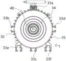
Example 1: referring to fig. 1, 2 and 3, a three-phase self-starting permanent magnet synchronous motor 1 includes a stator assembly 10 located at an outer periphery and a permanent magnet rotor assembly 20 located at an inner periphery, the stator assembly 10 is installed in an inner cavity of a motor housing 30, and a winding of the stator assembly 10 is electrically connected to a controller (not shown), the permanent magnet rotor assembly 20 includes a rotor core integrally installed with a rotating shaft 40;
preferably, in the present embodiment, the motor housing 30 includes a first end cover 31a and a housing cylinder 32 having an installation cavity, which are integrally connected (in other embodiments, a separate installation connection may also be adopted), and both ends of the rotating shaft 40 are respectively and relatively rotatably installed on the first end cover 31a and the second end cover 31 b; the shell cylinder 32 and the second end cover plate 31b are fixedly and hermetically installed into a whole; the related scheme of the controller on the mounting structure of the present embodiment can be specifically referred to the prior application 202011497354.3 of the present applicant, and the description of the present embodiment will not be repeated;
preferably, in the present embodiment, the outer periphery of the shell cylinder 32 is provided with a plurality of mounting sliding grooves distributed at intervals, wherein the bottom of the shell cylinder 32 is provided with at least 2 flush planar mounting sliding grooves for implementing planar mounting; particularly preferably, in the present embodiment, four rail mounting sliding grooves 33a, 33b, 33c, 33d distributed at intervals of 90 ° are provided at the periphery of the housing cylinder 32, and 2 flat mounting sliding grooves 33e, 33f in a flush state are further provided at the left and right sides of the rail mounting sliding groove 33c located at the bottom of the housing cylinder 32, so that the motor of the present embodiment can implement both 4-point mounting and planar mounting, and the mounting effect is flexible and reliable; when the plane installation is actually carried out, the rail installation sliding groove 33c positioned at the bottom can also be used as a plane installation sliding groove in a parallel and level state, so that the plane installation effect is further facilitated, and the structure is compact;
preferably, in the present embodiment, a flange 34 (in a convex shape) for being installed and connected with an external flange in a matching manner is provided on the first end cover plate 31 a; preferably, in order to facilitate the heat dissipation effect, the periphery of the shell cylinder 32 is further provided with a plurality of heat dissipation fins 35;
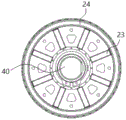
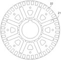
referring to fig. 4, 5 and 6, in the present embodiment, the rotor core is respectively provided with a plurality of permanent magnet embedding slots 21 circumferentially spaced apart from each other, and a plurality of squirrel cage slots 22 circumferentially spaced apart from each other, wherein the squirrel cage slots 22 are located at the periphery of the permanent magnet embedding slots 21, permanent magnets 23 are embedded in the permanent magnet embedding slots 21, and squirrel cage guide bars (not shown) are embedded in the squirrel cage slots 22; preferably, in the present embodiment, cast aluminum end rings 24 are respectively disposed on both sides of the permanent magnet rotor assembly 20, and the cage bars and the cast aluminum end rings 24 are integrally cast;
referring to fig. 7, in the present embodiment, preferably, the stator assembly 10 adopts a single-layer and double-layer hybrid winding 11, and the winding pitch can be automatically adjusted; referring further to fig. 8, the stator assembly 10 has 36 stator slots 12; the outer diameter range of the stator punching sheet 13 is 150-170mm, and the inner diameter range of the stator punching sheet 13 is 95-115 mm; the tooth width range of the stator punching of the stator assembly 10 is 3-5mm, and the height range of the yoke of the stator punching is 5-15 mm.
Preferably, in the present embodiment, the number of the magnetic poles of the permanent magnet rotor assembly 20 is 8, so as to ensure that the operating speed of the motor 1 is kept at 750RPM and is stable and constant no matter whether the motor works in any occasion; and the number of the cage grooves 22 is 4 times, 5 times or 6 times of the number of the magnetic poles, specifically, in the present embodiment, the number of the cage grooves 22 is 48 (i.e., 6 times of the number of the magnetic poles); the outer diameter of the rotor core is adapted to the inner diameter of the stator assembly 10, the outer diameter of the rotor core ranges from 95 mm to 115mm, and specifically, only a certain air gap is maintained between the rotor core and the stator assembly, which is not particularly limited in this embodiment.
The three-phase self-starting permanent magnet synchronous motor 1 provided by the embodiment comprises a permanent magnet rotor assembly 20 respectively provided with a permanent magnet 23 and a squirrel cage conducting bar, so that the three-phase self-starting permanent magnet synchronous motor 1 has the advantages of a three-phase asynchronous induction motor and a permanent magnet synchronous motor at the same time; in the synchronous driving working process, the squirrel cage conducting bars do not work any more, so that no rotor loss exists, the working efficiency of the motor is high, the step-out torque is large, the motor does not need to be started by a controller, and the motor provided by the embodiment is more reliable, more stable in use and lower in cost.
The working principle on which this embodiment is based is: the permanent magnet rotor component of the permanent magnet synchronous motor keeps necessary characteristics, the peripheral of the permanent magnet rotor component is provided with squirrel cage grooves 22 which are distributed at intervals, squirrel cage guide bars are formed after die casting, the motor is ensured to be started through a rotor (equivalent to the effect of the squirrel cage rotor) with the squirrel cage guide bar structure in the starting process, the starting function of an asynchronous motor is achieved, when the starting rotating speed of the motor reaches the vicinity of the synchronous rotating speed, because the permanent magnet rotor component 20 is provided with high-performance permanent magnet rare earth materials, the permanent magnet rotor component 20 rotates to generate electric potential, the electric potential is drawn into the working state of the permanent magnet rotor component 20 to enter the synchronous motor, the synchronous driving is finally achieved, the squirrel cage rotor does not work any more at the moment, the motor enters the state of the permanent magnet synchronous motor when working, and the high-efficiency and high-torque performance of the permanent magnet synchronous motor is achieved.
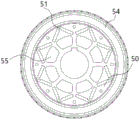
Example 2: in this embodiment 2, a permanent magnet rotor assembly is proposed, and the remaining technical solutions of the permanent magnet rotor assembly are the same as those in embodiment 1, except that, in order to make the motor have more excellent pull-in torque and step-out torque, reduce rotor resistance, and improve magnetic convergence effect, please refer to fig. 9, 10, and 11 in combination, the permanent magnet rotor assembly of this embodiment 2 includes a rotor core 50 integrally connected with a rotating shaft 30; the rotor core 50 is respectively provided with a plurality of permanent magnet embedded grooves 51 (specifically adopting an 8P magnetic pole scheme shown in the figure) distributed at intervals in the circumference and a plurality of squirrel cage grooves 52 (specifically adopting 48 magnetic poles shown in the figure) distributed at intervals in the circumference, wherein the squirrel cage grooves 52 are positioned at the periphery of the permanent magnet embedded grooves 51, permanent magnets (not shown in the figure) are embedded in the permanent magnet embedded grooves 51, squirrel cage guide bars 53 are embedded in the squirrel cage grooves 52, and the squirrel cage guide bars 53 and the cast aluminum end rings 54 are integrally cast; the permanent magnet embedding groove 51 comprises a left permanent magnet embedding groove unit 51a and a right permanent magnet embedding groove unit 51b which are connected into a V shape, wherein the connection point between the left permanent magnet embedding groove unit 51a and the right permanent magnet embedding groove unit 51b is close to one side of the squirrel cage groove 52; permanent magnets are embedded in the left permanent magnet embedding groove unit 51a and the right permanent magnet embedding groove unit 51 b; further preferably, in the present embodiment, the rotor core is provided with weight-reducing slots 55 distributed at intervals circumferentially, and the weight-reducing slots 55 are located on the inner periphery of the permanent magnet embedded slots 51 and are in one-to-one correspondence with the permanent magnet embedded slots 51, so that the material usage can be effectively reduced, and the improvement of the driving efficiency is facilitated;
particularly preferably, in the present embodiment, a V-shaped included angle between the left permanent magnet embedding groove unit 51a and the right permanent magnet embedding groove unit 51b is a 90 ° right angle; the squirrel cage groove 52 is arranged in a closed shape, and the bottom surface of the squirrel cage groove close to the rotor core is arranged in a plane shape; the distance between the squirrel cage groove 52 and the permanent magnet embedding groove 51 ranges from 1 mm to 3 mm; the width range of the rotor magnetic isolation bridge is 1-3 mm.
Compared with the structure of the permanent magnet rotor assembly in the embodiment 1, the present embodiment 2 further particularly proposes that the left permanent magnet embedded groove unit 51a and the right permanent magnet embedded groove unit 51b connected in a V shape are used as the permanent magnet embedded groove 51 structure of the permanent magnet rotor assembly, which can effectively improve the salient pole magnetic convergence effect of the motor, can also enable the motor to have more excellent pull-in torque and step-out torque, reduce the rotor resistance, and finally enable the motor to obtain better self-starting permanent magnet synchronous driving performance.
It will be evident to those skilled in the art that the utility model is not limited to the details of the foregoing illustrative embodiments, and that the present invention may be embodied in other specific forms without departing from the spirit or essential attributes thereof. The present embodiments are therefore to be considered in all respects as illustrative and not restrictive, the scope of the utility model being indicated by the appended claims rather than by the foregoing description, and all changes which come within the meaning and range of equivalency of the claims are therefore intended to be embraced therein. Any reference sign in a claim should not be construed as limiting the claim concerned.
Furthermore, it should be understood that although the present description refers to embodiments, not every embodiment may contain only a single embodiment, and such description is for clarity only, and those skilled in the art should integrate the description, and the embodiments may be combined as appropriate to form other embodiments understood by those skilled in the art.
Claims (10)
1. A permanent magnet rotor component is characterized by comprising a rotor iron core which is integrally installed and connected with a rotating shaft; the rotor core is provided with a plurality of permanent magnet embedded grooves distributed at intervals circumferentially and a plurality of squirrel cage grooves distributed at intervals circumferentially, wherein the squirrel cage grooves are positioned on the periphery of the permanent magnet embedded grooves, permanent magnets are embedded in the permanent magnet embedded grooves, and squirrel cage guide bars are embedded in the squirrel cage grooves; the permanent magnet embedded groove comprises a left permanent magnet embedded groove unit and a right permanent magnet embedded groove unit which are connected into a V shape.
2. The permanent magnet rotor assembly of claim 1 wherein the cage slots are arranged in a closed configuration and the slot bottom surface thereof adjacent the rotor core is arranged in a planar configuration.
3. The permanent magnet rotor assembly of claim 1 wherein the spacing between the squirrel cage slots and the permanent magnet inlay slots ranges from 1 to 3 mm; and/or the width range of the rotor magnetic isolation bridge is 1-3 mm.
4. The permanent magnet rotor assembly of claim 1 wherein the connection point between the left and right permanent magnet nesting units is near one side of the squirrel cage slot; and permanent magnets are embedded in the left permanent magnet embedding groove unit and the right permanent magnet embedding groove unit.
5. The permanent magnet rotor assembly according to claim 1 or 4, wherein the rotor core is provided with a plurality of weight-reducing grooves circumferentially distributed at intervals, and the weight-reducing grooves are positioned on the inner periphery of the permanent magnet embedded grooves and are matched with the permanent magnet embedded grooves in a one-to-one correspondence manner.
6. The permanent magnet rotor assembly according to claim 4, wherein the V-shaped included angle between the left permanent magnet slot-inserted unit and the right permanent magnet slot-inserted unit is a 90-degree right angle.
7. The permanent magnet rotor assembly of claim 1 wherein the outer diameter of the rotor core is in the range of 95-115 mm.
8. The permanent magnet rotor assembly of claim 1 wherein the number of poles of the permanent magnet rotor assembly is 8 poles and the number of cage grooves is 4 or 5 or 6 times the number of poles of the permanent magnet rotor assembly.
9. The permanent magnet rotor assembly of claim 1 wherein cast aluminum end rings are provided on each side of the permanent magnet rotor assembly.
10. The permanent magnet rotor assembly of claim 9 wherein the cage bars are cast integrally with the cast aluminum end rings.
Priority Applications (1)
| Application Number | Priority Date | Filing Date | Title |
|---|---|---|---|
| CN202122066418.0U CN215817689U (en) | 2021-08-30 | 2021-08-30 | Permanent magnet rotor assembly |
Applications Claiming Priority (1)
| Application Number | Priority Date | Filing Date | Title |
|---|---|---|---|
| CN202122066418.0U CN215817689U (en) | 2021-08-30 | 2021-08-30 | Permanent magnet rotor assembly |
Publications (1)
| Publication Number | Publication Date |
|---|---|
| CN215817689U true CN215817689U (en) | 2022-02-11 |
Family
ID=80153479
Family Applications (1)
| Application Number | Title | Priority Date | Filing Date |
|---|---|---|---|
| CN202122066418.0U Active CN215817689U (en) | 2021-08-30 | 2021-08-30 | Permanent magnet rotor assembly |
Country Status (1)
| Country | Link |
|---|---|
| CN (1) | CN215817689U (en) |
-
2021
- 2021-08-30 CN CN202122066418.0U patent/CN215817689U/en active Active
Similar Documents
| Publication | Publication Date | Title |
|---|---|---|
| CN111064332A (en) | Bilateral Halbach alternate pole type permanent magnet vernier motor | |
| CN102315707A (en) | Mixed-excitation high-efficiency motor based on Halbach array | |
| CN104160600A (en) | Electromagnetic generator | |
| CN105743309A (en) | Permanent magnet excitation electric generator | |
| CN204517610U (en) | A kind of Hybrid Excitation Switched Reluctance Motor and stator structure thereof | |
| CN112865465B (en) | Magnetic flux switching permanent magnet motor structure for inhibiting torque pulsation | |
| CN111082622A (en) | Decoupling type birotor alternating pole permanent magnet motor | |
| CN111245187B (en) | Annular winding dual-rotor flux reversal motor | |
| CN104753213A (en) | Permanent-magnet DC brushless motor | |
| CN215817689U (en) | Permanent magnet rotor assembly | |
| CN109256879A (en) | A kind of Double-stator motor of ectonexine permanent magnet dislocation | |
| CN104753280A (en) | Hybrid excitation switched reluctance motor and stator structure thereof | |
| CN215817867U (en) | Three-phase self-starting permanent magnet synchronous motor | |
| CN110112844A (en) | A kind of doubly salient permanent magnet motor | |
| CN102315737A (en) | Mixed-excitation high-efficiency motor | |
| CN213602467U (en) | Novel permanent magnet motor structure | |
| CN110808673B (en) | Novel double-stator Halbach alternating pole permanent magnet vernier motor | |
| CN103618391B (en) | A kind of permanent magnet brushless electromotor of ten pole 12 grooves | |
| CN209375272U (en) | A kind of Double-stator motor of ectonexine permanent magnet dislocation | |
| CN208369409U (en) | A kind of permanent magnet direct driving motor with cooling structure | |
| CN111654122A (en) | High-efficiency low-noise motor for ceiling fan and ceiling fan | |
| CN201699490U (en) | Reluctance motor | |
| CN111162613A (en) | Multiphase skewed slot shift extremely-low vibration noise permanent magnet motor | |
| CN110601474A (en) | Radial magnetic field composite flux switching motor | |
| CN203660681U (en) | Ten-pole and twelve-groove permanent magnetic brushless motor |
Legal Events
| Date | Code | Title | Description |
|---|---|---|---|
| GR01 | Patent grant | ||
| GR01 | Patent grant |