CN215755145U - Production line of leak hunting device and inner bag - Google Patents
Production line of leak hunting device and inner bag Download PDFInfo
- Publication number
- CN215755145U CN215755145U CN202123388003.1U CN202123388003U CN215755145U CN 215755145 U CN215755145 U CN 215755145U CN 202123388003 U CN202123388003 U CN 202123388003U CN 215755145 U CN215755145 U CN 215755145U
- Authority
- CN
- China
- Prior art keywords
- driving
- clamping
- inner container
- driving mechanism
- sealing
- Prior art date
- Legal status (The legal status is an assumption and is not a legal conclusion. Google has not performed a legal analysis and makes no representation as to the accuracy of the status listed.)
- Active
Links
Images


Landscapes
- Examining Or Testing Airtightness (AREA)
Abstract
The application provides a production line of leak hunting device and inner bag, and the leak hunting device includes: the automatic positioning tool comprises a lifting clamping device and a jacking device, wherein the lifting clamping device comprises a clamping mechanism and a first driving mechanism capable of driving the clamping mechanism to move up and down; the detection head device comprises an automatic positioning mechanism capable of positioning the pipe joint of the inner container, an automatic sealing mechanism capable of sealing the pipe joint and a first gas channel capable of being used for conveying tracer gas to the position to be detected on the outer surface of the inner container. The leak detection device that this scheme provided utilizes automatic structure to replace manual work, more uses manpower sparingly, has also improved the line automation degree of producing, helps promoting the production efficiency and the leak detection precision of inner bag.
Description
Technical Field
The application relates to the technical field of tightness testing of inner containers, in particular to a leak detection device and a production line of the inner containers.
Background
In the related art, a leak tightness test procedure of positions of pipe joints (such as pipe joints of a water inlet pipe joint and a water outlet pipe joint of a water heater inner container) and inner container welding seams of an inner container (such as an inner container of a water heater) related in a processing production process of the inner container is mainly completed in a manual operation mode, for example: an operator connects the air pipe tool with the water inlet pipe joint and the water outlet pipe joint of the inner container, starts to inflate the inner container to keep a certain pressure in the inner container, then paints foam around the water inlet/outlet pipe joint by a brush, maintains the pressure for a specific time according to different types of products, visually checks whether bubbles generated by air leakage exist at the position where the foam is painted, and if the bubbles do not exist, the sealing is good and the product is qualified. The manual operation mode has the problems of low efficiency and low precision.
SUMMERY OF THE UTILITY MODEL
An aim at of this application provides a leak hunting device, and this leak hunting device can be used for the leak hunting of inner bag to realize the automation of inner bag leak hunting, help promoting the production efficiency and the leak hunting precision of inner bag.
In order to solve the technical problem, the following technical scheme is adopted in the application:
the technical scheme in one aspect of this application provides a leak hunting device, can be used for the leak hunting of inner bag, includes: the automatic positioning tool comprises a lifting clamping device and a jacking device, the lifting clamping device comprises a clamping mechanism and a first driving mechanism capable of driving the clamping mechanism to perform lifting motion, the clamping mechanism is configured to clamp the liner, the clamping mechanism comprises at least two clamping claw parts and a second driving mechanism, the clamping claw parts are arranged at intervals, each clamping claw part is provided with a floating part, each floating part can perform lifting motion relative to the corresponding clamping claw part, the second driving mechanism is connected with the corresponding clamping claw part, and the second driving mechanism is configured to drive at least one clamping claw part to move so as to enable the clamping claw parts to approach or depart from each other, the jacking device is configured to support the inner container and drive the inner container to do lifting movement; the detection head device comprises an automatic positioning mechanism, an automatic sealing mechanism and a first gas channel, wherein the automatic positioning mechanism is configured to be capable of positioning a pipe joint of the inner container, the automatic sealing mechanism is configured to be capable of sealing the pipe joint, and the first gas channel is arranged to be capable of being used for conveying tracer gas to a position to be detected on the outer surface of the inner container.
According to some aspects of the present disclosure, the first drive mechanism comprises: a first driving member; the first rotating piece can rotate under the driving of the first driving piece; the clamping mechanism is connected with the first moving piece and can perform lifting motion under the driving of the first moving piece; the first guide rail is connected with the first moving part and can guide the movement of the first moving part; the two sides of the first guide rail are respectively provided with a limiting piece, and the limiting pieces can be used for abutting against the first moving piece to limit the movement stroke of the first moving piece.
According to some technical solutions of the present application, the floating member is provided with one or more rollers, and the rollers are rotatably connected with the floating member; the clamping jaw part comprises one or more guide shafts, the floating part can move along the axial direction of the guide shafts, and a first linear bearing is arranged between the floating part and the guide shafts; the second driving mechanism comprises a second driving piece, a second rotating piece and a second guide rail, the clamping claw parts are arranged on the second guide rail and can slide along the second guide rail, each clamping claw part is respectively provided with a second moving piece, the second rotating piece is in tooth transmission or spiral transmission fit with the second moving pieces of at least two clamping claw parts, and the second rotating piece is connected with the second driving piece and can rotate under the driving of the second driving piece; the lifting clamping and holding device is limited by a first base and a second base, the first driving mechanism is arranged on the first base, the second base is connected with the first driving mechanism and can be driven by the first driving mechanism, and the clamping and holding mechanism is arranged on the second base.
According to some aspects of the present disclosure, the jacking device includes: the first supporting block is used for supporting the inner container; the third driving piece is configured to drive the first supporting block to do lifting motion; and the bearing seat is connected with the first supporting block and the third driving piece, so that the first supporting block and the third driving piece can rotate relatively.
According to some technical solutions of the present application, the jacking device further includes: a transmission belt connecting seat; the supporting rod is connected with the conveying belt connecting seat; the third base is connected with the supporting rod, a second linear bearing is arranged on the third base, a guide rod penetrates through the second linear bearing, and the guide rod is connected with the bearing seat; the third driving member is mounted on the third base.
According to some aspects of the present disclosure, the automatic positioning mechanism includes a clamp assembly, a third drive mechanism configured to drive the clamp assembly to move to configure the position of the clamp assembly, and a fourth drive mechanism configured to drive the clamp assembly to clamp or expand; the automatic sealing mechanism comprises a sealing head and a fifth driving mechanism, wherein the fifth driving mechanism is configured to drive the sealing head to move, and the sealing head can seal or open the pipe joint through movement.
According to some technical solutions of the present application, the clamp assembly includes a first positioning block and a second positioning block, the first positioning block and the second positioning block are oppositely disposed, and an accommodating portion for accommodating the pipe joint is formed between the first positioning block and the second positioning block, wherein one of the first positioning block and the second positioning block is fixedly disposed, and the other is a pneumatic finger integrally disposed with the fourth driving mechanism, and the pneumatic finger is movable to increase or decrease a distance between the first positioning block and the second positioning block; a second gas channel penetrates through the sealing head, and when the sealing head seals the pipe joint, the second gas channel is communicated with the space in the inner container; the automatic sealing mechanism is limited by a detection head part, the sealing heads are arranged on the detection head part, the number of the sealing heads on the detection head part is 2, the sealing heads are used for correspondingly sealing a water inlet pipe joint and a water outlet pipe joint on the inner container, and the fifth driving mechanism is connected with the detection head part and drives the detection head part to move.
According to some aspects of the present disclosure, the detection head assembly defines a head module, the automatic positioning mechanism, the automatic sealing mechanism, and the first gas channel being part of the head module; the detection head device also comprises a sixth driving mechanism and a sensor; the sensor is arranged on the head module and is configured to detect the position information of the head module; the sixth driving mechanism is electrically connected with the sensor, is configured to drive the head module to move, and can configure the position of the head module according to the position information from the sensor.
According to some aspects of the present disclosure, the leak detection apparatus further includes: the frame comprises a top frame and side frames, and an in-frame space is enclosed by the top frame and the side frames; the lifting clamp is connected with the top frame, the jacking device is accommodated in the space in the frame, the jacking device is located below the lifting clamp, and the detection head device is connected with the side frame.
The technical scheme of this application on the other hand provides a production line of inner bag, includes: a conveyor belt, which is configured to convey the liner; in the leak detection device according to any one of the above technical solutions, an automatic positioning tool of the leak detection device is configured to pick up the inner container to be leak-detected from the conveyor belt.
According to some technical schemes of this application, the production line of inner bag still includes: the positioning seat is positioned on the conveying belt and can move along with the conveying belt; the positioning seat comprises second supporting blocks which are distributed circumferentially around an avoidance area, and the second supporting blocks can be used for supporting the liner; the avoiding area can be used for a jacking device of the leak detection device to penetrate through.
In this application, leak hunting device includes automatic positioning frock and detects first device, it contains automatic positioning mechanism to detect first device, automatic sealing mechanism and first gas passage, like this, utilize automatic positioning frock drive inner bag to predetermineeing the position and with the inner bag location in this predetermined position, utilize automatic positioning mechanism to fix a position the coupling of the inner bag of predetermined position department, utilize automatic sealing mechanism to seal the coupling of being positioned and make the inner bag can be by evacuation processing, and utilize first gas passage with tracer gas (tracer gas such as helium, ammonia etc.) direction inner bag surface wait to detect position department (wait to detect the position for the inner bag surface is located the position around the coupling, certainly also can be the inner bag welding seam etc. on inner bag surface). Therefore, the leakage detection of the inner container can be realized by taking the content of the tracer gas in the inner container cavity as the judgment basis of the tightness of the position to be detected of the inner container. And this structure utilizes automatic structure to replace manual work, more uses manpower sparingly, has also improved the line automation degree of producing, helps promoting the production efficiency and the leak hunting precision of inner bag.
It is to be understood that both the foregoing general description and the following detailed description are exemplary and explanatory only and are not restrictive of the application.
Drawings
The above and other objects, features and advantages of the present application will become more apparent by describing in detail exemplary embodiments thereof with reference to the attached drawings.
Fig. 1 is a schematic structural view of a liner production line according to an embodiment of the present invention.
Fig. 2 is a schematic structural diagram of a lifting clamp device according to an embodiment of the present application.
Fig. 3 is a schematic structural diagram of an assembly of a jacking device and a conveyor belt according to an embodiment of the present application.
Fig. 4 is a schematic structural view of a detection head device according to an embodiment of the present application.
Fig. 5 is a schematic structural view of a frame according to an embodiment of the present application.
Fig. 6 is an enlarged structural schematic view of the C portion shown in fig. 1.
Fig. 7 is an enlarged structural schematic view of the D portion shown in fig. 4.
The reference numerals are explained below:
automatically positioning a tool A; a lifting clamping device 100; a first drive mechanism 110; a first motor 111; a first rack 113; a first guide rail 114; a stopper 115; a clamping mechanism 120; a claw portion 121; a guide shaft 1211; a first linear bearing 1212; floating members 1213; a roller 1214; a second drive mechanism 122; a second motor 1221; a second gear 1222; a second rack 1223; a second rail 1224; a first base 131; a second base 132; a detection element 140; a jacking device 200; a first carrier block 201; a third drive member 202; a bearing seat 203; a transmission belt connecting seat 204; a support rod 205; a third base 206; a second linear bearing 207; a guide rod 208; a detection head device 300; a head module B; an automatic positioning mechanism 310; a clamp assembly 311; a first positioning block 3111; a second positioning block 3112; a third drive mechanism 312; first electric cylinder 3121; a third guide rail 3122; an automatic sealing mechanism 320; the detection head member 321; a fifth drive mechanism 322; a second electric cylinder 3221; a third linear bearing 3222; a guide rod 3223; a sealing head 323; a second gas passage 324; a first gas channel 330; a sensor 340; a sixth drive mechanism 350; a fixing plate 360; a frame 400; a top frame 410; a first connection plate 411; a side frame 420; a support 421; a second link plate 4211; a pull rod 422; an adjustment plate 423; an inner container 20; a pipe joint 21; a conveying belt 30; a positioning seat 40; a second carrier block 41; avoiding the zone 42.
Detailed Description
While this application is susceptible of embodiment in different forms, there is shown in the drawings and will herein be described in detail only some specific embodiments thereof with the understanding that the present disclosure is to be considered as an exemplification of the principles of the application and is not intended to limit the application to that as illustrated herein.
Thus, a feature indicated in this specification is intended to describe one of the features of an embodiment of the application and does not imply that every embodiment of the application must have the described feature. Further, it should be noted that this specification describes many features. Although some features may be combined to show a possible system design, these features may also be used in other combinations not explicitly described. Thus, the combinations illustrated are not intended to be limiting unless otherwise specified.
In the embodiments shown in the drawings, directional references (such as upper, lower, inner, outer, left, right, front, rear, S, J, etc.) are used to explain the structure and motion of various elements of the present application not absolutely, but relatively. These descriptions are appropriate when the elements are in the positions shown in the drawings. If the description of the positions of these elements changes, the indication of these directions changes accordingly.
Example embodiments will now be described more fully with reference to the accompanying drawings. Example embodiments may, however, be embodied in many different forms and should not be construed as limited to the examples set forth herein; rather, these example embodiments are provided so that this disclosure will be thorough and complete, and will fully convey the concept of example embodiments to those skilled in the art. The drawings are merely schematic illustrations of the present application and are not necessarily drawn to scale. The same reference numerals in the drawings denote the same or similar parts, and thus their repetitive description will be omitted.
The preferred embodiments of the present application will be further described in detail below with reference to the accompanying drawings of the present specification.
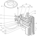
As shown in fig. 1, embodiments of one aspect of the present application provide a leak detection apparatus that can be used to detect leaks in a liner 20, such as the liner 20 of a water heater. The leak detection device includes an automatic positioning tool a and a detection head device 300.
Specifically, the automatic positioning tool a is configured to drive the inner container 20 to move so as to configure the position of the inner container 20, wherein the movement of the inner container 20 driven by the automatic positioning tool a includes a preset position, and the automatic positioning tool a is further configured to position the inner container 20 at the configured preset position.
The test head device 300 includes an automatic positioning mechanism 310 and an automatic sealing mechanism 320, wherein the automatic positioning mechanism 310 is configured to position the pipe joint 21 of the inner container 20, and the automatic sealing mechanism 320 is configured to seal the pipe joint 21. Thus, the one-stop positioning of the pipe joint 21 and the sealing of the pipe joint 21 are realized by using the detection head device 300, and the sealing effect and the sealing precision are better.
The test head assembly 300 further includes a first gas passageway 330, the first gas passageway 330 being configured to deliver a trace gas to the exterior surface of the inner bladder 20 at a location to be tested. Like this, detect first device 300 one-stop to the position of waiting to detect of the surface of inner bag 20 after being positioned and carry tracer gas, tracer gas's transport position precision is higher, has ensured the precision that treats the position leakproofness of detecting better.
In general, for the leak detection device, the automatic positioning tool a can be used to drive the liner 20 to move to a preset position, and position the liner 20 at the preset position, the automatic positioning mechanism 310 can be used to position the pipe joint 21 of the liner 20 at the preset position, the automatic sealing mechanism 320 can be used to seal the positioned pipe joint 21 so that the inner cavity of the liner 20 can be evacuated, and the first gas channel 330 can be used to guide a tracer gas (the tracer gas, for example, contains helium gas and/or ammonia gas, etc.) to a position to be detected on the outer surface of the liner 20 (the position to be detected, for example, the position on the surface of the liner 20 around the pipe joint 21, and of course, a liner weld seam on the outer surface of the liner 20, etc.). Like this, can regard as the judgement foundation of the position leakproofness that detects of inner bag 20 based on the tracer gas content in the inner bag 20 cavity, for example, if detect tracer gas in the gas of taking out in the inner bag 20 cavity or the tracer gas content that detects is higher than predetermineeing the threshold value, then judge that there is sealed defect in the position that detects, if not detect tracer gas in the gas of taking out in the inner bag 20 cavity or the tracer gas content that detects is less than or equal to predetermineeing the threshold value, then judge that there is not sealed defect in the position that detects. This structure utilizes automatic structure to replace manual work, realizes that inner bag 20 waits to detect the leakproofness of position and detects, more uses manpower sparingly, has also improved production line automation degree, helps promoting inner bag 20's production efficiency and leak hunting precision.
In some embodiments of the present application, as shown in fig. 1, the automatic positioning tool a includes a lifting clamp device 100 and a jacking device 200. Specifically, the lifting clamping device 100 includes a clamping mechanism 120 and a first driving mechanism 110 capable of driving the clamping mechanism 120 to perform a lifting motion, and the clamping mechanism 120 is configured to clamp the inner container 20. The jacking device 200 is configured to support the inner container 20 and drive the inner container 20 to move up and down.
Thus, after the liner 20 reaches the set leak detection station, the clamping mechanism 120 reaches the designated position under the driving of the first driving mechanism 110 to clamp the liner 20, and the jacking device 200 drives the liner 20 clamped by the clamping mechanism 120 to move up and down. In this way, the position of the inner container 20 can be configured, for example, to drive the inner container 20 to move to a preset position (i.e., a certain preset height position along the lifting direction S) along the lifting direction S. And the inner container 20 is supported by the clamping mechanism 120, so that the risk of toppling over the inner container 20 can be reduced, and the motion safety of the inner container 20 driven by the jacking device 200 can be better guaranteed.
In some embodiments of the present application, as shown in fig. 2, the first driving mechanism 110 includes a first motor 111 (i.e., a first driving member), a first gear (i.e., a first rotating member, the first gear is not shown), a first rack 113 (i.e., a first moving member), and the like. The first gear is connected with the first motor 111 and can rotate under the driving of the first motor 111, the first rack 113 is meshed with the first gear, and the first rack 113 is connected with the clamping mechanism 120. Thus, the first rack 113 can perform a displacement motion along the lifting direction S under the driving of the first gear, so that the clamping mechanism 120 can perform a lifting motion along with the first rack 113. The structure is simple, the cost is low, the motion precision is high, and the position precision of the clamping mechanism 120 and the product cost can be considered.
As shown in fig. 2, the first driving mechanism 110 further includes a first guide rail 114, and the first guide rail 114 is connected to the first rack 113 and can guide the movement of the first rack 113. Like this, the skew is difficult to take place for the in-process of first rack 113 motion, can make the position precision of pressing from both sides embracing mechanism 120 higher on the one hand, can promote the cooperation nature between pressing from both sides embracing mechanism 120 and jacking device 200 like this, avoid inner bag 20 to receive jacking device 200 and press from both sides embracing mechanism 120 extrusion to its driven in-process at jacking device 200, reduce inner bag 20 and damage the risk, on the other hand, can make the moment conduction between first rack 113 and the first gear more even, first rack 113 and the difficult damage of first gear, the life-span of product has been ensured better.
Further, as shown in fig. 2, the first driving mechanism 110 further includes a limiting member 115. The two sides of the first rail 114 are respectively provided with a limiting member 115, and the limiting members 115 can be used to abut against the first rack 113 to limit the movement stroke of the first rack 113. This can restrict the first rack 113 from being disengaged from the first rail 114, thereby better ensuring stability and reliability of the support of the clasping mechanism 120.
Of course, it is understood that the present disclosure is not limited thereto, and in other embodiments, a screw transmission structure including a lead screw and a nut may be adopted to replace the first gear and the first rack 113, so as to achieve the purpose of driving the clamping mechanism 120 to move. Alternatively, the first driving member, the first gear and the first rack 113 may be replaced by a structure of an electric cylinder matching with the guide rail, so as to achieve the purpose of driving the clamping mechanism 120 to move.
In some embodiments of the present application, as shown in fig. 2, the lifting clamp device 100 further includes a first base 131, the first driving mechanism 110 is disposed on the first base 131 and located on one side of the first base 131, the clamping mechanism 120 is located on the other side of the first base 131, and the first rack 113 of the first driving mechanism 110 penetrates through the first base 131 and extends to the other side of the first base 131 to be connected to the clamping mechanism 120.
Further, as shown in fig. 2, a through hole is formed in the first base 131, and the first rack 113 passes through the first base 131 along the through hole. Positions on both sides of the through-hole on the first base 131 are respectively formed as connection positions for connection assembly of the first base 131. Specifically, for example, the first connection plate 411 of the frame 400 is connected to the connection position, so that the first base 131 is more stable.
In some embodiments of the present application, as shown in fig. 2, the clasping mechanism 120 includes at least two jaw portions 121 and a second driving mechanism 122. The claw portions 121 are arranged at intervals. The second driving mechanism 122 is connected to the jaw portions 121 and configured to drive at least one of the jaw portions 121 to move so as to move the jaw portions 121 closer to or away from each other. In this way, the second driving mechanism 122 drives the clamping claw parts 121 to move closer to or away from each other, and the clamping and holding mechanism 120 can be correspondingly controlled to correspondingly hold the liner 20 or release the liner 20.
As shown in fig. 2, each of the claw portions 121 is provided with a floating member 1213, and the floating member 1213 is movable up and down relative to the claw portion 121. In this way, the inner container 20 is embraced by the clamping and embracing mechanism 120 by using the floating member 1213 of the clamping claw part 121, so that the inner container 20 embraced by the floating member 1213 has a certain degree of freedom of movement in the lifting direction S, and thus, in the process that the inner container 20 embraced by the floating member 1213 is driven by the jacking device 200 to perform lifting movement, the inner container 20 can be prevented from being extruded by the jacking device 200 and the clamping and embracing mechanism 120 through the movement of the floating member 1213, the risk of deformation of the inner container 20 is reduced, and in the structure, the floating member 1213 moves along with the inner container 20, so that the surface friction between the inner container 20 and the inner container is avoided, and the risk of scraping damage to the surface of the inner container 20 can be reduced.
Further alternatively, as shown in fig. 2, one or more rollers 1214 are provided on the floating member 1213, and the rollers 1214 are rotatably connected to the floating member 1213. In this way, the clamping mechanism 120 can further utilize the roller 1214 on the floating members 1213 to clamp the inner container 20, and when the inner container 20 rotates between the floating members 1213, the roller 1214 is in rolling contact with the surface of the inner container 20, so that the surface of the inner container 20 is prevented from being directly rubbed, and the risk of scraping and damaging the surface of the inner container 20 can be further reduced.
For example, as shown in fig. 2, the clasping mechanism 120 includes two clamping jaws 121, and the two clamping jaws 121 are disposed opposite to each other with a gap therebetween. Each of the claw portions 121 includes two guide shafts 1211, and the two guide shafts 1211 are spaced apart from each other and are substantially parallel to each other. A first linear bearing 1212 is sleeved outside each guide shaft 1211, and the guide shafts 1211 and the first linear bearing 1212 can slide relatively. The floating members 1213 are connected to first linear bearings 1212 on two guide shafts 1211, respectively, so that the floating members 1213 can slide along the guide shafts 1211. With the structure, the floating members 1213 are connected stably, and meanwhile, the sliding smoothness of the floating members 1213 is good, so that the inner container 20 is not easily squeezed between the clamping mechanism 120 and the jacking device 200, and the floating members 1213 are connected with the two guide shafts 1211, so that the floating members 1213 do not rotate around the guide shafts 1211 while the sliding connection is realized, and the clamping effect on the inner container 20 can be better ensured.
The floating member 1213 is provided with two rollers 1214 (of course, the number of the rollers 1214 may be adjusted to 1 or 3 or more than 3 according to specific requirements), and the two rollers 1214 are respectively connected with the floating member 1213 through shafts, so that the rollers 1214 can rotate relative to the floating member 1213. The two rollers 1214 are spaced apart from each other so that each jaw 121 provides two support positions for supporting the surface of the liner 20. Thus, four supporting positions are formed between the two oppositely arranged clamping claw parts 121 along the circumferential direction of the inner container 20, the inner container 20 can be supported more uniformly in the circumferential direction, and the inner container 20 can be prevented from toppling over better.
Of course, the present solution is not limited to this, and in other embodiments, the number of the clamping claw portions 121 may be 3, 4 or more according to specific requirements.
In certain embodiments, as shown in fig. 2, the second drive mechanism 122 includes a second motor 1221 (i.e., a second drive member), a second gear 1222 (i.e., a second rotational member), and a second guide rail 1224.
The second gear 1222 is connected to the second motor 1221 and is rotatable by the second motor 1221.
The claw portion 121 is provided on the second rail 1224 and is slidable along the second rail 1224. Each of the clamping claw portions 121 is provided with a second rack 1223 (i.e., a second moving member), and the second gear 1222 is in tooth-meshing transmission with the second racks 1223 of the at least two clamping claw portions 121. Thus, the at least two clamping claw parts 121 slide along the respective second guide rails 1224 under the driving of the second motor 1221 to hold the liner 20 or release the liner 20, so that the number of driving parts is saved, the movement synchronism among the clamping claw parts 121 is good, the acting force on the liner 20 in the process of holding the liner 20 is more uniform, and the damage to the liner 20 can be reduced.
For example, as shown in fig. 2, the lifting clamp device 100 includes a second base 132, and the second base 132 is located on a side of the first base 131 opposite to the first driving mechanism 110 and connected to the first rack 113 of the first driving mechanism 110. The clamping mechanism 120 is disposed on the second base 132.
More specifically, a second motor 1221 is mounted on a surface of the second base 132 disposed facing the first base 131, a second gear 1222 is located on a side of the second base 132 facing away from the first base 131, and an output shaft of the second motor 1221 passes through the second base 132 to be connected to the second gear 1222. The second gear 1222 is provided with a second rack 1223 at opposite sides thereof, and the second rack 1223 at both sides of the second gear 1222 is engaged with the second gear 1222. A second guide rail 1224 is disposed between each second rack 1223 and the second base 132, and the second guide rail 1224 is used to guide the movement of the second rack 1223. Each of the second racks 1223 has a claw portion 121 attached thereto, and thus the second motor 1221 drives the second gear 1222 to rotate so that the two claw portions 121 can move closer to or away from each other.
Further optionally, as shown in fig. 2, the lifting clamp device 100 further includes a detection element 140, for example, the detection element 140 is further disposed on a side of the second base 132 facing away from the first base 131. The detecting element 140 (e.g., a distance sensor, etc.) may be configured to detect a distance from the inner container 20, so that the first driving mechanism 110 may control the holding mechanism 120 to ascend or descend based on the distance between the detecting element 140 and the inner container 20, thereby further ensuring that the roller 1214 of the holding mechanism 120 holds the inner container 20.
In certain embodiments, as shown in fig. 3, the jacking device 200 includes a first pallet 201, a bearing block 203, and a third drive 202. Specifically, the first supporting block 201 is used for supporting the liner 20; the third driving member 202 is configured to drive the first supporting block 201 to move up and down; the bearing seat 203 is connected with the first supporting block 201 and the third driving member 202, so that the first supporting block 201 and the third driving member 202 can rotate relatively.
The liner 20 is supported by the first support block 201, so that the liner 20 has a larger stress area, and the risk of stress deformation of the liner 20 is reduced.
The bearing seat 203 is arranged between the first supporting block 201 and the third driving element 202, so that the inner container 20 can rotate relative to the third driving element 202 based on the bearing seat 203 to perform circumferential position adjustment, and thus, the pipe joint 21 of the inner container 20 is positioned by the automatic positioning mechanism 310 more flexibly, and the relative acting force and damage between the inner container 20 and the automatic positioning mechanism 310 are reduced.
Optionally, the third driving element 202 includes an air cylinder, and the air cylinder can flexibly set the supporting height of the inner container 20, and the inner container 20 is jacked to the preset height position, so that the inner container 20 of the same model can be driven to ascend and descend based on the same preset height position, and the ascending and descending height does not need to be monitored and adjusted separately for each driving, and thus, the control program of the leak detection device is simplified, the operation is more efficient, and the failure rate is lower.
In some embodiments, as shown in fig. 3, the jacking device 200 further comprises a conveyor belt attachment seat 204. The jacking device 200 can be connected with a transmission belt through the transmission belt connecting seat 204, so that the jacking device 200 can directly pick up the inner container 20 from the transmission belt, the transplanting process can be saved, and the production is more efficient.
Further optionally, as shown in fig. 3, the jacking device 200 further comprises a support rod 205 and a third base 206. The supporting rod 205 is connected with the transmission belt connecting seat 204; the third base 206 is connected with the support rod 205, a second linear bearing 207 is arranged on the third base 206, a guide rod 208 penetrates through the second linear bearing 207, and the guide rod 208 is connected with the bearing seat 203. In this way, the guide rod 208 and the second linear bearing 207 are matched to guide the lifting motion of the bearing seat 203, so that the acting force direction of the jacking device 200 on the liner 20 can be better ensured to be stable, the risk of toppling the liner 20 is reduced, and the risk of extrusion of the liner 20 by the jacking device 200 and the clamping mechanism 120 is also reduced.
Further alternatively, as shown in fig. 3, the third drive member 202 is mounted on a third base 206. Like this, realized that whole jacking device 200 is assembled to the transmission band 30 on the transmission band through transmission band connecting seat 204, can realize between jacking device 200 and the transmission band 30 position accuracy, guarantee the stability, the accuracy nature of picking up inner bag 20 better.
In certain embodiments, as shown in fig. 4, the automatic positioning mechanism 310 includes a clamp assembly 311, a third drive mechanism 312, and a fourth drive mechanism, the third drive mechanism 312 configured to drive the clamp assembly 311 to move to configure the position of the clamp assembly 311, and the fourth drive mechanism configured to drive the clamp assembly 311 to clamp or expand.
Thus, the gripper assembly 311 can be driven by the third driving mechanism 312 to the target position in the feeding direction J, and can grip the pipe joint 21 of the liner 20 to position the pipe joint 21 under the driving of the fourth driving mechanism at the target position, or can be opened to release the pipe joint 21 of the liner 20 under the driving of the fourth driving mechanism at the target position. Thus, the automatic positioning mechanism 310 can automatically position the pipe joint 21, and has the advantages of simple structure and low cost.
For example, as shown in fig. 4, the third driving mechanism 312 specifically includes a first electric cylinder 3121 and a third guide rail 3122, the clamp assembly 311 can move in the feeding direction J under the driving of the first electric cylinder 3121, and the movement of the clamp assembly 311 under the driving of the first electric cylinder 3121 is guided by the third guide rail 3122.
It is understood that the present disclosure is not limited thereto, and in other embodiments, the first electric cylinder 3121 may be replaced with a motor and a rack and pinion mechanism, or the first electric cylinder 3121 and the third guide rail 3122 may also be replaced with a motor and a lead screw nut mechanism.
Further alternatively, as shown in fig. 4, the clamp assembly 311 includes a first positioning block 3111 and a second positioning block 3112, the first positioning block 3111 is disposed opposite to the second positioning block 3112, and a receiving portion for receiving the pipe joint 21 is formed between the first positioning block 3111 and the second positioning block 3112. More specifically, the accommodating portion between the first positioning block 3111 and the second positioning block 3112 is configured to penetrate through both ends in the elevation direction S, so that the risk of collision between the first positioning block 3111 or the second positioning block 3112 and the pipe joint 21 can be reduced.
The first positioning block 3111 is disposed in a fixed position (it is understood that the fixed position is relative to the movement between the first positioning block 3111 and the second positioning block 3112, that is, the clamping or unclamping operation of the clamp assembly 311 is performed in a form of the first positioning block 3111 being stationary and the second positioning block 3112 moving, and does not mean that the position of the first positioning block 3111 is absolutely fixed, in practice, the first positioning block 3111 may be designed to move along the feeding direction J under the driving of the third driving mechanism 312, and it is understood that the position of the first positioning block 3111 may not change along with the driving of the third driving mechanism 312 according to specific requirements). The second positioning block 3112 is a pneumatic finger integrally provided with the fourth driving mechanism, and the pneumatic finger is movable to increase or decrease a distance between the first positioning block 3111 and the second positioning block 3112. The structure is more compact, the space volume of the product can be saved, the weight reduction of the driving object of the third driving mechanism 312 is facilitated, the driving loss is reduced, and the driving precision and the efficiency are improved.
Of course, the present embodiment is not limited to this, and in other embodiments, the first positioning block 3111 and the second positioning block 3112 may be configured to be movable relative to each other under the driving of the driving member so that the first positioning block 3111 and the second positioning block 3112 are relatively close to each other or relatively far from each other, with reference to the structure in which the second driving mechanism 122 drives the claw portion 121.
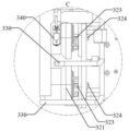
In some embodiments, as will be understood in conjunction with fig. 4 and 6, the automatic sealing mechanism 320 includes a sealing head 323 (specifically, for example, a plug) and a fifth driving mechanism 322, and the fifth driving mechanism 322 is configured to drive the sealing head 323 to move, and the sealing head 323 can be moved to seal or open the pipe joint 21. Thus, the automatic sealing mechanism 320 realizes the automatic sealing of the pipe joint 21, and has the advantages of simple structure and low cost.
For example, as shown in fig. 4, the fifth driving mechanism 322 specifically includes a second electric cylinder 3221, a third linear bearing 3222, and a guide rod 3223. A second electric cylinder 3221 is connected to the sealing head 323 and can drive the sealing head 323 in movement. The guide rod 3223 is connected to the sealing head 323, and the guide rod 3223 is inserted into the third linear bearing 3222 and can move along the third linear bearing 3222 to guide the movement of the sealing head 323 driven by the second electric cylinder 3221. Therefore, the accuracy of the movement of the sealing head 323 along the feeding direction J can be improved, the sealing reliability of the sealing head 323 to the pipe joint 21 is better guaranteed, and the leak detection error caused by the untight sealing of the pipe joint 21 can be reduced.
It is understood that the present invention is not limited thereto, and in other embodiments, a motor and a rack and pinion mechanism may be used to replace the second electric cylinder 3221, or a motor and a lead screw nut may be used to replace the second electric cylinder 3221, the third linear bearing 3222 and the guide rod 3223.
In some embodiments, the automatic sealing mechanism 320 is provided with a second gas passage 324, and when the automatic sealing mechanism 320 seals the pipe joint 21, the second gas passage 324 provided by the automatic sealing mechanism 320 communicates with the pipe joint 21 sealed by the automatic sealing mechanism 320, so that the cavity of the liner 20 can be evacuated from the position of the pipe joint 21 along the second gas passage 324. And the gas extracted from the cavity of the inner container 20 along the second gas passage 324 can be used to detect the content of the trace gas to evaluate the tightness of the to-be-detected position of the inner container 20.
Further by way of example, a second gas passage 324 is formed through the sealing head 323, and when the sealing head 323 seals the pipe joint 21, the second gas passage 324 communicates with the space inside the inner container 20.
Further for example, the sealing head is the end cap, the end cap includes the intubate and forms the stair structure on the surface of intubate lateral wall, form second gas passage in the intubate, the coupling has the socket, the intubate is inserted in the socket, stair structure's step face and the terminal surface of coupling lean on, thus, space intercommunication in second gas passage and the inner bag 20, thereby the gap between the sealed second gas passage of end cap and the coupling realizes that the coupling is sealed, can follow the second gas passage from the coupling evacuation to the inner bag, it leaks the inner bag when well interference detection result along the gap between second gas passage and the coupling to have also avoided tracer gas. Of course, in other embodiments, a stepped hole may be provided in the plug, the inner peripheral side area of the stepped surface in the stepped hole forms the second gas channel, and the pipe joint can extend into the stepped hole and abut against the stepped surface in the stepped hole, so that the pipe joint is sealed, and the communication between the pipe joint and the second gas channel in the plug is ensured.
By way of further example, as shown in fig. 4 and 7, the automatic sealing mechanism 320 defines a detection head part 321, and the sealing head 323 is provided on the detection head part 321. The number of the sealing heads 323 on the detection head part 321 is 2, which are used for corresponding to the water inlet pipe joints and the water outlet pipe joints on the sealed liner 20 (i.e. two pipe joints 21 on the liner 20 as shown in the drawing), and the fifth driving mechanism 322 is connected with the detection head part 321 and drives the detection head part 321 to move. Therefore, the synchronous sealing of the two pipe joints 21 can be realized, and the structure of the detection head device 300 is simplified.
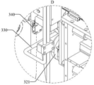
In some embodiments, as shown in fig. 4, the detection head apparatus 300 defines a head module B, and the automatic positioning mechanism 310, the automatic sealing mechanism 320, and the first gas channel 330 are part of the head module B.
The detection head device 300 further comprises a sixth driving mechanism 350 and a sensor 340; the sensor 340 is disposed on the head module B and configured to detect position information of the head module B; the sixth driving mechanism 350 is electrically connected to the sensor 340, and the sixth driving mechanism 350 is configured to drive the head module B to move and to configure the position of the head module B based on the position information from the sensor 340.
In this way, the sixth driving mechanism 350 configures the position of the head module B based on the position information of the head module B detected by the sensor 340, and it is possible to achieve matching adjustment of the position of the head module B according to the positions of the pipe joints 21 of the liners 20 of different models, so that the leak detection apparatus can be applied to leak detection of liners 20 of different models.
For example, if no trace gas is detected in the gas extracted from the cavity of the inner container 20, the sealing performance of the water inlet pipe joint and the water outlet pipe joint of the inner container 20 is considered to be good. If trace gas is detected from the gas extracted from the cavity of the inner container 20, it indicates that the joints of the water inlet pipe and the water outlet pipe of the inner container 20 are not sealed well, or the sealing head (specifically, for example, a plug) is not in good butt joint with the joints of the water inlet pipe and the water outlet pipe. Aiming at the condition that a sealing head (such as a plug) is not well butted with a joint of a water inlet pipe and a water outlet pipe, the leak detection device can be adjusted through the following steps based on the structure:
control the clamp assembly 311 to open;
after the sixth driving mechanism 350 controls the head module B to ascend for a specified distance, the head module B is controlled to slowly descend to gradually approach to the upper edge of one of the pipe joints 21 (such as the water inlet nut) until the signal of the sensor 340 (specifically, the laser sensor 340) is ON, and the position at this time is recorded;
the sixth driving mechanism 350 controls the head module B to continue to descend so as to gradually approach the lower edge of the pipe joint 21 (such as a water inlet nut) until the signal of the sensor 340 (specifically, the laser sensor 340) is OFF, and records the position at this time;
calculating the middle position according to the two recorded position information (namely the positions of the upper edge and the lower edge);
controlling the automatic sealing mechanism 320 to seal the pipe joint 21 and re-detecting the trace gas in the cavity of the inner container 20.
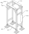
In some embodiments, as shown in FIG. 5, the leak detection apparatus further comprises a frame 400, the frame 400 comprising a top frame 410 and side frames 420, the top frame 410 and the side frames 420 enclosing an intraframe space; the lifting clamping device 100 is connected to the top frame 410, the jacking device 200 is accommodated in the space in the frame, the jacking device 200 is located below the lifting clamping device 100, and the detection head device 300 is connected to the side frame 420. Therefore, the integrated assembly of the leakage detection device is realized, and the positioning accuracy of the inner container 20 and the coordination precision among various mechanisms are more facilitated.
More specifically, the top frame 410 is provided with a first connecting plate 411, and the first base 131 is connected to the two first connecting plates 411 of the top frame 410 at positions on both sides of the through hole. Thus, the first base 131 abuts on the top frame 410, and the second base 132 and the clasping mechanism 120 on the second base 132 are suspended on the top frame 410. The side frame 420 is provided with a second connecting plate 4211, the detection head device 300 is provided with a fixing plate 360, and the fixing plate 360 is connected with the second connecting plate 4211, so that the detection head device 300 is approximately positioned at the side of the automatic positioning tool a.
Further optionally, as shown in fig. 5, the side frame 420 includes a support 421, a pull rod 422 is further disposed between the supports 421 of the side frame 420, and the pull rod 422 plays a role of a reinforcing rib, so that firmness and stability of the frame 400 can be further enhanced, and shaking of the frame 400 is reduced.
Further alternatively, as shown in fig. 5, an adjusting plate 423 is provided at the bottom of the support 421 of the side frame 420, and may be used to adjust the height of the frame 400 to adjust the levelness of the frame 400.
In some embodiments, the first gas channel 330 is, for example, a gas pipe, which can be used to connect to a tracer gas supply station, and the gas pipe is provided with an exhaust structure (such as a nozzle or a spray head) along which tracer gas supplied from the gas supply station is ultimately exhausted. The exhaust structure is mounted on the detection head part, or the exhaust structure is connected with the sealing head so that the relative position between the exhaust structure and the sealing head is approximately constant, and when the pipe joint 21 is sealed, the exhaust structure and the position to be detected are positioned, for example, the exhaust structure corresponds to the position to be detected, so that the tracer gas can be directly discharged to the position to be detected, and the exhaust position is more accurate.
One specific embodiment:
as shown in fig. 1, the present embodiment provides a leak detection apparatus including: the lifting clamping device 100, the jacking device 200, the detection head device 300 and the frame 400.
As for the lifting clamp device 100, as shown in fig. 2:
the main structure of the lifting clamping device 100 is fixed on the frame 400 through the first base 131, and when the lifting clamping device 100 works, the first motor 111 drives the first gear to further drive the first rack 113 to move, and the movement of the first rack 113 is guided through the first guide rail 114, so that the vertical movement of the clamping mechanism 120 of the lifting clamping device 100 is realized. Mechanical stoppers 115 are disposed on both sides of the first rail 114 to prevent the first rack 113 from moving beyond the stroke.
After the first rack 113 moves to the designated position, the second motor 1221 drives the second gear 1222 to further drive the second rack 1223 to move, the movement of the second rack 1223 is guided by the second guide rail 1224, and the clamping mechanism 120 is enabled to clamp the inner container 20.
The clasping mechanism 120 is specifically configured to clasp the inner container 20 via four rollers 1214 for preventing the inner container 20 from toppling over. The roller 1214 is connected to the first linear bearing 1212 and the guide shaft 1211, and the mechanism including the roller 1214 can float up and down.
With regard to the jacking device 200, as shown in fig. 3:
the first supporting block 201 is used for lifting the liner 20 to a designated height, the first supporting block 201 is specifically arranged on the bearing seat 203, the ascending and descending movement of a mechanism comprising the first supporting block 201 and the bearing seat 203 is realized through the expansion and contraction of a piston rod of an air cylinder (namely, the third driving piece 202), the movement of the mechanism is guided through the guide rod 208 and the second linear bearing 207, and the mechanism is fixed on the transmission belt connecting seat 204 by using the support rod 205.
As for the detection head device 300, as shown in fig. 4:
the whole detection head device 300 is fixed ON the frame 400 through the fixing plate 360, after the single-shaft manipulator (i.e., the sixth driving mechanism 350) drives the head module B to move up and down to a specified position, the first electric cylinder 3121 drives the mechanism (e.g., the clamp assembly 311) ON the third guide rail 3122 to advance to the specified position, at this time, the signal of the sensor 340 is "ON", the cylinder fingers (i.e., the second positioning block 3112) are closed, the second positioning block 3112 and the first positioning block 3111 clamp the two pipe joints 21, so as to realize the positioning of the pipe joints 21, it can be understood that, in the process of closing the second positioning block 3112 and the first positioning block 3111, the inner container 20 can be properly driven to rotate relative to the bearing seat 203 to adjust the position of the pipe joints 21, so as to realize the automatic circumferential alignment of the inner container 20.
The second electric cylinder 3221 drives the detection head part 321 to advance through the third linear bearing 3222 and the guide rod 3223, and after the two pipe joints 21 are butted in place, the pipe joints 21 are sealed, and the first gas channel 330 sprays helium (i.e., trace gas) to start detection.
Regarding the frame 400 structure, as shown in fig. 5:
the frame 400 is formed by welding the support 421 using a square pipe, welding the first connection plate 411 to the top frame 410, and welding the second connection plate 4211 to the side frame 420. Two adjacent supports 421 are connected to pull rod 422, play the strengthening rib effect, prevent that leak hunting device from rocking. The whole leakage detection device can be adjusted in height and level through an adjusting plate 423 at the bottom of the support 421.
The leak detection device provided by the scheme can be used for automatically detecting the tightness of the inner container 20 of equipment such as a water heater and the like. Mainly comprises four large structures, namely a lifting clamping device 100, a jacking device 200, a detection head device 300 and a frame 400. The detection process comprises the following steps:
1) after the inner container 20 reaches the detection station, the lifting clamping device 100 descends to reach a designated position, and the clamping mechanism 120 of the lifting clamping device 100 clamps the inner container 20 to prevent the inner container 20 from toppling;
2) the first positioning block 3111 and the second positioning block 3112 of the detection head device 300 extend out, so that the pipe joint 21 is limited between the first positioning block 3111 and the second positioning block 3112, and the rotation of the inner container 20 can be limited to a certain extent;
3) jacking by the jacking device 200 to jack the liner 20 to a specified height;
4) the first positioning block 3111 and the second positioning block 3112 in the detection head device 300 clamp the pipe joint 21;
5) the sealing head (i.e., the plug) of the detection head device 300 extends out to be abutted with the pipe joint 21, so that the pipe joint 21 is sealed;
6) evacuating the liner 20 (e.g., evacuating the liner 20 along the second gas passage 324), and spraying helium gas to the tube connector 21 (e.g., spraying helium gas to the tube connector 21 along the first gas passage 330);
7) the gas drawn out of the inner container 20 is detected.
If the vacuumizing structure does not detect helium, the pipe joint 21 of the inner container 20 is well sealed; if helium is detected, it is indicated that the pipe joint 21 of the inner container 20 is not sealed well or the plug is not in good abutment with the pipe joint 21 of the inner container 20.
If it is determined that the plug is not well butted against the pipe joint 21 of the inner container 20, the following steps are performed:
1. control the clamp assembly 311 to open;
2. after the sixth driving mechanism 350 controls the head module B to ascend for a specified distance, the head module B is controlled to slowly descend to gradually approach to the upper edge of one of the pipe joints 21 (such as the water inlet nut) until the signal of the sensor 340 (specifically, the laser sensor 340) is ON, and the position at this time is recorded;
3. the sixth driving mechanism 350 controls the head module B to continue to descend so as to gradually approach the lower edge of the pipe joint 21 (such as a water inlet nut) until the signal of the sensor 340 (specifically, the laser sensor 340) is OFF, and records the position at this time;
4. calculating the middle position according to the two recorded position information (namely the positions of the upper edge and the lower edge);
5. return to step 5) described above.
The leak detection device provided by the specific embodiment replaces manual operation with an automatic structure, saves manpower, improves the automation degree of a production line, achieves the purpose of leak detection, has less helium loss rate, and has lower detection cost while considering detection precision.
As shown in fig. 1, another aspect of the present application provides a liner production line, including: a conveyor belt 30 and a leak detection apparatus as in any of the embodiments described above.
The conveyor belt 30 is positioned to convey the liner 20; the automatic positioning tooling a of the leak detection apparatus is configured to pick up the liner 20 to be leak detected from the conveyor belt 30.
Further, as shown in fig. 3, the production line of the liner further includes a positioning seat 40, the positioning seat 40 is located on the conveyor 30 and can move along with the conveyor 30; the positioning seat 40 comprises second supporting blocks 41 distributed circumferentially around an avoidance area 42, and the second supporting blocks 41 can be used for supporting the liner 20; the escape area 42 can be used for the passage of a lifting device 200 of the leak detection device.
It will be appreciated that the leak detection apparatus may be individually provided with an evacuation detection device (e.g., an evacuation detection device capable of connecting to second gas path 324 and detecting the evacuated gas component) and/or a trace gas supply (e.g., a trace gas supply capable of connecting to the first gas path); alternatively, a vacuum detection device (e.g., a vacuum detection device that can be connected to the second gas channel 324 and detects the drawn gas component) and/or a trace gas supply station (e.g., a trace gas supply station that can be connected to the first gas channel) may be disposed in the liner production line, and one or more leak detection devices may be connected to the vacuum detection device and/or the trace gas supply station in the liner production line.
The production line of inner bag that this embodiment provided replaces manual work with automated structure, uses manpower sparingly, improves production line automation degree.
While the present application has been described with reference to several exemplary embodiments, it is understood that the terminology used is intended to be in the nature of words of description and illustration, rather than of limitation. As the present application may be embodied in several forms without departing from the spirit or essential characteristics thereof, it should also be understood that the above-described embodiments are not limited by any of the details of the foregoing description, but rather should be construed broadly within its spirit and scope as defined in the appended claims, and therefore all changes and modifications that fall within the meets and bounds of the claims, or equivalences of such meets and bounds are therefore intended to be embraced by the appended claims.
Claims (11)
1. A leak detection device which can be used for detecting the leak of an inner container, comprising:
the automatic positioning tool comprises a lifting clamping device and a jacking device, the lifting clamping device comprises a clamping mechanism and a first driving mechanism capable of driving the clamping mechanism to perform lifting motion, the clamping mechanism is configured to clamp the liner, the clamping mechanism comprises at least two clamping claw parts and a second driving mechanism, the clamping claw parts are arranged at intervals, each clamping claw part is provided with a floating part, each floating part can perform lifting motion relative to the corresponding clamping claw part, the second driving mechanism is connected with the corresponding clamping claw part, and the second driving mechanism is configured to drive at least one clamping claw part to move so as to enable the clamping claw parts to approach or depart from each other, the jacking device is configured to support the inner container and drive the inner container to do lifting movement;
the detection head device comprises an automatic positioning mechanism, an automatic sealing mechanism and a first gas channel, wherein the automatic positioning mechanism is configured to be capable of positioning a pipe joint of the inner container, the automatic sealing mechanism is configured to be capable of sealing the pipe joint, and the first gas channel is arranged to be capable of being used for conveying tracer gas to a position to be detected on the outer surface of the inner container.
2. Leak detection apparatus according to claim 1, wherein said first drive mechanism comprises:
a first driving member;
the first rotating piece can rotate under the driving of the first driving piece;
the clamping mechanism is connected with the first moving piece and can perform lifting motion under the driving of the first moving piece;
the first guide rail is connected with the first moving part and can guide the movement of the first moving part;
the two sides of the first guide rail are respectively provided with a limiting piece, and the limiting pieces can be used for abutting against the first moving piece to limit the movement stroke of the first moving piece.
3. Leak detection apparatus according to claim 1 or 2,
one or more rollers are arranged on the floating piece, and the rollers are rotatably connected with the floating piece;
the clamping jaw part comprises one or more guide shafts, the floating part can move along the axial direction of the guide shafts, and a first linear bearing is arranged between the floating part and the guide shafts;
the second driving mechanism comprises a second driving piece, a second rotating piece and a second guide rail, the clamping claw parts are arranged on the second guide rail and can slide along the second guide rail, each clamping claw part is respectively provided with a second moving piece, the second rotating piece is in tooth transmission or spiral transmission fit with the second moving pieces of at least two clamping claw parts, and the second rotating piece is connected with the second driving piece and can rotate under the driving of the second driving piece;
the lifting clamping and holding device is limited by a first base and a second base, the first driving mechanism is arranged on the first base, the second base is connected with the first driving mechanism and can be driven by the first driving mechanism, and the clamping and holding mechanism is arranged on the second base.
4. Leak detection apparatus according to claim 1 or 2, wherein the jacking means comprises:
the first supporting block is used for supporting the inner container;
the third driving piece is configured to drive the first supporting block to do lifting motion;
and the bearing seat is connected with the first supporting block and the third driving piece, so that the first supporting block and the third driving piece can rotate relatively.
5. The leak detection apparatus as defined in claim 4, wherein the jacking means further comprises:
a transmission belt connecting seat;
the supporting rod is connected with the conveying belt connecting seat;
the third base is connected with the supporting rod, a second linear bearing is arranged on the third base, a guide rod penetrates through the second linear bearing, and the guide rod is connected with the bearing seat;
the third driving member is mounted on the third base.
6. Leak detection apparatus according to claim 1 or 2,
the automatic positioning mechanism comprises a clamp assembly, a third driving mechanism and a fourth driving mechanism, wherein the third driving mechanism is configured to drive the clamp assembly to move so as to configure the position of the clamp assembly, and the fourth driving mechanism is configured to drive the clamp assembly to clamp or expand;
the automatic sealing mechanism comprises a sealing head and a fifth driving mechanism, wherein the fifth driving mechanism is configured to drive the sealing head to move, and the sealing head can seal or open the pipe joint through movement.
7. Leak detection apparatus according to claim 6,
the clamp assembly comprises a first positioning block and a second positioning block, the first positioning block and the second positioning block are oppositely arranged, and an accommodating part for accommodating the pipe joint is formed between the first positioning block and the second positioning block, wherein one of the first positioning block and the second positioning block is fixedly arranged, the other one of the first positioning block and the second positioning block is a pneumatic finger integrally arranged with the fourth driving mechanism, and the pneumatic finger can move to increase or decrease the distance between the first positioning block and the second positioning block;
a second gas channel penetrates through the sealing head, and when the sealing head seals the pipe joint, the second gas channel is communicated with the space in the inner container;
the automatic sealing mechanism is limited by a detection head part, the sealing heads are arranged on the detection head part, the number of the sealing heads on the detection head part is 2, the sealing heads are used for correspondingly sealing a water inlet pipe joint and a water outlet pipe joint on the inner container, and the fifth driving mechanism is connected with the detection head part and drives the detection head part to move.
8. Leak detection apparatus according to claim 1 or 2,
the detection head device is limited with a head module, and the automatic positioning mechanism, the automatic sealing mechanism and the first gas channel are part of the head module;
the detection head device also comprises a sixth driving mechanism and a sensor;
the sensor is arranged on the head module and is configured to detect the position information of the head module;
the sixth driving mechanism is electrically connected with the sensor, is configured to drive the head module to move, and can configure the position of the head module according to the position information from the sensor.
9. Leak detection apparatus according to claim 1 or 2, further comprising:
the frame comprises a top frame and side frames, and an in-frame space is enclosed by the top frame and the side frames;
the lifting clamp is connected with the top frame, the jacking device is accommodated in the space in the frame, the jacking device is located below the lifting clamp, and the detection head device is connected with the side frame.
10. A production line of inner containers, characterized by comprising:
a conveyor belt, which is configured to convey the liner;
leak detection apparatus as claimed in any one of claims 1 to 9, the automated positioning tooling of the leak detection apparatus being arranged to pick up the liner to be leak detected from the conveyor belt.
11. The liner production line of claim 10, further comprising:
the positioning seat is positioned on the conveying belt and can move along with the conveying belt;
the positioning seat comprises second supporting blocks which are distributed circumferentially around an avoidance area, and the second supporting blocks can be used for supporting the liner;
the avoiding area can be used for a jacking device of the leak detection device to penetrate through.
Priority Applications (1)
| Application Number | Priority Date | Filing Date | Title |
|---|---|---|---|
| CN202123388003.1U CN215755145U (en) | 2021-12-30 | 2021-12-30 | Production line of leak hunting device and inner bag |
Applications Claiming Priority (1)
| Application Number | Priority Date | Filing Date | Title |
|---|---|---|---|
| CN202123388003.1U CN215755145U (en) | 2021-12-30 | 2021-12-30 | Production line of leak hunting device and inner bag |
Publications (1)
| Publication Number | Publication Date |
|---|---|
| CN215755145U true CN215755145U (en) | 2022-02-08 |
Family
ID=80095586
Family Applications (1)
| Application Number | Title | Priority Date | Filing Date |
|---|---|---|---|
| CN202123388003.1U Active CN215755145U (en) | 2021-12-30 | 2021-12-30 | Production line of leak hunting device and inner bag |
Country Status (1)
| Country | Link |
|---|---|
| CN (1) | CN215755145U (en) |
-
2021
- 2021-12-30 CN CN202123388003.1U patent/CN215755145U/en active Active
Similar Documents
| Publication | Publication Date | Title |
|---|---|---|
| CN108871702B (en) | Integral airtight and film airtight detection equipment in airtight detection equipment | |
| CN111331366B (en) | Assembly equipment and process of integrated sprayer | |
| CN105181261A (en) | Welding tightness detection machine and method using detection machine to detect welding tightness | |
| CN115773852B (en) | Biopsy needle hose air tightness test tool and test mode | |
| CN217237111U (en) | Detection device | |
| CN112033611A (en) | Automatic check out test set of leakproofness | |
| CN215755145U (en) | Production line of leak hunting device and inner bag | |
| CN114001871A (en) | Full-automatic leak hunting machine based on automobile axle housing reinforcing ring welding seam detects | |
| CN117340603B (en) | Efficient automatic assembly and detection production line for temperature control valve | |
| CN117161560B (en) | Coiled material banding welding set | |
| CN111452371B (en) | Detection cleaner station based on medical infusion line part assembly detection machine | |
| CN112846497A (en) | Vacuum cup vacuum welding machine | |
| CN110231128B (en) | Helium leak detection mechanism | |
| CN211687294U (en) | Double-station air tightness detection device | |
| CN220206973U (en) | Negative pressure helium detection device applicable to battery cell | |
| CN210293576U (en) | Helium leakage detection mechanism | |
| CN115401434A (en) | Ball valve assembly production line | |
| CN114544098B (en) | Automatic product transfer system | |
| CN215465799U (en) | Battery case upper cover plate gluing and baking device and system | |
| CN110261044B (en) | Air tightness detection equipment | |
| CN212708103U (en) | Assembly station based on medical infusion line part assembly detection machine | |
| CN110341835B (en) | Vehicle air conditioner air outlet assembly fixture | |
| CN114441110A (en) | Helium leakage detection equipment for battery top cover and working method of helium leakage detection equipment | |
| CN112665792B (en) | Battery collet welding seam leak hunting device | |
| CN216178209U (en) | Injection molding workpiece sleeve sealing ring device |
Legal Events
| Date | Code | Title | Description |
|---|---|---|---|
| GR01 | Patent grant | ||
| GR01 | Patent grant |