CN215721243U - Synthesize pipeline antidetonation gallows - Google Patents
Synthesize pipeline antidetonation gallows Download PDFInfo
- Publication number
- CN215721243U CN215721243U CN202122105685.4U CN202122105685U CN215721243U CN 215721243 U CN215721243 U CN 215721243U CN 202122105685 U CN202122105685 U CN 202122105685U CN 215721243 U CN215721243 U CN 215721243U
- Authority
- CN
- China
- Prior art keywords
- block
- bolt
- mounting
- fixedly connected
- hanger
- Prior art date
- Legal status (The legal status is an assumption and is not a legal conclusion. Google has not performed a legal analysis and makes no representation as to the accuracy of the status listed.)
- Active
Links
Images


Abstract
The utility model discloses an integrated pipeline anti-seismic support and hanger frame, which comprises a first mounting frame, wherein limiting columns are arranged at two sides of the center line of the top end of the first mounting frame; first mounting bracket top both sides are provided with first stop device, second stop device respectively, first mounting bracket terminal both sides are provided with the second connecting piece respectively, second connecting piece top is provided with the second mounting bracket. The shock absorption device has the advantages that the shock absorption effect is good, the joints of the pipelines are not easy to damage, the pipelines with different diameters can be quickly installed in real time, and the application range is wide.
Description
Technical Field
The utility model relates to the technical field of supports and hangers, in particular to an anti-seismic support and hanger for an integrated pipeline.
Background
A pipe is a device for transporting a gas, liquid or fluid with solid particles connected by pipes, pipe couplings, valves, etc. The design and the form of the pipe support structure of the pipeline support and hanger are selected as an important component in the design of a pipeline system, the pipe support can balance the acting force of a piping system except for supporting the weight of the pipeline, the displacement of the pipeline is limited and the vibration is absorbed, when the pipeline system is designed, the pipe support which is reasonable in structure is correctly selected and arranged, the stress distribution of the pipeline and the acting force on a pipe frame can be improved, the safe operation of the pipeline system is ensured, and the service life of the pipeline system is prolonged.
The supporting structure is used as a supporting structure of the pipeline, the running performance and the arrangement requirement of the pipeline are met, the existing supporting and hanging frame is simple in structure, the installation platform is required to be replaced aiming at pipelines with different diameters, time and labor are wasted, and even some supporting and hanging frames are not suitable for the pipeline diameter condition and cannot be used.
When the applicant applies the utility model, through retrieval, the applicant finds that a Chinese patent discloses a comprehensive pipeline anti-seismic support and hanger, the application number of which is '201921493622.7', the patent mainly comprises that a first shock absorption mechanism is connected between two fixed seats and a fixed rod, the first shock absorption mechanism reduces the shock transmitted from the fixed seats to the fixed rod, so that the shock transmitted from the fixed rod to a supporting beam is reduced, and a pipeline is erected on the supporting beam, so that the shock of the pipeline is reduced; a second cushioning mechanism is connected between the fixed rod and the supporting beam, and reduces the vibration transmitted to the supporting beam by the fixed rod, so that the vibration erected on the supporting beam is reduced; the fixed rod comprises an upper fixed rod and a lower fixed rod which is in threaded connection with the lower part of the upper fixed rod, so that the height of the fixed rod is adjustable, and pipelines in different occasions can be conveniently installed and fixed; the fixed seat is fixedly connected with the embedded part, so that the installation stability of the utility model is further improved; the support rod reduces the vibration of the fixed rod and improves the installation stability of the utility model; a plurality of recesses have been seted up on supporting beam, and the recess slides and is connected with the slider, is fixed with the clamp that is used for fixed pipeline on the slider, and the both ends of slider are fixed with the third bradyseism spring, have reduced the vibrations that are used for the clamp of fixed pipeline, but can't carry out the scene to the different pipeline of diameter and install the processing fast.
SUMMERY OF THE UTILITY MODEL
The utility model aims to solve the defect that pipelines with different diameters cannot be installed in the prior art, and provides an anti-seismic support and hanger for a comprehensive pipeline.
In order to achieve the purpose, the utility model adopts the following technical scheme: an anti-seismic support and hanger for a comprehensive pipeline comprises a first mounting frame, wherein limiting columns are arranged on two sides of a center line of the top end of the first mounting frame, first connecting pieces are arranged on two sides of the front end of the first mounting frame respectively and comprise first connecting blocks and second connecting blocks, a first spring is arranged between each first connecting block and each second connecting block, a second mounting frame is arranged at the other end of each first connecting piece, and a fixing column is arranged at the top end of each second mounting frame; a first limiting device and a second limiting device are respectively arranged on two sides of the top end of the first mounting frame, the first limiting device comprises a first fixing block, a second bolt is arranged in the first fixing block, a first limiting block is arranged at a position, close to the middle of the first mounting frame, of the second bolt, the other end of the second bolt is fixedly connected with a first rotating handle, the second limiting device comprises a second fixing block, a third bolt is arranged in the second fixing block, a second limiting block is arranged at a position, close to the middle of the first mounting frame, of the third bolt, and the other end of the third bolt is fixedly connected with a second rotating handle; the utility model discloses a buffer structure, including first mounting bracket, first spliced pole, second connecting piece, buffer board middle part bottom, second spliced pole, second connecting piece top are provided with the second connecting piece respectively, second connecting piece top is provided with the second mounting bracket, the second connecting piece includes first spliced pole, first spliced pole top fixed connection in second mounting bracket, first spliced pole other end fixedly connected with buffering box, be provided with the cavity in the buffering box, be provided with the buffer board in the cavity, buffer board both sides bottom is provided with the second spring, second spring other end fixed connection is in the cavity bottom, buffer board middle part bottom is provided with the second spliced pole, second spliced pole other end fixedly connected with first mounting bracket lateral wall.
As a further description of the above technical solution:
first connecting block one end fixed connection is in first mounting bracket lateral wall, first connecting block other end fixedly connected with first spring, first spring other end fixedly connected with second connecting block, second connecting block other end fixedly connected with second mounting bracket.
As a further description of the above technical solution:
the second mounting bracket comprises a third mounting block, and a first bolt is arranged on the third mounting block.
As a further description of the above technical solution:
the bottom end of the third mounting block is provided with a fourth mounting block, the bottom end of the fourth mounting block is provided with a nut matched with the first bolt, and a gasket is arranged between the nut and the fourth mounting block.
As a further description of the above technical solution:
a first screw hole is formed in the first fixing block and matched with the second bolt.
As a further description of the above technical solution:
first stopper fixed connection is in the second bolt, and fixed angle is 45.
As a further description of the above technical solution:
and a second screw hole is formed in the second fixing block and matched with a third bolt.
As a further description of the above technical solution:
the second limiting block is fixedly connected to the third bolt, and the fixed angle is 135 degrees.
The utility model has the following beneficial effects:
1. compared with the prior art, this synthesize pipeline antidetonation gallows has included first connecting piece and second connecting piece, and the bradyseism is effectual, has reduced the circumstances that the junction of pipeline takes place to damage.
2. Compared with the prior art, this synthesize a pipeline antidetonation gallows top second mounting bracket sound construction is stable, and the fixed column can be guaranteed to be connected with the top junction is stable, can not have a gallows obscission to take place when vibrations.
3. Compared with the prior art, the comprehensive pipeline anti-seismic support and hanger can be rapidly installed in real time aiming at pipelines with different diameters, and the application range is wide.
Drawings
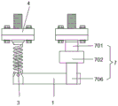
FIG. 1 is a front view of an integrated pipeline seismic support and hanger according to the present invention;
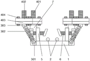
FIG. 2 is a schematic structural view of a first mounting bracket of an anti-seismic support and hanger for an integrated pipeline according to the present invention;
FIG. 3 is a side view of an integrated pipeline seismic support and hanger according to the present invention;
FIG. 4 is a schematic structural view of a cushioning box of an anti-seismic support and hanger for a composite pipeline according to the present invention;
fig. 5 is a schematic structural view of a second mounting bracket of an integrated pipeline seismic support and hanger according to the present invention.
Illustration of the drawings:
1. a first mounting bracket; 2. a limiting column; 3. a first connecting member; 301. a first connection block; 302. a first spring; 303. a second connecting block; 4. a second mounting bracket; 401. fixing a column; 402. a third mounting block; 403. a fourth mounting block; 404. a first bolt; 405. a gasket; 406. a nut; 5. a first limiting device; 501. a first fixed block; 502. a second bolt; 503. a first rotating handle; 504. a first stopper; 505. a first screw hole; 6. a second limiting device; 601. a second fixed block; 602. a third bolt; 603. a second rotating handle; 604. a second limiting block; 605. a second screw hole; 7. a second connecting member; 701. a first connecting column; 702. a buffer box; 703. a cavity; 704. a second spring; 705. a buffer plate; 706. a second connecting column.
Detailed Description
The technical solutions in the embodiments of the present invention will be clearly and completely described below with reference to the drawings in the embodiments of the present invention, and it is obvious that the described embodiments are only a part of the embodiments of the present invention, and not all of the embodiments. All other embodiments, which can be derived by a person skilled in the art from the embodiments given herein without making any creative effort, shall fall within the protection scope of the present invention.
In the description of the present invention, it should be noted that the terms "center", "upper", "lower", "left", "right", "vertical", "horizontal", "inner", "outer", etc., indicate orientations or positional relationships based on the orientations or positional relationships shown in the drawings, and are only for convenience of description and simplicity of description, but do not indicate or imply that the device or element being referred to must have a particular orientation, be constructed and operated in a particular orientation, and thus, should not be construed as limiting the present invention; the terms "first," "second," and "third" are used for descriptive purposes only and are not to be construed as indicating or implying relative importance, and furthermore, unless otherwise explicitly stated or limited, the terms "mounted," "connected," and "connected" are to be construed broadly and may be, for example, fixedly connected, detachably connected, or integrally connected; can be mechanically or electrically connected; they may be connected directly or indirectly through intervening media, or they may be interconnected between two elements. The specific meanings of the above terms in the present invention can be understood in specific cases to those skilled in the art.
Referring to fig. 1-5, one embodiment of the present invention is provided: the utility model provides a synthesize pipeline antidetonation gallows, including first mounting bracket 1, 1 top central line both sides position of first mounting bracket is provided with spacing post 2, 1 front end both sides of first mounting bracket are provided with first connecting piece 3 respectively, first connecting piece 3 includes first connecting block 301, second connecting block 303, 301 one end fixed connection of first connecting block in 1 lateral wall of first mounting bracket, 301 other end fixed connection of first connecting block has first spring 302, 302 other end fixed connection of first spring has second connecting block 303, 303 other end fixed connection of second connecting block has second mounting bracket 4.
The second mounting bracket 4 includes a third mounting block 402, and a first bolt 404 is disposed on the third mounting block 402. A fourth mounting block 403 is arranged at the bottom end of the third mounting block 402, a nut 406 matched with the first bolt 404 is arranged at the bottom end of the fourth mounting block 403, a gasket 405 is arranged between the nut 406 and the fourth mounting block 403, and a fixing column 401 is arranged at the top end of the second mounting frame 4;
first 1 top both sides of first mounting bracket are provided with first stop device 5 respectively, second stop device 6, first stop device 5 includes first fixed block 501, be provided with second bolt 502 in the first fixed block 501, second bolt 502 is provided with first stopper 504 near the position in the middle of first mounting bracket 1, second bolt 502 other end fixedly connected with first twist grip 503, be provided with first screw 505 in the first fixed block 501, first screw 505 and second bolt 502 phase-match, first stopper 504 fixed connection is in second bolt 502, and fixed angle is 45.
The second limiting device 6 comprises a second fixing block 601, a third bolt 602 is arranged in the second fixing block 601, a second limiting block 604 is arranged at a position, close to the middle of the first mounting frame 1, of the third bolt 602, a second rotating handle 603 is fixedly connected to the other end of the third bolt 602, a second screw hole 605 is arranged in the second fixing block 601, the second screw hole 605 is matched with the third bolt 602, the second limiting block 604 is fixedly connected to the third bolt 602, and the fixing angle is 135 degrees.
The two sides of the tail end of the first mounting rack 1 are respectively provided with a second connecting piece 7, the top end of the second connecting piece 7 is provided with a second mounting rack 4, the second connecting piece 7 comprises a first connecting column 701, the top end of the first connecting column 701 is fixedly connected with the second mounting rack 4, the other end of the first connecting column 701 is fixedly connected with a buffer box 702, a cavity 703 is formed in the buffer box 702, a buffer plate 705 is arranged in the cavity 703, the bottom ends of the two sides of the buffer plate 705 are provided with a second spring 704, the other end of the second spring 704 is fixedly connected to the bottom of the cavity 703, the bottom end of the middle of the buffer plate 705 is provided with a second connecting column 706, and the other end of the second connecting column 706 is fixedly connected with the side wall of the first mounting rack 1.
The working principle is as follows: the fixed column 401 on the top end of the second mounting rack 4 is embedded in the top wall, the first mounting rack 1 is connected with the second mounting rack 4 through the first connecting piece 3 and the second connecting piece 7, the first connecting piece 3 and the second connecting piece 7 reduce the vibration transmitted to the first mounting rack 1 by the second mounting rack 4, so that pipelines erected on the first mounting rack 1 are reduced, when the pipelines are erected, the pipelines are placed on the limiting column 2, the first rotating handle (503) is screwed by hands, the first limiting block (504) is adjusted by the second rotating handle (603), the second limiting block (604), the pipelines are fixed on the first mounting rack 1, and the pipelines with different diameters are quickly installed and fixed.
Finally, it should be noted that: although the present invention has been described in detail with reference to the foregoing embodiments, it will be apparent to those skilled in the art that modifications may be made to the embodiments or portions thereof without departing from the spirit and scope of the utility model.
Claims (8)
1. The utility model provides a synthesize pipeline antidetonation gallows, includes first mounting bracket (1), its characterized in that: limiting columns (2) are arranged on two sides of a center line of the top end of the first mounting frame (1), first connecting pieces (3) are arranged on two sides of the front end of the first mounting frame (1) respectively, each first connecting piece (3) comprises a first connecting block (301) and a second connecting block (303), a first spring (302) is arranged between each first connecting block (301) and each second connecting block (303), a second mounting frame (4) is arranged at the other end of each first connecting piece (3), and a fixing column (401) is arranged at the top end of each second mounting frame (4);
a first limiting device (5) and a second limiting device (6) are respectively arranged on two sides of the top end of the first mounting frame (1), the first limiting device (5) comprises a first fixing block (501), a second bolt (502) is arranged in the first fixing block (501), a first limiting block (504) is arranged at a position, close to the middle of the first mounting frame (1), of the second bolt (502), the other end of the second bolt (502) is fixedly connected with a first rotating handle (503), the second limiting device (6) comprises a second fixing block (601), a third bolt (602) is arranged in the second fixing block (601), a second limiting block (604) is arranged at a position, close to the middle of the first mounting frame (1), of the third bolt (602), and a second rotating handle (603) is fixedly connected to the other end of the third bolt (602);
two sides of the tail end of the first mounting rack (1) are respectively provided with a second connecting piece (7), a second mounting rack (4) is arranged at the top end of the second connecting piece (7), the second connecting piece (7) comprises a first connecting column (701), the top end of the first connecting column (701) is fixedly connected with the second mounting rack (4), the other end of the first connecting column (701) is fixedly connected with a buffer box (702), a cavity (703) is arranged in the buffer box (702), a buffer plate (705) is arranged in the cavity (703), the bottom ends of two sides of the buffer plate (705) are provided with second springs (704), the other ends of the second springs (704) are fixedly connected to the bottom of the cavity (703), the bottom end of the middle part of the buffer plate (705) is provided with a second connecting column (706), and the other end of the second connecting column (706) is fixedly connected with the side wall of the first mounting frame (1).
2. An integrated pipeline anti-seismic support and hanger as defined in claim 1, wherein: first connecting block (301) one end fixed connection is in first mounting bracket (1) lateral wall, first connecting block (301) other end fixedly connected with first spring (302), first spring (302) other end fixedly connected with second connecting block (303), second connecting block (303) other end fixedly connected with second mounting bracket (4).
3. An integrated pipeline anti-seismic support and hanger as defined in claim 1, wherein: the second mounting frame (4) comprises a third mounting block (402), and a first bolt (404) is arranged on the third mounting block (402).
4. An integrated pipeline anti-seismic support and hanger as defined in claim 3, wherein: the bottom end of the third mounting block (402) is provided with a fourth mounting block (403), the bottom end of the fourth mounting block (403) is provided with a nut (406) matched with the first bolt (404), and a gasket (405) is arranged between the nut (406) and the fourth mounting block (403).
5. An integrated pipeline anti-seismic support and hanger as defined in claim 1, wherein: a first screw hole (505) is formed in the first fixing block (501), and the first screw hole (505) is matched with the second bolt (502).
6. An integrated pipeline anti-seismic support and hanger as defined in claim 1, wherein: the first limiting block (504) is fixedly connected to the second bolt (502), and the fixed angle is 45 degrees.
7. An integrated pipeline anti-seismic support and hanger as defined in claim 1, wherein: and a second screw hole (605) is formed in the second fixing block (601), and the second screw hole (605) is matched with the third bolt (602).
8. An integrated pipeline anti-seismic support and hanger as defined in claim 1, wherein: the second limiting block (604) is fixedly connected to the third bolt (602), and the fixed angle is 135 degrees.
Priority Applications (1)
| Application Number | Priority Date | Filing Date | Title |
|---|---|---|---|
| CN202122105685.4U CN215721243U (en) | 2021-09-02 | 2021-09-02 | Synthesize pipeline antidetonation gallows |
Applications Claiming Priority (1)
| Application Number | Priority Date | Filing Date | Title |
|---|---|---|---|
| CN202122105685.4U CN215721243U (en) | 2021-09-02 | 2021-09-02 | Synthesize pipeline antidetonation gallows |
Publications (1)
| Publication Number | Publication Date |
|---|---|
| CN215721243U true CN215721243U (en) | 2022-02-01 |
Family
ID=80011486
Family Applications (1)
| Application Number | Title | Priority Date | Filing Date |
|---|---|---|---|
| CN202122105685.4U Active CN215721243U (en) | 2021-09-02 | 2021-09-02 | Synthesize pipeline antidetonation gallows |
Country Status (1)
| Country | Link |
|---|---|
| CN (1) | CN215721243U (en) |
-
2021
- 2021-09-02 CN CN202122105685.4U patent/CN215721243U/en active Active
Similar Documents
| Publication | Publication Date | Title |
|---|---|---|
| CN112413236B (en) | Novel assembled piping lane gallows of combatting earthquake | |
| CN211083103U (en) | Anti-seismic fixed support hanger | |
| CN216976004U (en) | High-strength assembly type damping support hanger | |
| CN215721243U (en) | Synthesize pipeline antidetonation gallows | |
| CN215061096U (en) | Multi-mode horizontal adjustment mounting bracket in pipe well | |
| CN204879068U (en) | A three -dimensional spring pipeline gallows | |
| CN203286148U (en) | Shock damping tube holder | |
| CN211039935U (en) | Anti-seismic connecting support assembly | |
| CN209213192U (en) | A kind of Pipe installing support frame | |
| CN208381498U (en) | A kind of vertical vibration damping antidetonation suspension and support based on disk spring | |
| CN212775988U (en) | Pipeline gallows installation device | |
| CN210687452U (en) | A antidetonation gallows for subway station room pipeline | |
| CN211693986U (en) | Anti-seismic support and hanger based on disk spring vibration reduction | |
| CN209054185U (en) | A kind of resistance to compression avoids curved suspension and support | |
| CN209398938U (en) | A kind of multi-functional antidetonation suspension and support | |
| CN209762433U (en) | anti-seismic support hanger with high-strength bearing performance | |
| CN219221490U (en) | Pipeline antidetonation gallows structure | |
| CN214197750U (en) | Screw fastener of anti-seismic support and hanger | |
| CN207064849U (en) | A kind of damping support of pipelines suitable for high-rise building | |
| CN212775987U (en) | Pipe gallery supporting and hanging frame | |
| CN216158491U (en) | Constant force dish spring gallows for boiler pipeline | |
| CN220470974U (en) | Anti-seismic bracket with strong load capacity | |
| CN215488059U (en) | Novel antidetonation gallows | |
| CN215371310U (en) | Pipeline antidetonation gallows | |
| CN216078620U (en) | Assembled antidetonation gallows of easily freely splicing |
Legal Events
| Date | Code | Title | Description |
|---|---|---|---|
| GR01 | Patent grant | ||
| GR01 | Patent grant |