CN215712589U - Vacuum dehydroxylation furnace for semiconductor quartz glass product - Google Patents
Vacuum dehydroxylation furnace for semiconductor quartz glass product Download PDFInfo
- Publication number
- CN215712589U CN215712589U CN202121990816.5U CN202121990816U CN215712589U CN 215712589 U CN215712589 U CN 215712589U CN 202121990816 U CN202121990816 U CN 202121990816U CN 215712589 U CN215712589 U CN 215712589U
- Authority
- CN
- China
- Prior art keywords
- rod
- furnace
- furnace body
- quartz glass
- vacuum dehydroxylation
- Prior art date
- Legal status (The legal status is an assumption and is not a legal conclusion. Google has not performed a legal analysis and makes no representation as to the accuracy of the status listed.)
- Active
Links
Images


Landscapes
- Furnace Charging Or Discharging (AREA)
Abstract
The utility model relates to the technical field of vacuum dehydroxylation furnaces, and discloses a vacuum dehydroxylation furnace for semiconductor quartz glass products, which comprises a base and a furnace body, wherein the furnace body is fixedly arranged on the upper surface of the base, two ends of the left side wall of the furnace body are respectively provided with a sliding chute, sliding rods are respectively arranged in the two sliding chutes in a sliding manner, a cover plate is arranged between the left ends of the two sliding rods, two ends of the cover plate are respectively rotatably connected with the corresponding sliding rods through rotating rods, two sides of the lower end of the cover plate are respectively and fixedly provided with a supporting plate, a placing frame is respectively placed on the surface of each of the two supporting plates, and the middle part of the upper surface of the furnace body is provided with a limiting mechanism for fixing the cover plate. The utility model can simultaneously carry out unloading and processing, greatly reduces the equipment downtime and improves the processing efficiency.
Description
Technical Field
The utility model relates to the technical field of vacuum dehydroxylation furnaces, in particular to a vacuum dehydroxylation furnace for semiconductor quartz glass products.
Background
After the quartz product is produced, the finished product needs to be heated to remove the hydroxyl compounds in the material, and the currently common dehydroxylation equipment is a vacuum dehydroxylation furnace, wherein the quartz product is placed inside the dehydroxylation furnace, and the hydroxyl compounds in the material are removed by heating and other chemical means.
Traditional semiconductor quartz glass is vacuum dehydroxylation furnace for goods, need lift off the rack that is equipped with the product after the dehydroxylation is ended, because just having processed, rack and product have higher temperature, unload and need consume more time, equipment needs to shut down longer time promptly, great reduction machining efficiency.
SUMMERY OF THE UTILITY MODEL
The utility model aims to solve the problems that in the prior art, a vacuum dehydroxylation furnace for semiconductor quartz glass products needs to be stopped for a long time for discharging, so that time is wasted, and the processing efficiency is greatly reduced.
In order to achieve the purpose, the utility model adopts the following technical scheme:
the utility model provides a vacuum dehydroxylation furnace for semiconductor quartz glass product, includes base and furnace body, the furnace body is fixed to be set up in the upper surface of base, the spout has all been seted up at the left side wall both ends of furnace body, two the inside of spout all slides and is provided with the slide bar, two be provided with the apron between the left end of slide bar, the both ends of apron all rotate with the slide bar that corresponds through the bull stick and be connected, the lower extreme both sides of apron are all fixed and are provided with the backup pad, two the rack has all been placed on the surface of backup pad, the upper surface middle part of furnace body is provided with fixedly the stop gear of apron.
Preferably, stop gear includes threaded rod and motor, the threaded rod rotates to set up in the upside the inside of spout, the upside the slide bar cup joints with the threaded rod screw thread, the upside the cavity is seted up on the right side of spout, the right-hand member of threaded rod extends to the inside of cavity, the fixed support frame that is provided with in upper surface middle part of furnace body, the lower surface of support frame rotates and is provided with the transfer line, the lower extreme of transfer line extends to the inside of cavity, the bevel gear, two have all been fixed to cup jointed to the right-hand member of threaded rod and the lower extreme of transfer line the bevel gear meshing is connected, the motor sets up in the upper surface of support frame, the output of motor and the upper end fixed connection of transfer line.
Preferably, the limiting mechanism comprises an electric push rod and a clamping block, a fixing frame is fixedly arranged in the middle of the upper surface of the furnace body, the electric push rod is fixedly arranged in the fixing frame, the clamping block is fixedly arranged at the tail end of a piston rod of the electric push rod, the lower end of the clamping block extends to the upper side in the sliding groove, a clamping groove is formed in the upper surface of the right end of the sliding rod, and the clamping block is matched with the clamping groove.
Preferably, the motor is fixedly connected with the support frame through a mounting frame.
Preferably, the lower side is fixedly provided with a fixed rod inside the chute, and the lower side is movably sleeved with the fixed rod.
Preferably, the upper surfaces of the two support plates are provided with anti-skid grains.
Preferably, both sides of the cover plate are fixedly provided with sealing rings.
Compared with the prior art, the utility model provides a vacuum dehydroxylation furnace for semiconductor quartz glass products, which has the following beneficial effects:
1. this semiconductor is vacuum dehydroxylation furnace for quartz glass article through rotating the apron, can exchange both sides rack position, can be promptly with treating processing and the product position interchange that is processed, can unload and process simultaneously promptly, great reduction equipment down time, improved machining efficiency.
2. This vacuum dehydroxylation furnace for semiconductor quartz glass product drives two bevel gears through the motor and rotates to drive the lead screw and rotate, the lead screw drives upside slide bar and removes to the spout that corresponds in, can make apron and the stable cooperation of furnace body promptly.
3. This semiconductor is vacuum dehydroxylation stove for quartz glass product, through promoting the apron to with the furnace body cooperation, then electric putter piston rod stretches out, promotes fixture block downstream and draw-in groove joint, can carry out spacingly promptly to the apron for apron and the stable cooperation of furnace body.
The parts which are not involved in the device are the same as or can be realized by adopting the prior art, the utility model can carry out unloading and processing simultaneously, thereby greatly reducing the equipment downtime and improving the processing efficiency.
Drawings
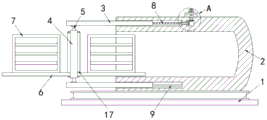
FIG. 1 is a schematic structural view of a vacuum dehydroxylation furnace for semiconductor quartz glass products according to the present invention;
FIG. 2 is an enlarged view of a portion A of FIG. 1;
FIG. 3 is a schematic structural view of another embodiment of a vacuum dehydroxylation furnace for semiconductor quartz glass articles according to the present invention.
In the figure: the furnace comprises a base 1, a furnace body 2, a sliding rod 3, a cover plate 4, a rotating rod 5, a supporting plate 6, a placing frame 7, a threaded rod 8, a fixing rod 9, a supporting frame 10, a transmission rod 11, a motor 12, a bevel gear 13, a fixing frame 14, an electric push rod 15, a clamping block 16 and a sealing ring 17.
Detailed Description
The technical solutions in the embodiments of the present invention will be clearly and completely described below with reference to the drawings in the embodiments of the present invention, and it is obvious that the described embodiments are only a part of the embodiments of the present invention, and not all of the embodiments.
In the description of the present invention, it is to be understood that the terms "upper", "lower", "front", "rear", "left", "right", "top", "bottom", "inner", "outer", and the like, indicate orientations or positional relationships based on the orientations or positional relationships shown in the drawings, are merely for convenience in describing the present invention and simplifying the description, and do not indicate or imply that the device or element being referred to must have a particular orientation, be constructed and operated in a particular orientation, and thus, should not be construed as limiting the present invention.
Example 1
Referring to fig. 1-2, a vacuum dehydroxylation furnace for semiconductor quartz glass products, including base 1 and furnace body 2, furnace body 2 is fixed to be set up in the upper surface of base 1, the spout has all been seted up at the left side wall both ends of furnace body 2, the inside of two spouts all slides and is provided with slide bar 3, be provided with apron 4 between the left end of two slide bars 3, the both ends of apron 4 all rotate with corresponding slide bar 3 through bull stick 5 and are connected, the lower extreme both sides of apron 4 all fixedly are provided with backup pad 6, rack 7 has all been placed on the surface of two backup pad 6, the upper surface middle part of furnace body 2 is provided with the stop gear of fixed apron 4.
Stop gear includes threaded rod 8 and motor 12, threaded rod 8 rotates and sets up in the inside of upside spout, upside slide bar 3 cup joints with 8 screw threads of threaded rod, the cavity is seted up on the right side of upside spout, the right-hand member of threaded rod 8 extends to the inside of cavity, the fixed support frame 10 that is provided with in upper surface middle part of furnace body 2, the lower surface rotation of support frame 10 is provided with transfer line 11, the lower extreme of transfer line 11 extends to the inside of cavity, bevel gear 13 has all been cup jointed to the right-hand member of threaded rod 8 and the lower extreme of transfer line 11, two bevel gear 13 meshing connections, motor 12 sets up in the upper surface of support frame 10, motor 12's output and transfer line 11's upper end fixed connection.
The motor 12 is fixedly connected with the support frame 10 through a mounting frame, so that the motor 12 is more stably connected with the support frame 10.
The inside of downside spout all is fixed and is provided with dead lever 9, and downside slide bar 3 cup joints with the activity of dead lever 9 for the removal that downside slide 3 can be stable.
The upper surfaces of the two supporting plates 6 are provided with anti-skid grains, so that the placing frame 7 can be stably placed on the upper surface of the supporting plate 6.
And sealing rings 17 are fixedly arranged on two sides of the cover plate 4, so that the sealing performance between the cover plate 4 and the furnace body 2 is improved.
When the automatic machining device is used, a worker rotates the cover plate 4 to interchange the positions of the placing frames 7 on the two sides, namely, the positions of products to be machined and well machined are interchanged, then a power supply of the motor 12 is switched on, the motor 12 drives the transmission rod 11 to rotate, namely, the two bevel gears 13 are driven to rotate in a meshed mode, so that the threaded rod 8 is driven to rotate, the threaded rod 8 drives the upper side sliding rod 3 to move towards the inside of the sliding groove, the cover plate 4 is tightly matched with the furnace body 2, a workpiece to be machined is pushed into the furnace body, at the moment, the workpiece can be machined while being unloaded, the equipment can be greatly shortened in downtime, and the machining efficiency is improved.
Example 2
Referring to fig. 3, a vacuum dehydroxylation furnace for semiconductor quartz glass products, including base 1 and furnace body 2, furnace body 2 is fixed to be set up in the upper surface of base 1, the spout has all been seted up at furnace body 2's left side wall both ends, the inside of two spouts all slides and is provided with slide bar 3, be provided with apron 4 between two slide bar 3's the left end, apron 4's both ends are all rotated with the slide bar 3 that corresponds through bull stick 5 and are connected, apron 4's lower extreme both sides are all fixed and are provided with backup pad 6, rack 7 has all been placed on two backup pad 6's surface, furnace body 2's upper surface middle part is provided with the stop gear of fixed apron 4.
The limiting mechanism comprises an electric push rod 15 and a clamping block 16, a fixing frame 14 is fixedly arranged in the middle of the upper surface of the furnace body 2, the electric push rod 15 is fixedly arranged in the fixing frame 14, the clamping block 16 is fixedly arranged at the tail end of a piston rod of the electric push rod 15, the lower end of the clamping block 16 extends to the inside of the upper sliding groove, a clamping groove is formed in the upper surface of the right end of the upper sliding rod 3, and the clamping block 16 is matched with the clamping groove.
The inside of downside spout all is fixed and is provided with dead lever 9, and downside slide bar 3 cup joints with the activity of dead lever 9 for the removal that downside slide 3 can be stable.
The upper surfaces of the two supporting plates 6 are provided with anti-skid grains, so that the placing frame 7 can be stably placed on the upper surface of the supporting plate 6.
And sealing rings 17 are fixedly arranged on two sides of the cover plate 4, so that the sealing performance between the cover plate 4 and the furnace body 2 is improved.
In the utility model, when the device is used, a worker rotates the cover plate 4 to interchange the positions of the placing frames 7 on the two sides, namely, the positions of products to be processed and processed are interchanged, then the cover plate 4 is pushed to be matched with the furnace body 2, namely, the products to be processed are pushed into the furnace body, at the moment, the power supply of the electric push rod 15 is switched on, the piston rod of the electric push rod 15 extends out to push the fixture block 16 to move downwards, so that the fixture block 16 is clamped with the clamping groove on the upper surface of the upper side slide bar 3, namely, the cover plate 4 is tightly matched with the furnace body 2, at the moment, the discharging and the processing can be carried out at the same time, the equipment downtime is greatly reduced, and the processing efficiency is improved.
The above description is only for the preferred embodiment of the present invention, but the scope of the present invention is not limited thereto, and any person skilled in the art should be considered to be within the technical scope of the present invention, and equivalent alternatives or modifications according to the technical solution of the present invention and the inventive concept thereof should be covered by the scope of the present invention.
Claims (7)
1. The utility model provides a vacuum dehydroxylation furnace for semiconductor quartz glass product, includes base (1) and furnace body (2), its characterized in that, furnace body (2) are fixed to be set up in the upper surface of base (1), the spout has all been seted up at the left side wall both ends of furnace body (2), two the inside of spout all slides and is provided with slide bar (3), two be provided with apron (4) between the left end of slide bar (3), the both ends of apron (4) all rotate with slide bar (3) that correspond through bull stick (5) and are connected, the lower extreme both sides of apron (4) are all fixed and are provided with backup pad (6), two rack (7) have all been placed on the surface of backup pad (6), the upper surface middle part of furnace body (2) is provided with fixedly the stop gear of apron (4).
2. The vacuum dehydroxylation furnace for semiconductor quartz glass products as claimed in claim 1, wherein the limiting mechanism comprises a threaded rod (8) and a motor (12), the threaded rod (8) is rotatably disposed inside the chute on the upper side, the slide rod (3) on the upper side is in threaded sleeve connection with the threaded rod (8), the right side of the chute on the upper side is provided with a cavity, the right end of the threaded rod (8) extends to the inside of the cavity, a support frame (10) is fixedly disposed in the middle of the upper surface of the furnace body (2), a transmission rod (11) is rotatably disposed on the lower surface of the support frame (10), the lower end of the transmission rod (11) extends to the inside of the cavity, bevel gears (13) are fixedly sleeved on the right end of the threaded rod (8) and the lower end of the transmission rod (11), the two bevel gears (13) are in meshing connection, and the motor (12) is disposed on the upper surface of the support frame (10), the output end of the motor (12) is fixedly connected with the upper end of the transmission rod (11).
3. The vacuum dehydroxylation furnace for the semiconductor quartz glass product according to claim 1, wherein the limiting mechanism comprises an electric push rod (15) and a clamping block (16), a fixed frame (14) is fixedly arranged in the middle of the upper surface of the furnace body (2), the electric push rod (15) is fixedly arranged in the fixed frame (14), the clamping block (16) is fixedly arranged at the tail end of a piston rod of the electric push rod (15), the lower end of the clamping block (16) extends to the inside of the sliding groove at the upper side, a clamping groove is formed in the upper surface of the right end of the sliding rod (3) at the upper side, and the clamping block (16) is matched with the clamping groove.
4. The vacuum dehydroxylation furnace for semiconductor quartz glass products according to claim 2, wherein the motor (12) is fixedly connected with the support frame (10) through a mounting frame.
5. The vacuum dehydroxylation furnace for the semiconductor quartz glass product as claimed in claim 1, wherein the inside of the lower chute is fixedly provided with a fixing rod (9), and the lower slide rod (3) is movably sleeved with the fixing rod (9).
6. The vacuum dehydroxylation furnace for semiconductor quartz glass products according to claim 1, wherein the upper surfaces of the two support plates (6) are provided with anti-slip lines.
7. The vacuum dehydroxylation furnace for semiconductor quartz glass products according to claim 1, wherein the cover plate (4) is fixedly provided with sealing rings (17) on both sides.
Priority Applications (1)
| Application Number | Priority Date | Filing Date | Title |
|---|---|---|---|
| CN202121990816.5U CN215712589U (en) | 2021-08-24 | 2021-08-24 | Vacuum dehydroxylation furnace for semiconductor quartz glass product |
Applications Claiming Priority (1)
| Application Number | Priority Date | Filing Date | Title |
|---|---|---|---|
| CN202121990816.5U CN215712589U (en) | 2021-08-24 | 2021-08-24 | Vacuum dehydroxylation furnace for semiconductor quartz glass product |
Publications (1)
| Publication Number | Publication Date |
|---|---|
| CN215712589U true CN215712589U (en) | 2022-02-01 |
Family
ID=80005953
Family Applications (1)
| Application Number | Title | Priority Date | Filing Date |
|---|---|---|---|
| CN202121990816.5U Active CN215712589U (en) | 2021-08-24 | 2021-08-24 | Vacuum dehydroxylation furnace for semiconductor quartz glass product |
Country Status (1)
| Country | Link |
|---|---|
| CN (1) | CN215712589U (en) |
Cited By (1)
| Publication number | Priority date | Publication date | Assignee | Title |
|---|---|---|---|---|
| CN116903233A (en) * | 2023-09-13 | 2023-10-20 | 江苏圣达石英制品有限公司 | High-temperature vacuum dehydroxylation furnace for quartz furnace tube |
-
2021
- 2021-08-24 CN CN202121990816.5U patent/CN215712589U/en active Active
Cited By (2)
| Publication number | Priority date | Publication date | Assignee | Title |
|---|---|---|---|---|
| CN116903233A (en) * | 2023-09-13 | 2023-10-20 | 江苏圣达石英制品有限公司 | High-temperature vacuum dehydroxylation furnace for quartz furnace tube |
| CN116903233B (en) * | 2023-09-13 | 2023-11-24 | 江苏圣达石英制品有限公司 | High-temperature vacuum dehydroxylation furnace for quartz furnace tube |
Similar Documents
| Publication | Publication Date | Title |
|---|---|---|
| CN215712589U (en) | Vacuum dehydroxylation furnace for semiconductor quartz glass product | |
| CN109051755A (en) | Glass carving machine automatic production line | |
| CN213105898U (en) | Cylindrical grinder for linear motor machining | |
| CN112792586A (en) | Automatic processing device for continuously loading samples | |
| CN116727890A (en) | Multi-station efficient rotary cutting device for aluminum material processing | |
| CN215510405U (en) | Auxiliary grinding machine for aluminum profile extrusion grinding tool | |
| CN209666223U (en) | A kind of filling clean production line of infusion bottle | |
| CN216067898U (en) | Positioning device for processing container bottom plate | |
| CN118437791A (en) | Cold extrusion high-strength hook forming equipment | |
| CN215588689U (en) | High-efficient burnishing and polishing equipment of glassware | |
| CN210756664U (en) | Feeding and discharging manipulator of parallel double-spindle machine tool | |
| CN211333519U (en) | Full-automatic slicer unloading manipulator | |
| CN212707583U (en) | Plastic pipe flaring machine | |
| CN210101703U (en) | Conveyer is used in machining production | |
| CN208644980U (en) | Edge-neatening apparatus is used in a kind of processing of plastic products | |
| CN215527690U (en) | Semiconductor tube charging and discharging packaging device | |
| CN217169378U (en) | Quick cooling device of plastics cake cup processing usefulness | |
| CN215139049U (en) | Starch sugar casting machine based on manipulator | |
| CN220882254U (en) | Full-automatic hydraulic clamping device of robot | |
| CN215432732U (en) | Rotary feeding device for numerical control machine tool | |
| CN215046312U (en) | Automatic feeding and discharging equipment of engraving machine | |
| CN116765305B (en) | Conveying device for gear forging | |
| CN214872775U (en) | Base hot melt welding equipment | |
| CN221891458U (en) | Material receiving mechanism of precise P4 machine | |
| CN221832663U (en) | Powder spraying device for hardware processing |
Legal Events
| Date | Code | Title | Description |
|---|---|---|---|
| GR01 | Patent grant | ||
| GR01 | Patent grant |